Operation manual - Werner Dosiertechnik
Operation manual - Werner Dosiertechnik
Operation manual - Werner Dosiertechnik

Create successful ePaper yourself
Turn your PDF publications into a flip-book with our unique Google optimized e-Paper software.
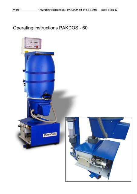
WDT Operating Instructions PAKDOS 60 (V61-04/06) page 1 von 22<br />
Operating instructions PAKDOS - 60
WDT Operating Instructions PAKDOS 60 (V61-04/06) page 2 von 22<br />
Table of Content<br />
page<br />
1. Function 2<br />
2. Technical description 3<br />
2.1 Framework with drum carrier 3<br />
2.2 Powder dosing head 4<br />
2.3 Suspensions- and flushing device 5<br />
2.4 Control board PAK 60 6<br />
2.4.1 Programmes 6<br />
2.4.2 Supervision / external switch off 7<br />
2.5 Demands to the quality of the carbon powder 7<br />
3. Mounting<br />
3.1 Installation into the water circulation<br />
3.1.1 Water take off before the filter 9<br />
3.1.2 Water take off behind the filter - standard 9<br />
3.1.3 Use of town water 9<br />
3.1.4 How to avoid an overflow 9<br />
3.2 Suspensions distribution to several filters 10<br />
3.3 Mounting of the water take off and suspension injection 10<br />
3.4 Electrical installation 10<br />
4. Taking into service 11<br />
4.1 Water flow through the flushing tank 11<br />
4.2 Water level adjustment 11<br />
4.3 Adjustment of the spraying nozzles in the suspension device 11<br />
4.4 Adjustment of the pump pressure switch 11<br />
5. <strong>Operation</strong> 12<br />
5.1 Drum change 12<br />
5.2 Adjustment of the dosing performance – Program switch on „B“ 13<br />
5.3 Back wash– isolation of the PAKDOS 14<br />
5.4 Control of the PAKDOS by a timer / SPS / performance control 14<br />
6. Irritations indication – LED meaning 15<br />
6.1 Short diagnosis 15<br />
6.2 Irritations identification - short 15<br />
6.3 Irritations identification – trouble shooting 16<br />
6.4 Maintenance – taking out of service 18<br />
7. wiring plan - fuses 18<br />
7.1 Connector housing dosing hopper 18<br />
7.2 Connector housing flushing tank 18<br />
7.3 Power plate with external control 19<br />
8. Maintenance protocoll 21<br />
9. Spare parts list 22
WDT Operating Instructions PAKDOS 60 (V61-04/06) page 3 von 22<br />
1. Function<br />
By dosing powdered activated carbon (PAC) onto the filter the concentration of unwanted<br />
and dangerous water ingredients as hydrocarbons and chlorinated hydrocarbons are<br />
reduced to about 10-20%. At diatomite filter this technique is stand of the art (DIN 19643).<br />
The dosing machine PAKDOS 60 meters the PAC by means of a dosing screw directly<br />
from the container into a suspension device, from where the suspension is conveyed to the<br />
filter system by a venturi nozzle. The high dilution of the carbon powder leads to good<br />
mixing into the raw water flow to be treated. The suspension produced in the PAKDOS can<br />
be distributed to up tu 4 filters.<br />
Basis for an effective use of the PAC to improve the water quality is a good functioning filter<br />
as to the DIN 19643.<br />
Attention! The different powder qualities neeed very often different dosing screws for<br />
good function. If there are problems, do not hesitate to contact us.<br />
2. Technical description<br />
the dosing machine PAKDOS 60 consists of:<br />
- Frame with turnable drum carrier<br />
- Suspensions and flushing tank with<br />
Venturi nozzle and booster pump<br />
- Control unit<br />
- Water tapping device<br />
- Pneumatique valves (option)<br />
- Suspensions distribution (option)<br />
measures: space app. 60x70 cm<br />
heigh app. 146 cm<br />
weight app. 50 kg<br />
material: steel, powder coated<br />
other functional parts:<br />
PVC, PE, ABS<br />
seals: Viton, EPDM<br />
container/drum: PE – drum 60 l (Euro)<br />
filling weight 15 – 25 kg<br />
dosing perform: Typ PAK 1200: 10 – 1200 g/h<br />
Typ PAK 2500: 25 – 2500 g/h<br />
Also dependent to the powder quality<br />
Booster pump:<br />
Centrifugal pump 230 V / 0,33 kW<br />
Supply pressure : 0,2 – 2 bar<br />
counterpressure: 0 – 1,8 bar,<br />
dependent on supply pressure<br />
see para 3.1<br />
water flow: 1000 - 1500 l/h<br />
electrique supply:<br />
mains plug 230 V +/- 6%, to be linked to filter pump,<br />
1 drum<br />
2 belts for fasten drum<br />
3 drum ring for fasten dosing hopper<br />
4 dosing unit<br />
5 suspension unit<br />
6 control system<br />
7 locker for drum carrier<br />
8 supporting stand<br />
9 drum carrier
WDT Operating Instructions PAKDOS 60 (V61-04/06) page 4 von 22<br />
2.1 Standsäule mit Fassaufnahme<br />
The rotating drum carrier assembly (9) is fixed to the main vertical support (8). The drum (1) with<br />
PAC is fixed on the carrier assembly (6) by 2 band clamps (2). The dosing hopper (4) is fixed on<br />
the drum in place of the drum lid by use of the spanning ring (3) of the drum. The carrier with the<br />
drum is then turned through 180° to the dosing position, the chemical is dosed into the suspension<br />
system (5) where it is fully suspended and conveyed by a venturi to the filter tubing.<br />
2.2 Dosing head<br />
1 dosing motor 11 drum seal<br />
2 motor holder 12 wore plate for powder activation<br />
3 moving screw for powder activation<br />
4 connector for dosing tube heater 13 flat spring for powder activation<br />
5 dosing screw 14 fitting plate for powder activation<br />
6 guide tube for dosing screw 15 solenoid knocker (not shown)<br />
7 seal tube 16 empty switch (not shown)<br />
8 dosing tube heated 17 connector housing<br />
9 cover for dosing hopper 18 cover for dosing motor<br />
10 dosing hopper<br />
The dosing head ist mounted onto the drum instead of the drum lid and fixed by using the<br />
original spanning ring for the lid. An capacitive switch indicates “drum empty” through the<br />
wall of the dosing hopper.<br />
The powder is activated by a knocker that give every some seconds a stroke to the hopper<br />
wall. To avoid condensation in the dosing tube (8) this is heated.
WDT Operating Instructions PAKDOS 60 (V61-04/06) page 5 von 22<br />
The dosing performance is adjusted to the needs of the water treatment by adjusting dosng<br />
cycles: At every start of a dosing cycle adjustable by the front switch S3 the dosing screw<br />
runs for a certain time, to be adjusted by the front switch S4. The dosing performance is<br />
very dependent on the quality of the powder. So the adjustment according to the table on<br />
page 13 is only a thumb value. But at the end we have to adjust the dosing performance<br />
according to the readings of the water quality. If the water quality is not good enough we<br />
have to dose more, is it better than wanted, we can reduce the dosing.<br />
2.3 Suspension system<br />
For the function of the PAKDOS the pressure conditions are important. The limits are<br />
described under para „Mounting, page 7.<br />
At the standard type the suspension water comes from the circulation water behing the<br />
filter. (supply pressure min. 0,2 bar). Behind the booster pump (26) the high pressure water<br />
is distributed at the distribution part (27) via the floating valve (21) to the suspension tube<br />
(28 - through the rain nozzles 28a) and flushing water through a side nozzle at the floating<br />
valve and booster water to the venturi nozzle (25).<br />
21b<br />
22<br />
20<br />
23<br />
27<br />
26a 26b<br />
22a 21 28a 28 28a<br />
21a 29<br />
26<br />
25<br />
20 pressure switch 26b pump connector pressure side 1"<br />
21 floating valve 27 pressure water distribution PAK<br />
21a floater of floating valve 28 suspensor<br />
22 flushing tank 28a rain nozzles (2 pieces)<br />
22a overflow 29 level switch<br />
23 filter 300 for flushing water 30 pressure washers (in union)<br />
24 flow switch 31 transparant detection tube -<br />
25 venturi nozzle with Opto-sensor (option)<br />
26 boster pump 31a gauge connector ¼“<br />
26a pump connector suction side 32 isolation valve d25<br />
1 ¼“ with gauge connector<br />
The produced PAC-suspension is sucked off by the venturi (25) from the suspension tube.<br />
The black powder is to be seen shortly after dosing in the transparent suction tube (with the<br />
24<br />
32<br />
31<br />
31a<br />
30
WDT Operating Instructions PAKDOS 60 (V61-04/06) page 6 von 22<br />
flow switch 24) and the transparent detection tube with the optional available opto-sensor to<br />
monitor the dosing function. The suction power of the venturi is adjusted at taking into<br />
service by fitting a washer into the union behing the venturi nozzle: is the suction power too<br />
high, use a nozzle with smaller hole, ist the suction power too low, use one with bigger hole.<br />
A set of these washers is packed by to the machine. The pressure and flow situation is<br />
monitored by the pressure switch (20) on top of the booster pump, level switch (29) in the<br />
flushing tank and the flow switch (24) below the venturi. Dosing and also the booster pump<br />
are switched off in case of any irritations situation. The irritation is indicated by the 4 red<br />
LEDs at the front plate. The switch bobbin of the flow switch (24) functions as a non return<br />
valve to avoid a high rate backflow of suspension from the flushing tank in case of switch<br />
off. To avoid completely a backflow at switch off, e.g. at back wash of the filter, pneumatic<br />
isolation valves may be installed in the supply and dosing tube.<br />
Switching the PAKDOS through a timer watch and using the program BZ the tubing of the<br />
PAKDOS is rinsed for 1 minute without dosing to clean the tubing.<br />
2.4 Control system<br />
The microprocessor based control system fitts three functions:<br />
- Dosing and test programmes with 3 switches<br />
- Functions and irritations identification by means of 1 green and 4 red LEDs<br />
If an irritation occurs, the dosing is switched off automatically<br />
- Short diagnosis and function check<br />
2.4.1 Programmes<br />
4 test programmes to check the set dosing performance:<br />
B 5: dosing 5 minutes<br />
B10: dosing 10 minutes<br />
B15: dosing 15 minutes<br />
B30: dosing 30 minutes<br />
After the end of the test the green LED is blinking
WDT Operating Instructions PAKDOS 60 (V61-04/06) page 7 von 22<br />
K: knocker 1 minute all 4 seconds – no dosing<br />
P: - only for authorised personal.<br />
2 service programs:<br />
B: normal service program with continuous dosing<br />
BZ: service based on timer watch. Dosing is active, when the control input on conn.<br />
S04,7-8 is closed. If the input is opened dosing is stopped, the booster pump is<br />
running on for another minute to flush the dosing tubing. The green LED is blinking.<br />
This program may be used for an external dosing control e.g. if a measuring system<br />
for the combined chlorine is used. Within a cycle time of 1 minute dosing may be<br />
activated from 1-60 seconds. See para 5.4<br />
If changing a program dosing Stopps and the green LED blinks for 4 seconds.<br />
2.4.2 Monitoring / external switch off<br />
All functions are monitored. In the case of an irritation, dosing is switched off, the<br />
irritation is indicated and identified by means of the LED. Dosing is indicated by flickering of<br />
the LED 4. Remote fault control non volt is available – see wiring diagram para 6.<br />
For daily switch off it is recommended to use the program BZ for timer control.<br />
2.5 Needed specification of the carbon powder<br />
there are a lot of different qualities of PAC on the market. They differ in the physical<br />
properties as in the selectivity on the water chemicals. For a wanted effect on the water<br />
quality with different PAC may be needed different dosing rates. So it may be necessary to<br />
alter the dosing rates / the set values at the front plate even from 1 drum to another.<br />
A high content of fine dust ore humidity may lead to blocking of the screw. Coarse grains<br />
may block the suspension tube or the venturi nozzle.<br />
Attention! Some qualities need special dosing screws. Please contact us if problems<br />
with the dosing occurs.<br />
3 Mounting<br />
3.1 Installation of the PAKDOS into the water circulation<br />
for mounting and operation a place of app. 1x1,5m is needed.<br />
For a good function the pressure conditions are important. So we use 2 booster pumps<br />
for different pressure levels. For a low pressure level, e.g. preferred dosing before the<br />
circulation pump, we use the pump HMS3 which may cover following pressure levels:<br />
At supply pressure 1,2 bar possible counter pressure 1,4 bar<br />
0,6 bar 1,1 bar<br />
0,3 bar 0,9 bar<br />
for higher counter pressures we use the pump HMS4 with which pressures may be covered
WDT Operating Instructions PAKDOS 60 (V61-04/06) page 8 von 22<br />
At supply pressure 1,2 bar possible counter pressure 2,0 bar<br />
0,6 bar 1,8 bar<br />
0,3 bar 1,5 bar<br />
To measure the existing pressures before and behind the booster pump there are hose<br />
unions 6x1 to connect the water gauge supplied with the machine.<br />
Attention! If the measuring water is taken from before filter and behind injection<br />
point of the PAC you’ll get wrong – far too low - readings of free chlorine. The<br />
measuring water take off must be before the injection point of the PAC!<br />
3.1.1 Water take off between circulation pump and filter<br />
respectively to the pressure conditions see before<br />
1. water take off directly behind the filter pump before the non return valve<br />
2. dosing behind the non return valve before injection of the flocculant but behind take off<br />
of the probe water<br />
3. pay attention to low pressure loss:<br />
- short distances<br />
- hose 1“ or tubing d25, for longer distances use bends instead elbows<br />
- only use the by-packed isolation valves<br />
4. for the connections female threads 1“ are needed with no enclosers. The diameter of<br />
the water take off tube is 26mm.
WDT Operating Instructions PAKDOS 60 (V61-04/06) page 9 von 22<br />
3.1.2 Water take off from behind filter:<br />
In an outdoor pool it may be advantageous to take the water from behind filter as this water<br />
is cleaned by the filter. Here is only to be seen for the pressure situation. The booster pump<br />
of the PAKDOS needs a positive pressure of at least 0,2 bar. Dosing point principaly before<br />
the circulation pump.<br />
3.1.3 Use of town water<br />
Town water is used best<br />
- at diatomite filters where only few fresh water is needed for the back wash of the filter<br />
and fresh water is added anyhow.<br />
- if the supply of several filters with the PAC suspension from one filter circulation makes<br />
problems<br />
Supply pressure min 3 bar. - mount a pressure control device<br />
Pay attention to the regulation to protect the town water.<br />
3.1.4 How to avoid an overflow<br />
At switch off of the PAKDOS 60, especially at irritations of the filter system or only at<br />
automatic filter back wash, the open flushing system of the PAKDOS remains connected to<br />
the water circulation. As the standard isolation devices to the flushing tank, as floating<br />
valve and flow switch bobbin are not able to isolate 100% (especially when the<br />
maintenance is not made correctly), we get a slight overflow of black water.<br />
A 100% isolation is only possible by installing membrane valves to the inlet and outlet of<br />
the machine which are closed automatically if an irritation leads to a stop of the machine.<br />
3.2 Suspensions distribution on several filter circulations (PAK SV)<br />
The suspension produced by the PAKDOS 60 of app. 1000 l/h can be distributed to several<br />
different filter circulations by dosing lines. The device consists of an isolation ball valve d25,<br />
a flow meter 100-1000 l/h as a ball valve d20V to adjust the flow to the filter. For automatic<br />
function we use pneumatic membrane valves which isolate all dosing lines at an irritation<br />
event at one filter. A short interruption of the PAC dosing does not affect the general<br />
cleaning effect of the PAC.<br />
Water take off from behind the filter, dosing point before the circulation pump.<br />
Never mount additional isolation valves to the system!<br />
3.3 Mounting of the water take off and suspension injection device<br />
Attention! The ellbow injection tubes<br />
have a diameter of 26 mm. The female<br />
threads must be free!<br />
Cut the injection tube as shown and glue<br />
it into the ball valve connection.<br />
- Mark the opening side of the elbow<br />
tube at the adapter.<br />
- after hardening ( app. 1 hour ) screw in<br />
the injection device as shown in the<br />
picture. To tighten the connection only<br />
seize the adapter! Otherwise you could<br />
loosen the glue.
WDT Operating Instructions PAKDOS 60 (V61-04/06) page 10 von 22<br />
3.4 Connection of the control cables to a central control board<br />
For the fault remote and to control the machine you need for both a non volt contact to be<br />
connected on the control plate of the PAKDOS - see para 7.<br />
Principally use only flexible cables max. 0,5 2<br />
4. Taking into service / adjustment of the flushing system (see diagram page 5)<br />
Dosing is switched off at the front plate, the valves at the tapping points are open.<br />
The valves at the PAKDOS are closed.<br />
Now open the inlet ball valve top of the filter. Water flows into the tank. When the tank is<br />
half full, open the outlet ball valve at the machine and switch on the machine.<br />
If town water is used the machine can be switched on immediately after opening all valves.<br />
4.1 Water flow<br />
A good water flow through the flushing tank is the basis of a good function of the PAKDOS..<br />
this flow relates to the suction power of the venturi. By means of the washer (30) this<br />
suction performance is adjusted to the pressure conditions. If the water level in the tank<br />
falls steadily, the suction power is too big, you must fit a washer with a smaller bore. If the<br />
level rises, you need a washer with bigger bore or use without washer. The switch bobbin of<br />
the flow switch must be pressed up in the flow switch holder (24), the LED at the switch<br />
must not burn.<br />
Off works a washer with a 6mm bore is fitted, washers with bores 5,5 and 7mm are in the<br />
spare parts kit in the by-pack. If there is no good flow possible, meter the supply and<br />
counter pressure and compare with the table para 3, page 6. for this a water gauge is<br />
packed by which is to be connected to the adapters 26a und 31a.<br />
Attention! At the mounting works different particles may be fallen into the flushing<br />
tank as cut parts from cable or pvc. Durch mehrmaliges Abdrücken des<br />
Saugschlauches oder Schließen des Ablaufhahnes die Beweglichkeit des<br />
Schaltkörpers prüfen.<br />
Vibriert das Schwimmerventil am Arbeitspunkt, Schwimmerventil öffnen und den O-<br />
Ring am Ventilkegel abnehmen<br />
4.2 water level in the flushing tank<br />
A higher level you get by crewing out the floater (21a) a lower level by srewing it in. one<br />
turn relates to app. 1 cm. Please adjust the level at the situation of good flow through the<br />
tank to medium between level low and level high.<br />
4.3 Adjustment of the rain nozzles<br />
The suspension water to humidify the powder falling onto the water surface should rain<br />
smoothly from the nozzles (28a). For adjustment you screw in or out the by-pass nozzle at<br />
the outlet of the floating valve: comes the water from the rain nozzles too hard, open the bypass<br />
nozzle and reverse. If the water comes too hard, the fine dropplets may come up to<br />
the dosing nozzle and this could be blocked.<br />
4.4 Adjustment of the pressure switch<br />
The pressure switch, fitted pressure side of the booster pump, is to monitor the<br />
performance of the pump. If the pump runs well, there should be a pressure of at least 1,5<br />
bar. If the pressure falls down, obviously there is something wrong with the pump: maybe<br />
air in the supply tubing, anything broken. Off works the switch is adjusted to 1,5 bar. On
WDT Operating Instructions PAKDOS 60 (V61-04/06) page 11 von 22<br />
operation the switch point can be changed by the adjusting screw from 1-3 bar. If changed,<br />
it must be sure, that at any operating time the supply pressure is minimum 0,2 bar.<br />
5 <strong>Operation</strong><br />
5.1 Drum change<br />
As the powder can be compressed within the drum by vibration on transport and this could<br />
make problems at dosing, please roll the drum on the floor before loading some times.<br />
1. turn up the empty drum and take it off together with the the dosing head<br />
2. open the new drum and take off the lid – let the spanning ring at the drum<br />
3. position the dosing hopper on the open drum so that the cable is coming on right side<br />
and fix it with the spanning ring.<br />
In summer time the drum may be heated and the air in the drum may have a positive<br />
pressure. So carfully open the drum.<br />
Sicherungsblech am Klemmbügel einsetzen und umbiegen.<br />
4. position the new drum on the carrier, so that the handle fits into the slide at the frame.<br />
The drum must stand symmetrically on the drum carrier, touching the rear rails<br />
5. Fix the drum securely in position using the drum band clamps. Adjust the clasp tension<br />
by adjusting the nuts on the screwed end of the band clamps. Lock the clamp clasps<br />
with the securing clips provided so that they cannot open by itself.<br />
6. unlock the drum carrier swivel lock (7) and slowly rotate the drum and carrier left side<br />
through 180°. Care should be taken not to stretch or entangle the cable joining the<br />
hopper to the control box.<br />
Lock the drum carrier in this position via the swivel lock right at the frame<br />
7. Now push the sealing tube (7) over the suspension tube<br />
the PAKDOS in the dosing position
WDT Operating Instructions PAKDOS 60 (V61-04/06) page 12 von 22<br />
5.2 Adjustment of the dosing performance – Program switch on “B” or “BZ”<br />
Diagram for the determination of the switch positions for the cycle and dosing time<br />
100% dosing performance are at the PAKDOS 60/1200 app. 1200 g/h.<br />
Cycle Schalterstellung Time<br />
Dosing<br />
Schalterstellung<br />
Dosing time<br />
% für switch Zykluszeit pos.<br />
Performance Dosierleistung % für Dosierzeit switch pos.<br />
%<br />
% Schalter S3 % % Schalter S4<br />
100<br />
90<br />
80<br />
70<br />
60<br />
50<br />
40<br />
30<br />
20<br />
10<br />
9<br />
8<br />
7<br />
6<br />
16<br />
14<br />
12<br />
10<br />
Table for cycle and dosing times<br />
8<br />
6<br />
4<br />
2<br />
1<br />
100<br />
80<br />
60<br />
40<br />
20<br />
10<br />
5<br />
1<br />
0,5<br />
PAKDOS 1200<br />
PAKDOS 4000<br />
Schalter-<br />
Switch pos.<br />
stellung<br />
Cycle time Zykluszeit seconds<br />
Dosierzeit<br />
dosing time seconds<br />
Schalter S4<br />
Sek. % Sek. %<br />
1 493 6 4 13<br />
2 411 8 5 16<br />
3 342 9 6 19<br />
4 285 11 7 22<br />
5 238 13 8 25<br />
6 198 16 9 28<br />
7 165 19 10 31<br />
8 138 23 11 34<br />
9 115 28 13 41<br />
10 95 34 15 47<br />
11 80 40 17 53<br />
12 66 48 19 59<br />
13 55 58 22 69<br />
14 46 69 25 78<br />
15 38 84 28 88<br />
16 32 100 32 100<br />
100<br />
90<br />
80<br />
70<br />
60<br />
50<br />
40<br />
30<br />
20<br />
10 9<br />
8<br />
7<br />
6<br />
16<br />
14<br />
12<br />
10<br />
8<br />
6<br />
4<br />
2
WDT Operating Instructions PAKDOS 60 (V61-04/06) page 13 von 22<br />
Example:<br />
The need of PAC is, depending on water quality actual and wanted, at app. 0.5-2 g/m³/h<br />
circulated water. For the first we work with a dosing rate of 1 g/m³/h. At a filter circulation of<br />
300 m³/h we would need a dosing performance of 300 g/h. These are 25% of the dosing<br />
capacity of 1200 g/h having the PAKDOS 60/1200.<br />
At the diagram you lay a straight line through 25% on the middle line meating a switch<br />
position on the cycle time line, here 12. on the dosing time line the line meats the switch<br />
position 11. All 66 seconds the dosing motor will work for 17 seconds as shown in the table<br />
below the diagram. This setting is only for first approximation.<br />
By measuring the water quality after 2-3 days you will find whether the dosing was<br />
right, too high or too small. So you adjust the dosing rate by means of the dosing<br />
time switch as needed to your water quality.<br />
5.3 Back wash – isolation of the PAKDOS<br />
At back wash the PAKDOS must be isolated from the filter to avoid a PAC-dosing to the<br />
filter. If a suspension distribution is installed this is automatically done as the control valves<br />
are closed for this time.<br />
Doing the back wash <strong>manual</strong>ly you must switch off the PAKDOS and close the ball valves<br />
at the PAKDOS.<br />
5.4 Control of the PAKDOS by a switch timer / SPS / performance control<br />
Switch timer: Program switch on „BZ“. Position the lever at the watch to the „watch“ sign.<br />
For the wanted dosing time the timer levers must be pushed outside, At the end of the set<br />
time dosing stops and the pump runs on for a further minute to flush the machine and the<br />
tubing. In the switch off time the green LED flickers.<br />
SPS: Program switch on „BZ“. To activate the PAKDOS the control contact (S04,7-8) is to<br />
be closed. At the end of the set time dosing stops and the pump runs on for a further minute<br />
to flush the machine and the tubing. In the switch off time the green LED flickers.<br />
Performance control: Program switch on „BZ“. The switch for dosing cycle and dosing<br />
time are to be set on 16. by pulsing the control contact (S04,7-8) within 1 minute every<br />
wanted dosing performance from 0-100% can be set. If the control contact remains longer<br />
than 1 minute open, the machine stops, the green LED flickers. By closing the contact<br />
again the machine starts again.<br />
6. Irritation identification / trouble shooting<br />
6.1 Short – diagnose<br />
When the machine is switched on a diagnosis programme for the control equipment runs.<br />
The same happens when the reset key is pressed.<br />
1. All lights burn together 3 seconds<br />
2. Each light comes on one after another for one second<br />
3. If there is no fault, all red lamps go out and the dosing programme commences.
WDT Operating Instructions PAKDOS 60 (V61-04/06) page 14 von 22<br />
6.2 LED Indicators for function and irritations<br />
Grüne LED L0:<br />
Green LED – indicates program switch and external inputs<br />
on contiuously: GRANUDOS in operation<br />
no light: Transformer Tr. 2 or fuse F1 for control system burnt<br />
fast blink (0,5 second on, 0,5 second off...)<br />
- programme knob not on a programme position<br />
- end of test programme<br />
- dosing switched off with front fascia switch<br />
slow blink (2 seconds on, 2 seconds off)<br />
External switch off e.g. by a central control on conn. S04-5<br />
Flickering:<br />
- dosing switched off on program BZ<br />
- external switch off of dosing on connector S04-4<br />
-<br />
Red LED shows function of dosing and interruptions indicated by the different<br />
Sensors. At any interruption dosing stops. Flickering of L4 shows that the dosing motor is<br />
activated, the motor should run.<br />
LED irritation what<br />
happens<br />
see below<br />
L1 burns water level high 2<br />
water flow too low<br />
L2 burns water level low 1<br />
pump pressure low 1<br />
L3 burns counter pressure high (external) 1<br />
L4 burns dosing hopper empty 3<br />
blink slow fuse F2 315 mAT – dosing motor 2<br />
L1 + L4 L1 blink slow fuse F3 800 mAT or power transformer faulty 1<br />
L4 blink fast<br />
Effect 1: dosing stops, booster pump stops<br />
Effect 2: dosing stops<br />
Effect 3: only indication, no further
WDT Operating Instructions PAKDOS 60 (V61-04/06) page 15 von 22<br />
6.3 Fault identification - trouble shooting<br />
Attention – an indicated irritation may result by a fauly switch too! Switches out of<br />
function if disconnected. Fault indication must go, if the switch is disconnected!<br />
irritation reason / trouble shouting<br />
L1 burns: It comes more water to the flushing tank as is sucked off<br />
Level high, If there is a good suction down in the flushing cone:<br />
Flow low<br />
dosing stops<br />
1. Floating valve hangs or diaphragm faulty –<br />
2. Suspensor blocked by coarse particles. I<br />
If there is no good suction: flow switch bobbin down, switch LED<br />
burns<br />
3. booster pump blocked by big parts – dismantle and clean<br />
4. prefilter blocked – clean it<br />
5. particles in the venturi - dismount<br />
6. higher counter pressure – use bigger washer or take it out<br />
7. flushing cone blocked – clean it<br />
L1+L4 blink slow fuse F3 of the power supply or transformer Tr.1 24 VDC faulty<br />
L2 burns: it comes less water to the flushing tank as is sucked off by the<br />
venturi,.<br />
Level low,<br />
machine stops 1. prefilter blocked – clean it<br />
2. floating valve blocked – clean it or new diaphragm<br />
3. low counter pressure – fit smaller washer –(see. Para 4.1)<br />
L2 burns pump pressure too low<br />
pump pressure low 1. prefilter blocked – clean it<br />
2. air in the pump – carefully deaerate<br />
machine stops<br />
3. pressure switch not right adjusted – if readjusting not<br />
possible, disconnect (s. Punkt 4.4)<br />
L3 burns: if pressure switch is fitted in the water circulation tubing to monitor<br />
the right filter / back wash / automatic valve function:<br />
machine stops something is wrong depending on switch function<br />
Attention! This irritation can only be put out by a “reset”<br />
L 4 burns 1. drum empty<br />
drum empty<br />
No further reaction If drum not empty: falls<br />
2. empty switch to be new adjusted:<br />
turn drum to top, take off the motor cover (18). Right side at the<br />
hopper you see the square empty switch. By means of the small<br />
screw driver you turn to right, till the switch LED burns then left till<br />
LED is out, plus about 10°
WDT Operating Instructions PAKDOS 60 (V61-04/06) page 16 von 22<br />
3. Empty switch is faulty – fit a new one<br />
L4 blink slow fuse F2 of the dosing motor 315 mAT burnt<br />
1. dosing motor may be blocked by<br />
- particles in the powder<br />
- blocking of the powder in the dosing screw<br />
- blocking of the dosing tube maybe by<br />
humidity<br />
In every case dismount the dosing motor with the screwThe screw<br />
must have a very smooth surface. Clean dosing tube proper.<br />
2. dosing motor faulty<br />
L4 blinks fast Option: if opical sensor is fitted to monitor the powder dosing:<br />
For longer than 8 minutes no powder has been seen by the sensor.<br />
1. reasons for that as above indicated<br />
adjustment of the with clear water and clean transparent tube the switch LED must<br />
opto sensor burn. Turn adjusting screw to left till end (LED off) then again to right<br />
(Carlo Gavazzi) till the LED burns + 10°<br />
.
WDT Operating Instructions PAKDOS 60 (V61-04/06) page 17 von 22<br />
6.4 Maintenance / taking out of service<br />
1. use only good powder qualities – see para 2.5<br />
2. hold prefilter proper<br />
3. check the function of the rain nozzles more often, continuous, smooth rain<br />
4. check the function of the monitoring switches<br />
5. with every new drum or at least all 2 months clean the suspension tube and tank<br />
properly by means of by-packed brush<br />
6. at same time clean the heated dosing tube til the upper elbow by means of the small<br />
round brush<br />
7. every year change the diaphragm of the floating valve and the seal ring of the flow<br />
switch bobbin<br />
8. hold clean the transparent tube of the opto-sensor<br />
for longer time of take out of service turn up the hopper, take out the dosing motor with the<br />
screw clean the screw properly from all particles. Refit the screw only at next taking into<br />
service.<br />
The maintenance jobs are listed in the attached list.<br />
7 Wiring at the dosing hopper and the flushing tank<br />
7.1 Dosing hopper<br />
Blue<br />
Rose<br />
Grey<br />
The knocker is connected directly<br />
7.2 Wiring at the flushing tank<br />
Yellow<br />
Green<br />
White<br />
brown<br />
Connector no. on the power plate<br />
Yellow<br />
green<br />
white<br />
brown<br />
grey<br />
7.3 Leistungsplatine / Netzkarte<br />
Connector no. on the power plate<br />
Blue<br />
brown<br />
black<br />
white<br />
brown<br />
White<br />
brown<br />
Empty switch<br />
Heating<br />
dosing nozzle<br />
- dos. motor<br />
+ 24VDC<br />
level min<br />
switch max<br />
flow switch<br />
pressure<br />
switch<br />
dosing<br />
monitoring<br />
(option)
WDT Operating Instructions PAKDOS 60 (V61-04/06) page 18 von 22<br />
7.3 Wiring at the power plate, fuses, transformers<br />
S 010<br />
1<br />
2 3 4 5 6<br />
S 011<br />
Tr. 1<br />
1<br />
2 3 4 5 6<br />
Rel. 2<br />
F1 fuse for supply 230 VAC incl. knocker 1,25 Atr<br />
F2 fuse dosing motor 315 mAtr<br />
F3 fuse all power outputs 24 VDC 800 mAtr<br />
F4 fuse supply 6 VDC processor plate 315 mAtr<br />
F0 mains fuse at front plate 6,3 Atr<br />
Tr1 power transformer 16 VA, 18 Volt<br />
Tr2 controller transformer 1,5 VA, 6 Volt<br />
Rel.1 booster pump, solenoid valve<br />
Rel.2 knocker<br />
Rel.3 fault remote<br />
S 012<br />
1<br />
2 3 4 5 6<br />
S 013<br />
Tr. 2<br />
S 01<br />
Push conn.<br />
coding<br />
Flat cable<br />
S 02<br />
1 2 3 4 5 6 7 8 9 10<br />
S 03<br />
1 2 3 4 5 6 7 8 9 10<br />
S 04<br />
1 2 3 4 5 6 7 8 9 10
WDT Operating Instructions PAKDOS 60 (V61-04/06) page 19 von 22<br />
connectors for 230 VAC 6 x 5 mm<br />
push connector S010 push connector S011<br />
1+2 230 V booster pump 1+2 230 V reserve<br />
3 PE 3 PE<br />
4+5 230 V control valve 4+5 230 V reserve (booster pump)<br />
6 PE 6 PE<br />
push connector S012 push connector S013 (4x5mm)<br />
1+2 230 Volt mains 1+2 mains 230 Volt timer watch<br />
3 PE mains 230 volt 3 PE<br />
4 +205 VDC knocker (black1)<br />
5 - 205 VDC knocker(black 2)<br />
6 PE Klopfer<br />
push connector 8 x 3,5 mm low voltage / non volt<br />
push connector S01 push connector S02<br />
fault remote non volt/ max 24V/ 8A control cable from the dosing head<br />
1 normally open 1 empty switch (inductive)<br />
2 C-contact 2 - 24 VDC empty switch<br />
3 normally closed 3 +24 VDC empty switch<br />
4-6 reserve 4-6 reserve<br />
7 - 24 VDC dosing motor<br />
8 +24 VDC dosing motor<br />
9 - 24 VDC heating dos. nozzle<br />
10 +24 VDC heating dos. nozzle<br />
push connector S03 push connector S04<br />
control cable from the flushing tank external controls<br />
switches normally open, function to be<br />
bridged to mass<br />
1 reserve<br />
2 - mass 1 counter pressure (ext.) max<br />
3 water level in tank max, or flow low 2 pump pressure min<br />
4 dosing monitoring (option) 3 - mass<br />
5 - mass 4 dosing off<br />
6 + 24 VDC 5 PAKDOS off<br />
7,8 reserve 6 - mass<br />
9 water level in tank, pump pressure min. 7-8 switch timer for program BZ<br />
10 - mass (operation if switch is closed)<br />
for the control cbles to the connector housing please only use flexible ones max 0,5²
WDT Operating Instructions PAKDOS 60 (V61-04/06) page 20 von 22<br />
8. Maintenance protocol PAKDOS 60<br />
Objekt:......................................................................................................................................<br />
PAKDOS type:...............................................................year:........................................<br />
Maintenance executed on:............................................by:................................................<br />
Subscription by the operator:....................................................................................<br />
↓↓ This must be done!<br />
1 Suspensions and flushing<br />
1.1 check level switch: OK [ ] change switch [ ]<br />
1.2 check pressure switch: OK [ ] change switch [ ]<br />
1.3 check flow switch: OK [ ] change switch [ ]<br />
1.4 change flow switch diaphragm [ ] change bobbin [ ]<br />
1.5 change floating valve diaphragm and O-ring [ ]<br />
1.6 check floating valve function OK [ ] adjust water level [ ]<br />
1.7 clean suspensor and flushing tank [ ]<br />
1.8 clean rain nozzles [ ]<br />
1.9 check slide ring seal [ ] change [ ]<br />
1.11 clean pre-filter d75 and fine filter 300 [ ]<br />
2 dosing head<br />
2.1 function heating: OK [ ] change heated nozzle [ ]<br />
2.2 function empty switch: OK [ ] change switch [ ]<br />
2.3 current dosing motor: I max: 150+/- 30 mA OK [ ] change motor [ ]<br />
2.4 change seal of dosing motor [ ]<br />
2.5 check and clean dosing screw OK [ ] change [ ]<br />
2.6 check flat spring with wore plate OK [ ] change [ ]<br />
2.7 check knocker function OK [ ] change [ ]<br />
3 additional jobs
WDT Operating Instructions PAKDOS 60 (V61-04/06) page 21 von 22<br />
9. spare parts list PAKDOS 60<br />
the positions nos. relate to the sketches on the indicated pages<br />
1. dosing head page 4<br />
Pos. designation article code no.<br />
1 dosing motor PLG 30 - 60 11546<br />
3 moving srew PAK 24x16x85 11779<br />
5 dosing screw PAK d16,5 x140 with kit 11773<br />
7 sealing tube 125/70 on suspensor PAK 11783<br />
8 dosing nozzle PAK heated d25x100 PTFE 11780<br />
9 cover dosing hopper PAK 11760<br />
10 dosing hopper PAK 60 without techniques 11759<br />
11 seal 8x8 EPDM for dosing hopper, length 1,2m 11534<br />
12 wear plate PTFE for blade spring 11771<br />
15 knocker PAK complete 11764<br />
16 empty switch 10337<br />
18 motor protection cover PAK 14046<br />
2. suspensions and flushing system page 4<br />
(19) filter d75 GPL/PAK complete 11804<br />
filter insert d75 GR/PAK SS 11640<br />
O-ring filter top d75 EPDM 11258<br />
20 pressure switch M10x1, 1-3 bar 17275<br />
21 floating valve d25 PAK complete 11798<br />
diaphragm kit for floating valve d25 GR/PAK 11619<br />
21a floater 11621<br />
21b elbow 3/8"-6x1 to floating valve 11616<br />
23 filter 1/2" 300u flushing water PAK 11797<br />
filter element 300µm SS 10482<br />
24 water flow monitoring with<br />
24a flow switch holder 1/2" -S14 -US 12729<br />
24b flow switch 18x1 ind. for GR/PAK, lead 0,6m 11603<br />
24c flow switch bobbin 1/2" US 12730<br />
25 venturi PAK 3/8" complete 11591<br />
26 booster pump Lo 2HMS4 10658<br />
booster pump Lo 2HMS3 18181<br />
26c slide ring seal Lo 2HMS 3/4-A 12800<br />
27 fitting booster pump Lo3/4 to venturi w/o filter 19813<br />
28 suspensor PAK (PE-tank) 11801<br />
28a rain nozzle PAK complete 11803<br />
29 level switch flushing tank 3/8" GR/PAK 10496<br />
30 orifice washers kit 5,5 - 6 - 7 mm 11594<br />
31 photoelectric switch, diffuse refl (option) 10342<br />
3. controlling page 6<br />
cover control housing 12600<br />
locker Plexi for controller housing Vario Box 11967<br />
mains switch GR/PAK 11338
WDT Operating Instructions PAKDOS 60 (V61-04/06) page 22 von 22<br />
mains fuse holder on front plate GR/PAK 12324<br />
turn key knob 4mm for control board MCU 11757<br />
5. control power plate page18<br />
transformer board NTPAK-A flat cable 11755<br />
transformer power supply 240/18 volt -888 mA 11665<br />
transformer 240/6 volt 250 mA, 1,5 VA 10929<br />
6. control plate<br />
control board MCU 1c exchange part 12225<br />
fuses - set for GR 10-100 / PAK 11752