Gestra Products Technical - Control And Power
Gestra Products Technical - Control And Power
Gestra Products Technical - Control And Power

Create successful ePaper yourself
Turn your PDF publications into a flip-book with our unique Google optimized e-Paper software.
mA V<br />
Basics<br />
MIN (NW) (LW)<br />
Self-monitoring<br />
conductivity<br />
level electrodes<br />
NRG 1...-40<br />
24 V DC<br />
↔ bus signal (2x)<br />
Visual display unit Level switch<br />
NRS 1-40 / NRS 1-40.1<br />
with automatic testing<br />
routine (in control<br />
cabinet)<br />
(1x)<br />
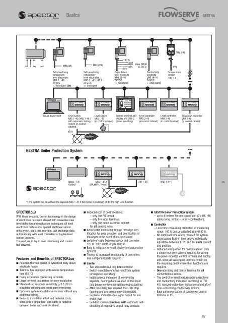
GESTRA Boiler Protection System<br />
Wago – I/O<br />
<strong>Control</strong><br />
SPECTORbus<br />
With these systems, proven technology in the design<br />
of electrodes has been alloyed with innovative new<br />
level detection and evaluation techniques: All level<br />
electrodes feature now special electronic sensor<br />
units which, via a bus interface, can exchange data<br />
automatically with level controllers or higher-level<br />
control systems.<br />
The next era in liquid level monitoring and control<br />
has dawned.<br />
Features and Benefits of SPECTORbus<br />
n Patented thermal barrier in cylindrical body above<br />
electrode flange<br />
n Terminal box equipped with excess temperature<br />
fuse (85 °C)<br />
n Freely accessible connecting terminals<br />
n Large terminal box makes for easy installation<br />
n Standardized response sensitivity ≥ 0.5 µS/cm<br />
simplifies stocking and spare part inventories<br />
n Optimum system adaptation/extension without any<br />
additional wiring<br />
n Reduced installation effort and material costs,<br />
since only a single four-core cable is required<br />
between boiler and control cabinet<br />
MAX (HW)<br />
Self-monitoring<br />
conductivity<br />
level electrodes<br />
NRG 1...-41/.-41.1<br />
24 V DC<br />
↔ bus signal<br />
Level switch<br />
NRS 1-41<br />
(in control cabinet)<br />
NRS 1-40.1<br />
(LW, HW*), Temp.)<br />
100 %<br />
MAX<br />
MIN<br />
0 %<br />
Capacitance<br />
level electrode<br />
NRG 26-40<br />
24 V DC<br />
↔ bus signal<br />
<strong>Control</strong> terminal and<br />
display unit URB 2<br />
(panel mounting)<br />
*) The system can do without the separate NRS 1-41 if the burner is switched off by the high level function<br />
Valve OPEN/<br />
CLOSED<br />
n Reduced cost of control cabinet<br />
– only one PG thread<br />
– only five input terminals<br />
– only one cable in control cabinet<br />
for all sensing units<br />
n Active cable monitoring through message identification<br />
for error detection and prioritisation of<br />
messages in the event of low-level alarm<br />
n Length of cable between sensor and controller<br />
125 m; max. cable length 1000 m<br />
n Easy to integrate in visual display and automation<br />
systems<br />
n Thanks to increased functionality of controllers<br />
less component parts required<br />
n Limiter<br />
– Two electrodes but only one controller<br />
– Switch-selectable one/two-electrode system<br />
(emergency operation)<br />
– Instantaneous indication of low level by<br />
separate, flashing diode as soon as the liquid<br />
falls below low level (simplifies routine testing)<br />
– After time delay has elapsed, the LEDs stop<br />
flashing and are permanently illuminated<br />
– Separate, instantaneous signal output for low<br />
water level<br />
– Self-test routine combined with automatic selfchecking<br />
of respective output relay contacts<br />
Conductivity<br />
electrode<br />
LRG 16-40<br />
24 V DC<br />
↔ bus signal<br />
Level controller<br />
NRS 2-40<br />
(in control cabinet)<br />
STB<br />
Temperature<br />
sensor<br />
TRG 5-6...<br />
Level controller<br />
NRR 2-40<br />
(in control cabinet)<br />
LRR 1-40 NRS 1-41*)<br />
TRV 5-40<br />
Blowdown controller<br />
LRR 1-40<br />
(in control cabinet)<br />
n GESTRA Boiler Protection System<br />
– up to 4 limiters for one control unit (2 x LW, HW,<br />
safety temp. limiter – in any combination).<br />
n <strong>Control</strong>ler<br />
– Less time-consuming calibration of measuring<br />
range; 100 % can be adjusted at level 50 %.<br />
– No additional time relays required for system<br />
optimization. Built-in time delays individually<br />
adjustable between 1...25 sec. for each contact<br />
and position.<br />
– Reduced wiring effort for control cabinet: Only<br />
a single four-core cable is required for wiring<br />
the panel-mounted control terminal and display<br />
unit, since all switchgear controls remain on<br />
the mounting panel where their functions are<br />
required.<br />
– One operating and control terminal for all<br />
connected bus nodes.<br />
– The control terminal features permanent level<br />
and conductivity indication according to TRD<br />
401 (second water-level indication) and draft of<br />
rules concerning conductivity limiters.<br />
– Easy parameterization of controls on control<br />
terminal or PC.<br />
87<br />
B