SFA-5.16
SFA-5.16
SFA-5.16

Create successful ePaper yourself
Turn your PDF publications into a flip-book with our unique Google optimized e-Paper software.
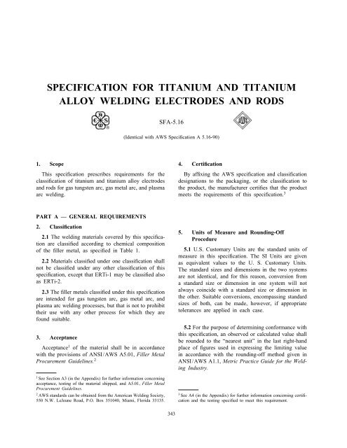
SPECIFICATION FOR TITANIUM AND TITANIUM<br />
ALLOY WELDING ELECTRODES AND RODS<br />
1. Scope<br />
This specification prescribes requirements for the<br />
classification of titanium and titanium alloy electrodes<br />
and rods for gas tungsten arc, gas metal arc, and plasma<br />
arc welding.<br />
PART A — GENERAL REQUIREMENTS<br />
2. Classification<br />
2.1 The welding materials covered by this specification<br />
are classified according to chemical composition<br />
of the filler metal, as specified in Table 1.<br />
2.2 Materials classified under one classification shall<br />
not be classified under any other classification of this<br />
specification, except that ERTi-1 may be classified also<br />
as ERTi-2.<br />
2.3 The filler metals classified under this specification<br />
are intended for gas tungsten arc, gas metal arc, and<br />
plasma arc welding processes, but that is not to prohibit<br />
their use with any other process for which they are<br />
found suitable.<br />
3. Acceptance<br />
Acceptance1 of the material shall be in accordance<br />
with the provisions of ANSI/AWS A5.01, Filler Metal<br />
Procurement Guidelines. 2<br />
1 See Section A3 (in the Appendix) for further information concerning<br />
acceptance, testing of the material shipped, and A5.01, Filler Metal<br />
Procurement Guidelines.<br />
2 AWS standards can be obtained from the American Welding Society,<br />
550 N.W. LeJeune Road, P.O. Box 351040, Miami, Florida 33135.<br />
<strong>SFA</strong>-<strong>5.16</strong><br />
(Identical with AWS Specification A <strong>5.16</strong>-90)<br />
343<br />
4. Certification<br />
By affixing the AWS specification and classification<br />
designations to the packaging, or the classification to<br />
the product, the manufacturer certifies that the product<br />
meets the requirements of this specification. 3<br />
5. Units of Measure and Rounding-Off<br />
Procedure<br />
5.1 U.S. Customary Units are the standard units of<br />
measure in this specification. The SI Units are given<br />
as equivalent values to the U. S. Customary Units.<br />
The standard sizes and dimensions in the two systems<br />
are not identical, and for this reason, conversion from<br />
a standard size or dimension in one system will not<br />
always coincide with a standard size or dimension in<br />
the other. Suitable conversions, encompassing standard<br />
sizes of both, can be made, however, if appropriate<br />
tolerances are applied in each case.<br />
5.2 For the purpose of determining conformance with<br />
this specification, an observed or calculated value shall<br />
be rounded to the “nearest unit” in the last right-hand<br />
place of figures used in expressing the limiting value<br />
in accordance with the rounding-off method given in<br />
ANSI/AWS A1.1, Metric Practice Guide for the Welding<br />
Industry.<br />
3 See A4 (in the Appendix) for further information concerning certification<br />
and the testing specified to meet this requirement.
<strong>SFA</strong>-<strong>5.16</strong> 1998 SECTION II<br />
TABLE 1<br />
CHEMICAL COMPOSITION REQUIREMENTS FOR TITANIUM AND TITANIUM ALLOY ELECTRODES AND RODS<br />
AWS<br />
Classification Weight Percent (1) (2) (3) (4) Other<br />
UNS<br />
1990 1970 Number (5) Carbon Oxygen Hydrogen Nitrogen Aluminum Vanadium Tin Iron Element Amount<br />
ERTi-1 ERTi-1 R50100 0.03 0.10 0.005 0.015 . . . . . . . . . 0.10 . . . . . .<br />
ERTi-2 ERTi-2 R50120 0.03 0.10 0.008 0.020 . . . . . . . . . 0.20 . . . . . .<br />
ERTi-3 ERTi-3 R50125 0.03 0.10–0.15 0.008 0.020 . . . . . . . . . 0.20 . . . . . .<br />
ERTi-4 ERTi-4 R50130 0.03 0.15–0.25 0.008 0.020 . . . . . . . . . 0.30 . . . . . .<br />
ERTi-5 ERTi-6Al-4V R56400 0.05 0.18 0.015 0.030 5.5–6.7 3.5–4.5 . . . 0.30 Yttrium 0.005<br />
ERTi-5ELI ERTi-6Al-4V-1 R56402 0.03 0.10 0.005 0.012 5.5–6.5 3.5–4.5 . . . 0.15 Yttrium 0.005<br />
ERTi-6 ERTi-5Al-2.5Sn R54522 0.08 0.18 0.015 0.050 4.5–5.8 . . . 2.0–3.0 0.50 Yttrium 0.005<br />
ERTi-6ELI ERTi-5Al-2.5Sn-1 R54523 0.03 0.10 0.005 0.012 4.5–5.8 . . . 2.0–3.0 0.20 Yttrium 0.005<br />
ERTi-7 ERTi-0.2Pd R52401 0.03 0.10 0.008 0.020 . . . . . . . . . 0.20 Palladium 0.12/0.25<br />
ERTi-9 ERTi-3Al-2.5V R56320 0.03 0.12 0.008 0.020 2.5–3.5 2.0–3.0 . . . 0.25 Yttrium 0.005<br />
344<br />
ERTi-9ELI ERTi-3Al-2.5V-1 R56321 0.03 0.10 0.005 0.012 2.5–3.5 2.0–3.0 . . . 0.20 Yttrium 0.005<br />
ERTi-12 R53400 0.03 0.12 0.008 0.020 . . . . . . . . . 0.30 Molybdenum 0.2/0.4<br />
Nickel 0.6/0.9<br />
ERTi-15 ERTi-6Al-2Cb-1Ta-1Mo R56210 0.03 0.10 0.005 0.015 5.5–6.5 . . . . . . 0.15 Molybdenum 0.5/1.5<br />
Columbium 1.5/2.5<br />
Tantalum 0.5/1.5<br />
NOTES:<br />
(1) Titanium constitutes the remainder of the composition.<br />
(2) Single values are maximum.<br />
(3) Analysis of the interstitial elements C, O, H and N shall be conducted on samples of filler metal taken after the filler metal has been reduced to its final diameter and all processing<br />
operations have been completed. Analysis of the other elements may be conducted on these same samples or it may have been conducted on samples taken from the ingot or the rod stock<br />
from which the filler metal is made. In case of dispute, samples from the finished filler metal shall be the referee method.<br />
(4) Residual elements, total, shall not exceed 0.20 percent, with no single such element exceeding 0.05 percent. Residual elements need not be reported unless a report is specifically required<br />
by the purchaser. Residual elements are those elements (other than titanium) that are not listed in Table 1 for the particular classification, but which are inherent in the raw material or<br />
the manufacturing practice. Residual elements can be present only in trace amounts and they cannot be elements that have been intentionally added to the product.<br />
(5) SAE/ASTM Unified Numbering Systems for Metals and Alloys.
PART B — TESTS, PROCEDURES, AND<br />
REQUIREMENTS<br />
6. Summary of Tests<br />
Chemical analysis of the filler metal (or, as an<br />
alternative for part of the analysis, the stock from<br />
which the filler metal is made; see Note (3) to Table<br />
1) is the only test required for classification of a product<br />
under this specification.<br />
7. Retest<br />
If the results of any test fail to meet the requirement,<br />
that test shall be repeated twice. The results of both<br />
retests shall meet the requirement. Material for retest<br />
may be taken from the original sample or from a new<br />
sample. Retest need be only for those specific elements<br />
that failed to meet the test requirement.<br />
8. Chemical Analysis<br />
8.1 A sample of the filler metal, or the stock from<br />
which it is made (see Section 6, Summary of Test,<br />
for limitations), shall be prepared for chemical analysis.<br />
8.2 The sample shall be analyzed by accepted analytical<br />
methods. The referee method shall be ASTM E<br />
120, Standard Methods for Chemical Analysis of Titanium<br />
and Titanium-Base Alloys. 4<br />
8.3 The results of the analysis shall meet the requirements<br />
of Table 1, for the classification of filler metal<br />
under test.<br />
PART C — MANUFACTURE,<br />
IDENTIFICATION, AND PACKAGING<br />
9. Method of Manufacture<br />
The welding electrodes and rods classified according<br />
to this specification may be manufactured by any method<br />
that will produce material that meets the requirements<br />
of this specification.<br />
10. Standard Sizes<br />
Standard sizes for filler metal in different package<br />
forms (straight lengths, coils with or without support,<br />
and spools) shall be shown in Table 2.<br />
4 ASTM standards can be obtained from the American Society for<br />
Testing and Materials, 1916 Race Street, Philadelphia, Pennsylvania<br />
19013.<br />
PART C — SPECIFICATIONS FOR WELDING RODS,<br />
ELECTRODES, AND FILLER METALS <strong>SFA</strong>-<strong>5.16</strong><br />
345<br />
11. Finish and Uniformity<br />
11.1 All electrodes and rods shall have a smooth<br />
finish that is free from slivers, depressions, scratches,<br />
scale, seams, laps, and foreign matter that would adversely<br />
affect the welding characteristics, the operation<br />
of the welding equipment, or the properties of the weld<br />
metal.<br />
11.2 Each continuous length of filler metal shall be<br />
from a single heat of material, and welds, when present,<br />
shall have been made so as not to interfere with<br />
uniform, uninterrupted feeding of the filler metal on<br />
automatic and semiautomatic equipment.<br />
12. Standard Package Forms<br />
12.1 Standard package forms are straight lengths,<br />
coils with support, coils without support, and spools.<br />
Standard package dimensions and weights for each<br />
form are given in Table 3. Package forms, sizes and<br />
weights other than these shall be as agreed between<br />
purchaser and supplier.<br />
12.2 The liners in coils with support shall be designed<br />
and constructed to prevent distortion of the coil during<br />
normal handling and use and shall be clean and dry<br />
enough to maintain the cleanliness of the filler metal.<br />
12.3 Spools (Figs. 1 and 2) shall be designed and<br />
constructed to prevent distortion of the filler metal<br />
during normal handling and use and shall be clean and<br />
dry enough to maintain the cleanliness of the filler<br />
metal.<br />
13. Winding Requirements<br />
13.1 Filler metal in coils and on spools shall be<br />
wound so that kinks, waves, sharp bends, overlapping,<br />
or wedging are not encountered, leaving the filler metal<br />
free to unwind without restriction. The outside end of<br />
the electrode (the end welding is to begin with) shall<br />
be identified so it can be located readily and shall be<br />
fastened to avoid unwinding. The winding shall be<br />
level winding.<br />
13.2 The cast and helix of filler metal in coils and<br />
on spools shall be such that the filler metal will<br />
feed in an uninterrupted manner in automatic and<br />
semiautomatic equipment.<br />
13.2.1 The cast and helix of filler metal on 4 in.<br />
(100 mm) spool shall be such that a specimen long<br />
enough to produce a single loop, when cut from the<br />
spool and laid unrestrained on a flat surface, will do<br />
the following:
<strong>SFA</strong>-<strong>5.16</strong> 1998 SECTION II<br />
TABLE 2<br />
STANDARD SIZES (1)<br />
Standard Package<br />
Diameter Tolerance<br />
Form in. mm in. mm<br />
1<br />
⁄16 (0.062) 1.6<br />
5<br />
Straight lengths, ⁄64 (0.078)<br />
(2) 2.0<br />
3<br />
coils with support, ⁄32 (0.094)<br />
2.4<br />
1<br />
coils without ⁄8 (0.125)<br />
3.2<br />
5<br />
support ⁄32 (0.156)<br />
4.0<br />
3<br />
⁄16 (0.187) 4.8<br />
0.002 0.05<br />
0.020 0.5<br />
0.030 0.8 +0.001 +0.03<br />
Spools 0.035<br />
0.045<br />
1<br />
⁄16 (0.062)<br />
0.9<br />
1.2<br />
1.6<br />
−0.002<br />
0.002<br />
−0.05<br />
0.05<br />
NOTES:<br />
(1) Dimensions, sizes, tolerances, and package forms other than these shall be as agreed to by the purchaser and the supplier.<br />
(2) Length shall be 36 in. 1 ⁄ 4 in. (915 mm 6 mm).<br />
TABLE 3<br />
STANDARD PACKAGE DIMENSIONS AND WEIGHTS<br />
Filler Metal Net Weight<br />
Diameter<br />
Size (1) of Package (1) (2) Width (3) Inside (4) Outside<br />
in. mm lb. kg in. mm in. mm in. mm<br />
Straight Lengths<br />
1<br />
⁄16 1.6 10 4.5 ... ... ... ... ... ...<br />
through through 50 23<br />
3<br />
⁄16 4.8<br />
Coils With Support and Coils Without Support<br />
1 ⁄16 1.6 25 11 2 1 ⁄ 2 65 ... ... 13 5 ⁄ 8 345<br />
through through . . . . . . or or 12 1 ⁄ 8 305 3 15 1 ⁄ 8 ...<br />
3 ⁄16 4.8 50 23 4 5 ⁄ 8 120 ... ... ... 400<br />
60 27 4 5 ⁄ 8 120 . . . 17 1 ⁄ 2 420<br />
... 430<br />
Spools<br />
0.020 0.5 1 0.5 See Fig. 1 . . . . . . See Fig. 1<br />
through through 5 2.2 See Fig. 2 . . . . . . See Fig. 2<br />
1 ⁄16 1.6 15 6.8 See Fig. 2 . . . . . . See Fig. 2<br />
NOTES:<br />
(1) Sizes, dimensions, and weights other than these shall be as agreed to by the purchaser and the supplier.<br />
(2) Actual net weight of the filler metal in each package shall be within 10 percent of the standard net weight shown.<br />
(3) Width of coils and spools.<br />
(4) Inside diameter of the liner for coils with support, and of the coil itself, for coils without support.<br />
346
PART C — SPECIFICATIONS FOR WELDING RODS,<br />
ELECTRODES, AND FILLER METALS <strong>SFA</strong>-<strong>5.16</strong><br />
FIG. 1 DIMENSIONS OF 4 IN. (100 MM) SPOOL<br />
FIG. 2 DIMENSIONS OF 8 AND 12 IN. (200 AND 300 MM) SPOOLS<br />
347
<strong>SFA</strong>-<strong>5.16</strong> 1998 SECTION II<br />
(a) form a circle not less than 2.5 in. (65 mm) nor<br />
more than 9 in. (230 mm) in diameter, and<br />
(b) rise above the flat surface no more than 1 ⁄ 2 in.<br />
(13 mm) at any location.<br />
13.2.2 The cast and helix of filler metal on 8 in.<br />
(200 mm) spools shall be such that a specimen long<br />
enough to produce a single loop, when cut from the<br />
spool and laid unrestrained on a flat surface, will do<br />
the following:<br />
(a) form a circle not less than 10 in. (250 mm) nor<br />
more than 20 in. (510 mm) in diameter, and<br />
(b) rise above the flat surface no more than 3 ⁄ 4 in.<br />
(19 mm) at any location.<br />
13.2.3 The cast and helix of filler metal on 12<br />
in. (300 mm) spools shall be such that a specimen<br />
long enough to produce a single loop, when cut from<br />
the spool and laid unrestrained on a flat surface, will<br />
do the following:<br />
(a) form a circle not less than 15 in. (380 mm) nor<br />
more than 30 in. (760 mm) in diameter, and<br />
(b) rise above the flat surface no more than 1 in.<br />
(25 mm) at any location.<br />
14. Filler Metal Identification<br />
14.1 The product information and the precautionary<br />
information required in Section 16, Marking of Packages,<br />
shall appear also on each coil and spool.<br />
14.2 Coils without support shall have a tag containing<br />
this information securely attached to the filler metal at<br />
the inside end of the coil.<br />
14.3 Coils with support shall have the information<br />
securely affixed in a prominent location on the support.<br />
14.4 Spools shall have the information securely affixed<br />
in a prominent location on the outside of at least<br />
one flange of the spool.<br />
15. Packaging<br />
Electrodes and rods shall be suitably packaged to<br />
ensure against damage during shipment and storage<br />
under normal conditions.<br />
348<br />
16. Marking of Packages<br />
16.1 The following product information (as a minimum)<br />
shall be legibly marked so as to be visible from<br />
the outside of each unit package:<br />
(a) AWS specification and classification designations<br />
(year of issue may be excluded);<br />
(b) Supplier’s name and trade designation;<br />
(c) Size and net weight;<br />
(d) Lot, control, or heat number.<br />
16.2 The following precautionary information (as a<br />
minimum) shall be prominently displayed in legible<br />
print on all packages of welding material, including<br />
individual unit packages enclosed within a larger<br />
package.<br />
WARNING:<br />
PROTECT yourself and others.<br />
Read and understand this label.<br />
FUMES AND GASES can be dangerous to your<br />
health.<br />
ARC RAYS can injure eyes and burn skin.<br />
ELECTRIC SHOCK can kill.<br />
O Before use, read and understand the manufacturer’s<br />
instructions, Material Safety Data Sheets (MSDSs),<br />
and your employer’s safety practices.<br />
O Keep your head out of the fumes.<br />
O Use enough ventilation, exhaust at the arc, or both,<br />
to keep fumes and gases away from your breathing<br />
zone and the general area.<br />
O Wear correct eye, ear and body protection.<br />
O Do not touch live electrical parts.<br />
O See American National Standard Z49.1, Safety in<br />
Welding and Cutting, published by the American<br />
Welding Society, 550 N.W. LeJeune Road, P.O.<br />
Box 351040, Miami, Florida 33135; OSHA Safety<br />
and Health Standards, 29 CFR 1910, available<br />
from the U.S. Government Printing Office, Washington,<br />
DC 20402<br />
DO NOT REMOVE THIS INFORMATION
PART C — SPECIFICATIONS FOR WELDING RODS,<br />
ELECTRODES, AND FILLER METALS <strong>SFA</strong>-<strong>5.16</strong><br />
Appendix<br />
Guide to AWS Specification for Titanium and Titanium<br />
Alloy Welding Electrodes and Rods<br />
(This Appendix is not a part of ANSI/AWS A<strong>5.16</strong>-90, Specification for Titanium and Titanium Alloy Welding Electrodes and<br />
Rods, but is included for information purposes only.)<br />
A1. Introduction<br />
The purpose of this guide is to correlate the filler<br />
metal classifications with their intended applications so<br />
the specification can be used effectively. Reference to<br />
appropriate base metal specifications is made whenever<br />
that can be done and when it would be helpful. Such<br />
references are intended only as examples rather than<br />
complete listings of the materials for which each filler<br />
metal is suitable.<br />
A2. Classification<br />
A2.1 The system for identifying the filler metal<br />
classifications in this specification follows the standard<br />
pattern used in other AWS filler metal specifications.<br />
The letter “E” at the beginning of each classification<br />
designation stands for electrode, and the letter “R”<br />
stands for welding rod. Since these filler metals are<br />
used as electrodes in gas metal arc welding and as<br />
rods in gas tungsten arc welding, both letters are used.<br />
A2.2 The chemical symbol“Ti” appears after “R” as<br />
a means of identifying the filler metals as unalloyed<br />
titanium or a titanium-base alloy. The numeral provides<br />
a means of identifying different variations in the composition.<br />
The filler letters “ELI” designate titanium alloy<br />
filler metals with extra low content of interstitial elements<br />
(carbon, oxygen, hydrogen, and nitrogen).<br />
A2.3 Designations for individual alloys in this revision<br />
of the specification are different from those used<br />
in earlier documents. With the exception of ERTi-15,<br />
specific alloys now are identified by a number similar<br />
349<br />
to the grade designation used in ASTM/ASME 5 specifications<br />
for corresponding base metals. In the absence<br />
of a grade number in general usage for the Ti-6Al-<br />
2Cb-1Ta-1Mo alloy, the number 15 was assigned arbitrarily<br />
to designate this classification of filler metal.<br />
See Tables 1 and A1 for cross reference with the<br />
earlier designations.<br />
A2.4 Tables 1 and A1 provide a correlation of<br />
the classifications in this revision with those in the<br />
previous (1970) revision and with other specifications<br />
for titanium alloy filler metals. The Aerospace<br />
Materials...ASTM/ASME Specifications listed are also<br />
widely used in industry. Table A1 presents a general<br />
correlation of the filler metals in these other specifications<br />
with those in this AWS specification.<br />
A3. Acceptance<br />
Acceptance of all welding materials classified under<br />
this specification is in accordance with ANSI/AWS<br />
A5.01, Filler Metal Procurement Guidelines, as the<br />
Specification states. Any testing a purchaser requires<br />
of the supplier, for material shipped in accordance with<br />
this specification, needs to be clearly stated in the<br />
purchase order, according to the provisions of<br />
ANSI/AWS A5.01. In the absence of any such statement<br />
in the purchase order, the supplier may ship the material<br />
with whatever testing the supplier normally conducts<br />
on material of that classification, as specified in Schedule<br />
F, Table 1, of the Filler Metal Procurement Guidelines.<br />
5 American Society of Mechanical Engineers, Three Park Avenue,<br />
New York, New York 10016-5990.
<strong>SFA</strong>-<strong>5.16</strong> 1998 SECTION II<br />
TABLE A1<br />
SPECIFICATION CROSS INDEX (1)<br />
Filler Metal Base Metal<br />
AWS Aerospace<br />
Classification Materials Military<br />
Specification Specification ASTM/ASME<br />
1990 1970 (AMS) (MIL) Grades<br />
ERTi-1 ERTi-1 4951 MIL-R-81558 1<br />
ERTi-2 ERTi-2 . . . MIL-R-81558 2<br />
ERTi-3 ERTi-3 . . . MIL-R-81558 3<br />
ERTi-4 ERTi-4 . . . MIL-R-81558 4<br />
ERTi-5 ERTi-6Al-4V 4954 . . . 5<br />
ERTi-5ELI ERTi-6Al-4V-1 4956 MIL-R-81558 . . .<br />
ERTi-6 ERTi-5Al-2.5Sn 4953 . . . 6<br />
ERTi-6ELI ERTi-5Al-2.5Sn-1 . . . MIL-R-81558 . . .<br />
ERTi-7 ERTi-0.2 Pd . . . . . . 7<br />
ERTi-9 ERTi-3Al-2.5V . . . . . . 9<br />
ERTi-9ELI ERTi-3Al-2.5V-1 . . . . . . . . .<br />
ERTi-12 ERTi-0.8Ni-0.3Mo . . . . . . 12<br />
ERTi-15 ERTi-6Al-2Cb-1Ta-1Mo . . . MIL-R-81558 . . .<br />
NOTE:<br />
(1) Specifications are not exact duplicates. Information is supplied only for general comparison.<br />
Testing in accordance with any other Schedule in that<br />
Table shall be specifically required by the purchase<br />
order. In such cases, acceptance of the material shipped<br />
shall be in accordance with those requirements.<br />
A4. Certification<br />
The act of placing the AWS specification and classification<br />
designations on the packaging enclosing the<br />
product or the classification on the product itself, constitutes<br />
the supplier’s (manufacturer’s) certification that<br />
the product meets all of the requirements of the specification.<br />
The only testing requirement implicit in this certification<br />
is that the manufacturer has actually conducted<br />
the test required by the specification on material that<br />
is representative of that being shipped and that the<br />
material met the requirements of the specification. Representative<br />
material, in this case, is any production<br />
run of that classification using the same formulation.<br />
“Certification” is not to be construed to mean that tests<br />
of any kind were necessarily conducted on samples of<br />
the specific material shipped. Tests on such material<br />
may or may not have been conducted. The basis for<br />
the certification required by the specification is the<br />
classification test of “representative material” cited<br />
above, and the “Manufacturer’s Quality Assurance Program”<br />
in ANSI/AWS A5.01.<br />
350<br />
A5. Ventilation During Welding<br />
A5.1 Five major factors govern the quantity of fumes<br />
to which welders and welding operators are exposed<br />
during welding:<br />
(a) Dimensions of the space in which welding is<br />
done (with special regard to the height of the ceiling);<br />
(b) Number of welders and welding operators working<br />
in that space;<br />
(c) Rate of evolution of fumes, gases, or dust, according<br />
to the materials and processes used;<br />
(d) The proximity of the welders or welding operators<br />
to the fumes as the fumes issue from the welding zone,<br />
and to the gases and dusts in the space in which they<br />
are working;<br />
(e) The ventilation provided to the space in which<br />
the welding is done.<br />
A5.2 American National Standard Z49.1, Safety in<br />
Welding and Cutting (published by the American Welding<br />
Society), discusses the ventilation that is required<br />
during welding and should be referred to for details.<br />
Attention is drawn particularly to the section of that<br />
document, entitled “Health Protection and Ventilation.”<br />
A6. Welding Considerations<br />
A6.1 Titanium and titanium alloys can be welded<br />
by gas tungsten arc, gas metal arc, plasma arc and
electron beam welding processes. Titanium is a reactive<br />
metal and is sensitive to embrittlement by oxygen,<br />
nitrogen, and hydrogen, at temperatures above 500°F<br />
(260°C). Consequently, the metal must be protected<br />
from atmospheric contamination. This can be provided<br />
by shielding the metal with high purity inert gas in<br />
air or in a chamber, or by a vacuum of at least 10 −4<br />
torr. During arc welding, the titanium should be shielded<br />
from the atmosphere until it has cooled below about<br />
800°F (430°C). Adequate protection by auxiliary inert<br />
gas shielding can be provided when welding in air,<br />
but ventilation and exhaust at the arc should be carried<br />
out in such a manner that the protective atmosphere<br />
(arc shielding and backing) are not impaired. For critical<br />
applications, the welding should be done in a gas tight<br />
chamber thoroughly purged of air and filled with high<br />
purity inert gas.<br />
A6.2 The titanium metal should be free of thick<br />
oxide and chemically clean prior to welding, as contamination<br />
from oxide, water, grease, or dirt will also cause<br />
embrittlement.<br />
A6.3 Titanium welding rods should be chemically<br />
clean and free of heavy oxide, absorbed moisture,<br />
grease, and dirt. The welding rod should be kept in<br />
the inert gas during welding, and the oxide at the tip,<br />
formed upon cooling, should be removed before reusing<br />
the rod.<br />
A6.4 Titanium can be successfully fusion welded to<br />
zirconium, tantalum, niobium, and vanadium, although<br />
the weld metal will be stronger and less ductile than<br />
the parent metals. Titanium should not be fusion welded<br />
to other commonly welded metals such as copper, iron,<br />
nickel, and aluminum, as brittle titanium intermetallic<br />
alloys are formed which produce extremely brittle welds.<br />
A7. Description and Intended Use of Titanium<br />
and Titanium Alloy Electrodes and Rods<br />
A7.1 ERTi1, ERTi-2, ERTi-3, and ERTi-4. These<br />
alloys commonly are referred to as commercially pure<br />
(C.P.) titanium with the level of impurities and mechanical<br />
properties increasing slightly from ERTi-1 to ERTi-<br />
4. C.P. Grade 2 (equivalent to ERTi-2) is the most<br />
widely used titanium alloy for industrial applications<br />
because of its good balance of strength, formability,<br />
and weldability. Typical uses are in seawater and<br />
brackish water heat exchangers, chemical process heat<br />
exchangers, pressure vessels and piping systems, pulp<br />
bleaching systems, air pollution control scrubbers, and<br />
electrochemical and chemical storage tank. These grades<br />
also have some uses in the aerospace industry.<br />
PART C — SPECIFICATIONS FOR WELDING RODS,<br />
ELECTRODES, AND FILLER METALS <strong>SFA</strong>-<strong>5.16</strong><br />
351<br />
A7.2 ERTi-5. This alloy is commonly referred to<br />
as “6-4” titanium and is probably the most widely used<br />
titanium alloy. Its high strength, ability to be heat<br />
treated, weldability, excellent fatigue strength, and hardness<br />
make this alloy excellent for industrial fans, pressure<br />
vessels, aircraft components, compressor blades,<br />
and automotive and jet engine parts.<br />
A7.3 ERTi-5ELI. This filler metal is a slightly purer<br />
version of ERTi-5 with ELI (Extra Low Interstitial)<br />
content, which, in practice, refers primarily to the<br />
oxygen content. With special processing, this alloy can<br />
develop high fracture toughness. Primary uses are in<br />
surgical implants, cryogenic vessels, and airframe components.<br />
A7.4 ERTi-6. This filler metal has good weldability,<br />
oxidation resistance, and stability and strength at elevated<br />
temperature. Typical uses include gas turbine<br />
engine casings, aerospace structural members at elevated<br />
temperatures near engines and wing leading edges,<br />
and chemical process equipment where high elevated<br />
temperature strength is required.<br />
A7.5 ERTi-6ELI. This filler metal is a slightly purer<br />
version of ERTi-6 electrodes and rods with extra low<br />
interstitials (ELI). They are used to fabricate pressure<br />
vessels for liquified gases and other high pressure<br />
cryogenic vessels where better ductility and toughness<br />
with slightly lower strength are required.<br />
A7.6 ERTi-7. Welds made with electrodes and rods<br />
of this classification probably are the most corrosion<br />
resistant titanium welds used in industrial applications.<br />
Mechanical and physical properties are similar to those<br />
of ERTi-2. This alloy extends the use of titanium into<br />
mildly reducing media, to much higher chloride levels,<br />
or where the environment fluctuates between oxidizing<br />
and reducing.<br />
A7.7 ERTi-9. These electrodes and rods often are<br />
referred to as “half 6-4” because the major components<br />
are roughly half that found in ERTi-5. The primary<br />
use, to date, has been in welding hydraulic tubing and<br />
fittings for aircraft. Other industrial applications are<br />
being developed, particularly where the high strength<br />
and ability to maintain strength at elevated temperatures<br />
allow for more efficient design of pressure vessels.<br />
Corrosion resistance, in most environments appears, to<br />
be similar to, or slightly less than, that of weld metal<br />
from ERTi-2 electrodes.<br />
A7.8 ERTi-9ELI. The reduced oxygen content of<br />
the ERTi-9ELI alloy results in slightly lower strength<br />
and improved toughness in comparison with weld metal<br />
from ERTi-9 electrodes.
<strong>SFA</strong>-<strong>5.16</strong> 1998 SECTION II<br />
A7.9 ERTi-12. Welds made with this filler metal<br />
offer improved corrosion resistance, especially to crevice<br />
corrosion in hot brines, and higher strength levels<br />
compared to similar welds made using ERTi-2 electrodes<br />
and rods. Uses in industrial applications are<br />
similar to those of ERTi-2 electrodes and rods, but<br />
can be extended to less oxidizing conditions<br />
A7.10 ERTi-15. Welds made with ERTi-15 electrodes<br />
and rods have excellent resistance to salt water<br />
corrosion combined with good toughness and moderate<br />
strength. Typical uses are the fabrication of submersible<br />
352<br />
hulls, pressure vessels, etc., using base material of a<br />
matching composition<br />
A8. Special Tests<br />
It is recognized that for certain applications, supplementary<br />
tests may be required. In such cases, additional<br />
tests to determine specific properties, such as corrosionresistance,<br />
scale-resistance, or strength at elevated temperatures<br />
may be required. ANSI/AWS A5.01, Filler<br />
Metal Procurement Guidelines, provides a means by<br />
which such tests can be incorporated into the purchase<br />
order.