

Xilinx DS813 LogiCORE IP 10-Gigabit Ethernet MAC v11.1, Data ...
Xilinx DS813 LogiCORE IP 10-Gigabit Ethernet MAC v11.1, Data ...
Xilinx DS813 LogiCORE IP 10-Gigabit Ethernet MAC v11.1, Data ...

You also want an ePaper? Increase the reach of your titles
YUMPU automatically turns print PDFs into web optimized ePapers that Google loves.
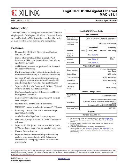
Introduction<br />
The <strong>LogiCORE</strong> <strong>IP</strong> <strong>10</strong>-<strong>Gigabit</strong> <strong>Ethernet</strong> <strong>MAC</strong> core is a<br />
single-speed, full-duplex <strong>10</strong> Gb/s <strong>Ethernet</strong> Media<br />
Access Controller (<strong>MAC</strong>) solution enabling the design<br />
of high-speed <strong>Ethernet</strong> systems and subsystems.<br />
Features<br />
Designed to <strong>10</strong>-<strong>Gigabit</strong> <strong>Ethernet</strong> specification<br />
IEEE 802.3-2008<br />
Choice of external XGMII or internal FPGA<br />
interface to PHY layer (internal interface only on<br />
Spartan®-6 devices)<br />
AXI4-Stream protocol support on client transmit<br />
and receive interfaces.<br />
Cut-through operation with minimum buffering<br />
for maximum flexibility in client-side interfacing<br />
Supports Deficit Idle Count for maximum data<br />
throughput; maintains minimum IFG under all<br />
conditions and provides line rate performance<br />
Supports Deficit Idle Count with In-Band FCS and<br />
without In-Band FCS for all devices<br />
Configured and monitored through a AXI4-Lite<br />
Management Interface<br />
Comprehensive statistics gathering with statistic<br />
vector outputs<br />
Supports flow-control in both directions<br />
MDIO STA master interface to manage PHY layers<br />
Extremely customizable; trade resource usage<br />
against functionality<br />
Available under SignOnce license program<br />
Delivered through the <strong>Xilinx</strong>® CORE Generator<br />
software<br />
Supports VLAN, jumbo frames, and WAN mode<br />
(WAN mode not supported on Spartan-6 devices.)<br />
Custom Preamble mode<br />
Supports feature of transmitting and receiving<br />
packets programmed up to MTU (Maximum<br />
Transmission Unit) programmed on both sides<br />
respectively.<br />
<strong>LogiCORE</strong> <strong>IP</strong> <strong>10</strong>-<strong>Gigabit</strong> <strong>Ethernet</strong><br />
<strong>MAC</strong> <strong>v11.1</strong><br />
<strong>DS813</strong> March 1, 2011 Product Specification<br />
Supported<br />
Device Family 1<br />
Supported User<br />
Interfaces<br />
<strong>LogiCORE</strong> <strong>IP</strong> Facts Table<br />
Core Specifics<br />
Virtex-7, Kintex-7, Virtex-6, Spartan-6 2<br />
1. For a complete listing of supported devices, see the release notes<br />
for this core. Speed grades are -1 for Virtex-6 and -3 for Spartan-6<br />
devices.<br />
2. External XGMII interface and WAN mode not supported on<br />
Spartan-6 devices.<br />
Resources 3<br />
AXI4-Lite, AXI4-Stream<br />
Frequency<br />
Devices Slices LUTs FFs BUFGs Max. Freq.<br />
Virtex-7<br />
Kintex-7<br />
See Table 18<br />
Virtex-6 See Table 19<br />
Spartan-6 See Table 20<br />
Documentation<br />
Provided with Core<br />
3. Numbers are approximate for default configuration in<br />
Virtex-6 devices. See Table 18, Table 19 and Table 20 for a<br />
complete description of device utilization by configuration and<br />
device family.<br />
© Copyright 2011. <strong>Xilinx</strong>, Inc. XILINX, the <strong>Xilinx</strong> logo, Artix, ISE, Kintex, Spartan, Virtex, and other designated brands included herein are trademarks of <strong>Xilinx</strong> in the<br />
United States and other countries. The PowerPC name and logo are registered trademarks of IBM Corp. and used under license. All other trademarks are the<br />
property of their respective owners.<br />
<strong>DS813</strong> March 1, 2011 www.xilinx.com 1<br />
Product Specification<br />
156.25<br />
MHz<br />
Product Specification<br />
User Guide<br />
Design Files NGC netlist<br />
Example Design VHDL and Verilog<br />
Test Bench VHDL and Verilog<br />
Constraints File UCF<br />
Simulation<br />
Model<br />
VHDL/Verilog<br />
Design Entry<br />
Tools<br />
Simulation<br />
Tested Design Tools<br />
ISE software v13.1<br />
Mentor Graphics ModelSim v6.6d<br />
Cadence Incisive Enterprise Simulator (IES)<br />
v<strong>10</strong>.2<br />
Synopsys VCS and VCS MX 20<strong>10</strong>.06<br />
Synthesis Tools XST 13.1<br />
Support<br />
Provided by <strong>Xilinx</strong>, Inc.
Applications<br />
<strong>LogiCORE</strong> <strong>IP</strong> <strong>10</strong>-<strong>Gigabit</strong> <strong>Ethernet</strong> <strong>MAC</strong> <strong>v11.1</strong><br />
Figure 1 shows a typical <strong>Ethernet</strong> system architecture and the <strong>10</strong>-<strong>Gigabit</strong> <strong>Ethernet</strong> <strong>MAC</strong> core within it. The <strong>MAC</strong><br />
and all the blocks to the right are defined in <strong>Ethernet</strong> IEEE specifications.<br />
X-Ref Target - Figure 1<br />
Figure 2 shows the <strong>10</strong>-<strong>Gigabit</strong> <strong>Ethernet</strong> <strong>MAC</strong> core connected to a physical layer (PHY) device, for example, an<br />
optical module using the XGMII interface.<br />
X-Ref Target - Figure 2<br />
TCP <strong>IP</strong> FIFO<br />
I/F<br />
User<br />
Logic<br />
(FIFO<br />
Example<br />
Design)<br />
<strong>MAC</strong> PCS WIS PMA PMD<br />
Figure 1: Typical <strong>Ethernet</strong> System Architecture<br />
<strong>10</strong>-<strong>Gigabit</strong><br />
<strong>Ethernet</strong><br />
<strong>MAC</strong> Core<br />
DDR<br />
Regs<br />
MDIO<br />
Optical Module<br />
with XGMII I/F<br />
Figure 2: <strong>10</strong>-<strong>Gigabit</strong> <strong>Ethernet</strong> <strong>MAC</strong> Core Connected to PHY with XGMII Interface<br />
<strong>DS813</strong> March 1, 2011 www.xilinx.com 2<br />
Product Specification
<strong>LogiCORE</strong> <strong>IP</strong> <strong>10</strong>-<strong>Gigabit</strong> <strong>Ethernet</strong> <strong>MAC</strong> <strong>v11.1</strong><br />
The <strong>10</strong>-<strong>Gigabit</strong> <strong>Ethernet</strong> <strong>MAC</strong> core is designed to be easily attached to the <strong>Xilinx</strong> <strong>IP</strong> XAUI core, the <strong>Xilinx</strong> <strong>IP</strong> RXAUI<br />
core, and the <strong>Xilinx</strong> <strong>IP</strong> <strong>10</strong>G <strong>Ethernet</strong> PCS/PMA. Figure 3 illustrates the <strong>10</strong>-<strong>Gigabit</strong> <strong>Ethernet</strong> <strong>MAC</strong> and XAUI cores in<br />
a system using an XPAK optical module.<br />
X-Ref Target - Figure 3<br />
User<br />
Logic<br />
(FIFO<br />
Example<br />
Design)<br />
<strong>10</strong>-<strong>Gigabit</strong><br />
<strong>Ethernet</strong><br />
<strong>MAC</strong> Core<br />
Figure 3: <strong>10</strong>-<strong>Gigabit</strong> <strong>Ethernet</strong> <strong>MAC</strong> Core Used with <strong>Xilinx</strong> XAUI Core<br />
Functional Description<br />
XAUI<br />
Core<br />
XPAK Optical Module<br />
low speed management signals<br />
Figure 4 illustrates a block diagram of the <strong>10</strong>-<strong>Gigabit</strong> <strong>Ethernet</strong> <strong>MAC</strong> core implementation. The major functional<br />
blocks of the core include the following:<br />
AXI4-Stream client-side interface: Designed for simple attachment of user logic<br />
Transmitter<br />
Receiver<br />
Flow Control block: Implements both Receive Flow Control and Transmit Flow Control<br />
Reconciliation Sublayer (RS): Processes XGMII Local Fault and Remote Fault messages and handles DDR<br />
conversion<br />
AXI4-Lite management interface and MDIO (optional)<br />
Statistics counters (optional)<br />
XGMII interface: Connection to the physical layer device or logic<br />
<strong>DS813</strong> March 1, 2011 www.xilinx.com 3<br />
Product Specification
X-Ref Target - Figure 4<br />
<br />
<br />
<br />
<br />
<br />
<br />
<br />
<br />
<br />
<br />
<br />
<br />
<br />
<br />
<br />
<br />
<br />
<br />
<br />
<br />
<br />
<br />
<br />
<br />
<br />
Figure 4: Implementation of the <strong>10</strong>-<strong>Gigabit</strong> <strong>Ethernet</strong> <strong>MAC</strong> Core<br />
<strong>LogiCORE</strong> <strong>IP</strong> <strong>10</strong>-<strong>Gigabit</strong> <strong>Ethernet</strong> <strong>MAC</strong> <strong>v11.1</strong><br />
<strong>DS813</strong> March 1, 2011 www.xilinx.com 4<br />
Product Specification
Core Interfaces<br />
AXI4-Stream Interface: Transmit<br />
<strong>LogiCORE</strong> <strong>IP</strong> <strong>10</strong>-<strong>Gigabit</strong> <strong>Ethernet</strong> <strong>MAC</strong> <strong>v11.1</strong><br />
The client-side interface on the transmit side of XG<strong>MAC</strong> supports the AXI4-Stream specification. It has a 64-bit<br />
datapath with eight control bits to delineate bytes within the 64-bit port. Additionally, there are signals to<br />
handshake the transfer of data into the core. An example design which includes source code for a FIFO with an<br />
AXI4-Stream interface is provided with the core generated by CORE Generator software.<br />
Table 1 defines the signals.<br />
Table 1: Transmit AXI4-Stream Interface Port Description<br />
Name Direction Description<br />
tx_axis_aresetn IN AXI4-Stream Active low reset for Transmit path XG<strong>MAC</strong>.<br />
tx_axis_tdata[63:0] IN AXI4-Stream <strong>Data</strong> to XG<strong>MAC</strong>.<br />
tx_axis_tkeep[7:0] IN AXI4-Stream <strong>Data</strong> Control to XG<strong>MAC</strong>.<br />
tx_axis_tvalid IN AXI4-Stream <strong>Data</strong> Valid input to XG<strong>MAC</strong>.<br />
tx_axis_tuser IN AXI4-Stream User signal used to indicate explicit underrun<br />
tx_ifg_delay[7:0] IN Out-of-band signal used to configure Inter-frame gap adjustment between<br />
transmitted packets.<br />
tx_axis_tlast IN AXI4-Stream signal to XG<strong>MAC</strong> indicating End of <strong>Ethernet</strong> Packet.<br />
tx_axis_tready OUT AXI4-Stream acknowledge signal from XG<strong>MAC</strong> to indicate to start the <strong>Data</strong> transfer.<br />
AXI4-Stream Interface: Receive<br />
The client-side interface on receive side of XG<strong>MAC</strong> supports the AXI4-Stream specification. It has a 64-bit datapath<br />
with eight control bits to delineate bytes within the 64-bit port. Additionally, there are signals to indicate to the user<br />
logic the validity of the previous frame received. Table 2 defines the signals.<br />
Table 2: Receive AXI4-Stream Interface Port Description<br />
Name Direction Description<br />
rx_axis_aresetn IN AXI4-Stream Active low reset for Receive path XG<strong>MAC</strong>.<br />
rx_axis_tdata[63:0] OUT AXI4-Stream <strong>Data</strong> from XG<strong>MAC</strong> to upper layer.<br />
rx_axis_tkeep[7:0] OUT AXI4-Stream <strong>Data</strong> Control from XG<strong>MAC</strong> to upper layer.<br />
rx_axis_tvalid OUT AXI4-Stream <strong>Data</strong> Valid from XG<strong>MAC</strong>.<br />
rx_axis_tuser OUT AXI4-Stream User Sideband Interface from XG<strong>MAC</strong>.<br />
'1' indicates that a good packet has been received.<br />
'0' indicates that a bad packet has been received.<br />
rx_axis_tlast OUT AXI4-Stream signal from XG<strong>MAC</strong> indicating an end of packet.<br />
<strong>DS813</strong> March 1, 2011 www.xilinx.com 5<br />
Product Specification
Flow Control Interface<br />
<strong>LogiCORE</strong> <strong>IP</strong> <strong>10</strong>-<strong>Gigabit</strong> <strong>Ethernet</strong> <strong>MAC</strong> <strong>v11.1</strong><br />
The flow control interface is used to initiate the transmission of flow control frames from the core. The ports<br />
associated with this interface are shown in Table 3.<br />
Table 3: Flow Control Interface Port Description<br />
Name Direction Description<br />
pause_req Input Request that a flow control frame is emitted from the <strong>MAC</strong> core.<br />
pause_val[15:0] Input Pause value field for flow control frame to be sent when pause_req asserted.<br />
XGMII Interface or 64-bit SDR PHY Interface<br />
The PHY interface can be a 32-bit DDR XGMII interface or a 64-bit SDR interface, depending on the customization<br />
of the core. This interface is used to connect to the physical layer, whether this is a separate device or implemented<br />
in the FPGA beside the <strong>MAC</strong> core. Table 4 and Table 5 show the ports associated with this interface.<br />
Table 4: 32-bit XGMII PHY Interface Port Descriptions<br />
Name Direction Description<br />
xgmii_tx_clk Output Forwarded clock to PHY device.<br />
xgmii_txd[31:0] Output Transmit data to PHY; double data rate (DDR) source centred on xgmii_tx_clk.<br />
xgmii_txc[3:0] Output Transmit control to PHY; DDR source-centred on xgmii_tx_clk.<br />
xgmii_rx_clk Input Inbound clock from PHY device.<br />
xgmii_rxd[31:0] Input Received data from PHY; DDR source-centred on xgmii_rx_clk.<br />
xgmii_rxc[3:0] Input Received control from PHY; DDR source-centred on xgmii_rx_clk.<br />
Table 5: 64-bit SDR PHY Interface Port Descriptions<br />
Name Direction Description<br />
xgmii_txd[63:0] Output Transmit data to PHY. Synchronous to rising edge of tx_clk.<br />
xgmii_txc[7:0] Output Transmit control to PHY. Synchronous to rising edge of tx_clk.<br />
xgmii_rx_clk Input Inbound clock from PHY.<br />
xgmii_rxd[63:0] Input Received data from PHY. Synchronous to rising edge of xgmii_rx_clk.<br />
xgmii_rxc[7:0] Input Received control from PHY. Synchronous to rising edge of xgmii_rx_clk.<br />
<strong>DS813</strong> March 1, 2011 www.xilinx.com 6<br />
Product Specification
Management Interface<br />
<strong>LogiCORE</strong> <strong>IP</strong> <strong>10</strong>-<strong>Gigabit</strong> <strong>Ethernet</strong> <strong>MAC</strong> <strong>v11.1</strong><br />
Configuration of the core, access to the statistics block, access to the MDIO port, and access to the interrupt block<br />
can be provided through the Management Interface. The AXI4-Lite Wrapper allows the <strong>MAC</strong> netlist to be<br />
connected to an AXI4-Lite Interface and drives the <strong>Ethernet</strong> <strong>MAC</strong> netlist through a processor independent <strong>IP</strong>IF.<br />
Table 6 defines the ports associated with the Management Interface. The Management Interface can be omitted at<br />
core customization. In this case, the available configuration signals would be used. See Configuration and Status<br />
Signals.<br />
Table 6: AXI4-Lite Interface Port Description<br />
Name Direction Description<br />
s_axi_aclk IN AXI4-Lite clock. Range between <strong>10</strong> MHz and 156.25 MHz<br />
s_axi_aresetn IN Asynchronous active low reset<br />
s_axi_awaddr[31:0] IN Write address Bus<br />
s_axi_awvalid IN Write address valid<br />
s_axi_awready OUT Write address acknowledge<br />
s_axi_wdata[31:0] IN Write data bus<br />
s_axi_wvalid IN Write data valid<br />
s_axi_wready OUT Write data acknowledge<br />
s_axi_bresp[1:0] OUT Write transaction response<br />
s_axi_bvalid OUT Write response valid<br />
s_axi_bready IN Write response acknowledge<br />
s_axi_araddr[31:0] IN Read address Bus<br />
s_axi_arvalid IN Read address valid<br />
s_axi_arready OUT Read address acknowledge<br />
s_axi_rdata[31:0] OUT Read data output<br />
s_axi_rresp[1:0] OUT Read data response<br />
s_axi_rvalid OUT Read data/response valid<br />
s_axi_rready IN Read data acknowledge<br />
<strong>DS813</strong> March 1, 2011 www.xilinx.com 7<br />
Product Specification
Statistic Counters<br />
<strong>LogiCORE</strong> <strong>IP</strong> <strong>10</strong>-<strong>Gigabit</strong> <strong>Ethernet</strong> <strong>MAC</strong> <strong>v11.1</strong><br />
During operation, the <strong>MAC</strong> core collects statistics on the success and failure of various operations for processing by<br />
network management entities elsewhere in the system. These statistics are accessed through the Management<br />
Interface. A list of statistics is shown in Table 7.<br />
Table 7: Statistics Counters<br />
1 Received bytes<br />
2 Transmitted bytes<br />
3 Undersize frames received<br />
4 Fragment frames received<br />
5 64 byte frames received OK<br />
6 65-127 byte frames received OK<br />
7 128-255 byte frames received OK<br />
8 256-511 byte frames received OK<br />
9 512-<strong>10</strong>23 byte frames received OK<br />
<strong>10</strong> <strong>10</strong>24-MaxFrameSize byte frames received OK<br />
11 Oversize frames received OK<br />
12 64 byte frames transmitted OK<br />
13 65-127 byte frames transmitted OK<br />
14 128-255 byte frames transmitted OK<br />
15 256-511 byte frames transmitted OK<br />
16 512-<strong>10</strong>23 byte frames transmitted OK<br />
17 <strong>10</strong>24-MaxFrameSize byte frames transmitted OK<br />
18 Oversize frames transmitted OK<br />
19 Frames received OK<br />
20 Frame Check Sequence errors<br />
21 Broadcast frames received OK<br />
22 Multicast frames received OK<br />
23 Control frames received OK<br />
24 Length/Type out of range<br />
25 VLAN tagged frames received OK<br />
26 PAUSE frames received OK<br />
27 Control frames received with unsupported opcode<br />
28 Frames transmitted OK<br />
29 Broadcast frames transmitted OK<br />
30 Multicast frames transmitted OK<br />
31 Underrun errors<br />
32 Control frames transmitted OK<br />
33 VLAN tagged frames transmitted OK<br />
34 PAUSE frames transmitted OK<br />
The statistic counters are an optional block of the <strong>10</strong>-<strong>Gigabit</strong> <strong>Ethernet</strong> <strong>MAC</strong> core.<br />
<strong>DS813</strong> March 1, 2011 www.xilinx.com 8<br />
Product Specification
Configuration Registers<br />
<strong>LogiCORE</strong> <strong>IP</strong> <strong>10</strong>-<strong>Gigabit</strong> <strong>Ethernet</strong> <strong>MAC</strong> <strong>v11.1</strong><br />
After the core is powered up and reset, the user application can reconfigure some of the core parameters from their<br />
default values, such as flow control operation and WAN mode. Configuration registers can be written and read at<br />
any time; however, changes may only take effect during the next interframe gap period. Exceptions to this include<br />
the soft reset registers which take effect immediately.<br />
Configuration of the <strong>10</strong>-<strong>Gigabit</strong> <strong>Ethernet</strong> <strong>MAC</strong> core is performed through a bank of registers accessed through the<br />
Management Interface. The configuration registers in this bank are shown Table 8. Their addresses and contents are<br />
described in the <strong>LogiCORE</strong> <strong>IP</strong> <strong>10</strong>-<strong>Gigabit</strong> <strong>Ethernet</strong> <strong>MAC</strong> v 11.1 User Guide (UG773).<br />
Table 8: Configuration Registers<br />
1 Receiver Configuration Word 0<br />
2 Receiver Configuration Word 1<br />
3 Transmitter Configuration<br />
4 Flow Control Configuration<br />
5 Reconciliation Sublayer Configuration<br />
6 Receiver MTU Configuration word<br />
7 Transmitter MTU Configuration word<br />
8 Version Register<br />
9 Capability Register<br />
MDIO STA Master<br />
The MDIO STA master interface implemented in the <strong>10</strong>-<strong>Gigabit</strong> <strong>Ethernet</strong> <strong>MAC</strong> core is an STA entity (as defined by<br />
IEEE Std.802.3-2008 that can initiate transactions to one or more attached physical layer MDIO Managed Devices<br />
(MMDs). The MDIO registers are shown in Table 9. Their addresses and contents are described in the <strong>LogiCORE</strong> <strong>IP</strong><br />
<strong>10</strong>-<strong>Gigabit</strong> <strong>Ethernet</strong> <strong>MAC</strong> v 11.1 User Guide (UG773).<br />
Table 9: MDIO Registers<br />
1 MDIO Configuration Word 0<br />
2 MDIO Configuration Word 1<br />
3 MDIO Transmit <strong>Data</strong> Word<br />
4 MDIO Receive <strong>Data</strong> Word<br />
If the Management Interface is omitted from the core, the MDIO interface is also omitted.<br />
<strong>DS813</strong> March 1, 2011 www.xilinx.com 9<br />
Product Specification
Interrupt Block<br />
<strong>LogiCORE</strong> <strong>IP</strong> <strong>10</strong>-<strong>Gigabit</strong> <strong>Ethernet</strong> <strong>MAC</strong> <strong>v11.1</strong><br />
An Interrupt function is provided in the <strong>10</strong>-<strong>Gigabit</strong> <strong>Ethernet</strong> <strong>MAC</strong> core to assert an interrupt when a pending<br />
MDIO transaction is completed. Interrupt registers are shown in Table <strong>10</strong>. Their addresses and contents are<br />
described in the <strong>LogiCORE</strong> <strong>IP</strong> <strong>10</strong>-<strong>Gigabit</strong> <strong>Ethernet</strong> <strong>MAC</strong> v 11.1 User Guide (UG773).<br />
Table <strong>10</strong>: Interrupt Registers<br />
1 Interrupt Status Register<br />
2 Interrupt Pending Register<br />
3 Interrupt Enable Register<br />
4 Interrupt Acknowledge Register<br />
Configuration and Status Signals<br />
If the Management Interface is omitted at core customization time, a configuration vector for each transmitter and<br />
receiver interface and a status vector is exposed by the core. This allows you to configure the core by statically or<br />
dynamically driving the constituent bits of these ports. Table 11 and Table 12 describe the configuration signals for<br />
transmitter and receiver and Table 13 describes the status signals. For more information about the use of the<br />
configuration vector, see the <strong>10</strong>-<strong>Gigabit</strong> <strong>Ethernet</strong> <strong>MAC</strong> User Guide.<br />
Table 11: Transmitter Configuration Signals<br />
Name Direction Description<br />
configuration_vector_tx[79:0] Input<br />
Bit 0: Transmitter reset<br />
Bit 1: Transmitter Enable<br />
Bit 2: Transmitter VLAN Enable<br />
Bit 3: Transmitter In Band FCS Enable<br />
Bit 4: Transmitter Jumbo Frame Enable<br />
Bit 5: Transmit Flow Control enable<br />
Bit 6: Reserved<br />
Bit 7: Tx preserve preamble enable<br />
Bit 8: Transmitter IFG Adjust enable<br />
Bit 9: Transmitter LAN/WAN<br />
Bit <strong>10</strong>: Transmit Deficit Idle Count<br />
Bit 11 to 13: Reserved<br />
Bit 14: Transmitter Max Frame Enable<br />
Bit 15: Reserved<br />
Bit 31 to 16: Transmitter Max Frame Length[15:0]<br />
Bit 79 to 32: Transmitter Pause Frame Source Address<br />
<strong>DS813</strong> March 1, 2011 www.xilinx.com <strong>10</strong><br />
Product Specification
Table 12: Receiver Configuration Signals<br />
Statistic Vectors<br />
Name Direction Description<br />
configuration_vector_rx[79:0] Input<br />
Table 13: Status Signals<br />
Name Direction Description<br />
status_vector output<br />
<strong>LogiCORE</strong> <strong>IP</strong> <strong>10</strong>-<strong>Gigabit</strong> <strong>Ethernet</strong> <strong>MAC</strong> <strong>v11.1</strong><br />
Bit 0: Receiver reset<br />
Bit 1: Receiver Enable<br />
Bit 2: Receiver VLAN Enable<br />
Bit 3: Receiver In Band FCS Enable<br />
Bit 4: Receiver Jumbo Frame Enable<br />
Bit 5: ReceiveFlow Control enable<br />
Bit 6: Reserved<br />
Bit 7: Rx preserve preamble enable<br />
Bit 8: Receiver Length/Type Check Disable<br />
Bit 9: Control Frame Length Check Disable<br />
Bit <strong>10</strong>: RS fault inhibit<br />
Bit 11 to 13: Reserved<br />
Bit 14: Receiver Max Frame Enable<br />
Bit 15: Reserved<br />
Bit 31 to 16: Receiver Max Frame Length[15:0]<br />
Bit 79 to 32: Receiver Pause Frame Source Address<br />
In addition to the statistic counters described in Management Interface, there are two statistics vector outputs on the<br />
core netlist that are used to signal the core state. These vectors are actually used as the inputs of the counter logic<br />
internal to the core. So if you omit the statistic counters at the CORE Generator software customization stage, a<br />
relevant subset can be implemented in user logic. Table 14 identifies the signals. The contents of the vectors are<br />
defined in Table 15 and Table 16.<br />
Table 14: Statistic Vector Signals<br />
Bit 0: Local fault received<br />
Bit 1: Remote fault received<br />
Name Direction Description<br />
tx_statistics_vector[25:0] Output Aggregated statistics flags for transmitted frame<br />
tx_statistics_valid Output Valid strobe for tx_statistics_vector<br />
rx_statistics_vector[29:0] Output Aggregated statistics flags for received frames<br />
rx_statistics_valid Output Valid strobe for rx_statistics_vector<br />
<strong>DS813</strong> March 1, 2011 www.xilinx.com 11<br />
Product Specification
Table 15: Transmit Statistics Vector Contents<br />
tx_statistics_vector bits Name<br />
25 PAUSE_FRAME_TRANSMITTED<br />
24 to 21 BYTES_VALID<br />
20 VLAN_FRAME<br />
19 to 5 FRAME_LENGTH_COUNT<br />
4 CONTROL_FRAME<br />
3 UNDERRUN_FRAME<br />
2 MULTICAST_FRAME<br />
1 BROADCAST_FRAME<br />
0 SUCCESSFUL_FRAME<br />
Table 16: Receive Statistics Vector Contents<br />
rx_statistics_vector bits Name<br />
29 LEN_TYPE_RANGE<br />
28 BAD_OPCODE<br />
27 FLOW_CONTROL_FRAME<br />
26 to 23 BYTES_VALID<br />
22 VLAN_FRAME<br />
21 OUT_OF_BOUNDS<br />
20 CONTROL_FRAME<br />
19 to 5 FRAME_LENGTH_COUNT<br />
4 MULTICAST_FRAME<br />
3 BROADCAST_FRAME<br />
2 FCS_ERROR<br />
1 BAD_FRAME<br />
0 GOOD_FRAME<br />
<strong>LogiCORE</strong> <strong>IP</strong> <strong>10</strong>-<strong>Gigabit</strong> <strong>Ethernet</strong> <strong>MAC</strong> <strong>v11.1</strong><br />
<strong>DS813</strong> March 1, 2011 www.xilinx.com 12<br />
Product Specification
Clocks and Resets<br />
<strong>LogiCORE</strong> <strong>IP</strong> <strong>10</strong>-<strong>Gigabit</strong> <strong>Ethernet</strong> <strong>MAC</strong> <strong>v11.1</strong><br />
Table 17 describes the clock and reset ports present on the supplied example design. In the source code of the<br />
example design, other system clocks are derived from the gtx_clk and xgmii_rx_clk signals for use in the core<br />
logic. This clock arrangement can be customized in the user application as required.<br />
Table 17: Clock and Reset Ports<br />
Name Direction Description<br />
gtx_clk Input Global transmit clock; all other transmit clocks are derived from this clock<br />
xgmii_rx_clk Input XGMII receive clock; all receive clocks are derived from this clock<br />
reset Input Asynchronous reset<br />
rx_axis_aresetn Input AXI4-Stream Active low reset for Receive path XG<strong>MAC</strong>.<br />
tx_axis_aresetn Input AXI4-Stream Active low reset for Transmit path XG<strong>MAC</strong>.<br />
Verification<br />
The <strong>10</strong>-<strong>Gigabit</strong> <strong>Ethernet</strong> <strong>MAC</strong> core has been verified in simulation.<br />
Simulation<br />
A highly parameterizable transaction-based simulation test suite has been used to verify the core. Tests included:<br />
Configuration register access through Management Interface<br />
Local Fault and Remote Fault handling<br />
Frame transmission<br />
Frame reception<br />
CRC validity<br />
Handling of CRC errors<br />
Statistic counter access through Management Interface and validity of counts<br />
Statistic vector validity<br />
Initiating MDIO transactions through Management Interface<br />
Use of custom preamble field<br />
Variable Frame Length and MTU<br />
Hardware Verification<br />
The core has been used in a number of hardware test platforms at <strong>Xilinx</strong>, including the following:<br />
The core has been used in a test platform design with the <strong>Xilinx</strong> <strong>10</strong>-<strong>Gigabit</strong> <strong>Ethernet</strong> XAUI <strong>LogiCORE</strong> <strong>IP</strong>. This<br />
design comprises the <strong>MAC</strong>, XAUI, a ping loopback FIFO and a test pattern generator all under embedded<br />
PowerPC® processor control.<br />
This design has been used for conformance and interoperability testing at the University of New Hampshire<br />
Interoperability Lab.<br />
<strong>DS813</strong> March 1, 2011 www.xilinx.com 13<br />
Product Specification
Device Utilization<br />
Virtex-7 and Kintex-7 FPGAs<br />
<strong>LogiCORE</strong> <strong>IP</strong> <strong>10</strong>-<strong>Gigabit</strong> <strong>Ethernet</strong> <strong>MAC</strong> <strong>v11.1</strong><br />
Table 18: Device Utilization for the <strong>10</strong>-<strong>Gigabit</strong> <strong>Ethernet</strong> <strong>MAC</strong> Core (Virtex-7 and Kintex-7 FPGAs)<br />
Device Family Physical<br />
Interface<br />
virtex7<br />
kintex7<br />
XGMII<br />
Internal<br />
XGMII<br />
Internal<br />
Virtex-6 FPGAs<br />
Parameter Values Resource Usage<br />
Management<br />
Interface<br />
TRUE<br />
Statistic<br />
Counters<br />
Slices LUTs FFs BUFGs<br />
TRUE 1871 3667 4251 2<br />
FALSE 1505 29<strong>10</strong> 3334 2<br />
FALSE FALSE 1353 2682 2921 2<br />
TRUE<br />
TRUE 1966 3668 4395 2<br />
FALSE 1606 2922 3479 2<br />
FALSE FALSE 1374 2683 3066 2<br />
TRUE<br />
TRUE 1965 3655 4250 2<br />
FALSE 1529 2920 3335 2<br />
FALSE FALSE 1326 2681 2921 2<br />
TRUE<br />
TRUE 1934 3728 4178 2<br />
FALSE 1518 2982 3262 2<br />
FALSE FALSE 1334 2754 2850 2<br />
Table 19 provides approximate utilization figures for various core options when a single instance of the core is<br />
instantiated in a Virtex®-6 device.<br />
Utilization figures are obtained by implementing the block-level wrapper for the core. This wrapper is part of the<br />
example design and connects the core to the selected physical interface.<br />
Table 19: Device Utilization for the <strong>10</strong>-<strong>Gigabit</strong> <strong>Ethernet</strong> <strong>MAC</strong> Core (Virtex-6 FPGAs)<br />
Device<br />
Family<br />
virtex6<br />
Parameter Values<br />
Physical<br />
Interface<br />
XGMII<br />
Internal<br />
Management<br />
Interface<br />
TRUE<br />
Statistic<br />
Counters<br />
Resource Usage<br />
Slices LUTs FFs BUFGs<br />
TRUE 1920 3665 4<strong>10</strong>7 2<br />
FALSE 1465 2911 3191 2<br />
FALSE FALSE 1271 2674 2777 2<br />
TRUE<br />
TRUE 1947 3666 4<strong>10</strong>7 2<br />
FALSE 1485 2912 3191 2<br />
FALSE FALSE 1300 2675 2778 2<br />
<strong>DS813</strong> March 1, 2011 www.xilinx.com 14<br />
Product Specification
Spartan-6 FPGAs<br />
<strong>LogiCORE</strong> <strong>IP</strong> <strong>10</strong>-<strong>Gigabit</strong> <strong>Ethernet</strong> <strong>MAC</strong> <strong>v11.1</strong><br />
Table 20 provides approximate utilization figures for various core options when a single instance of the core is<br />
instantiated in a Spartan-6 device.<br />
Utilization figures are obtained by implementing the block-level wrapper for the core. This wrapper is part of the<br />
example design and connects the core to the selected physical interface.<br />
Table 20: Device Utilization for the <strong>10</strong>-<strong>Gigabit</strong> <strong>Ethernet</strong> <strong>MAC</strong> Core (Spartan-6 FPGAs)<br />
Device Family<br />
References<br />
[1] IEEE Standard 802.3-2008, “Carrier Sense Multiple Access with Collision Detection (CSMA/CD) Access Method<br />
and Physical Layer Specifications.”<br />
Support<br />
Visit www.xilinx.com/support/ for technical support. <strong>Xilinx</strong> provides technical support for this <strong>LogiCORE</strong> <strong>IP</strong><br />
product when used as described in product documentation.<br />
<strong>Xilinx</strong> cannot guarantee timing, functionality, or support of product if implemented in devices that are not listed in<br />
the documentation or if customized beyond that allowed in the product documentation, or if any changes are made<br />
in sections of the design marked as DO NOT MODIFY.<br />
Ordering Information<br />
Parameter Values Resource Usage<br />
Physical<br />
Interface<br />
spartan6 Internal<br />
Management<br />
Interface<br />
TRUE<br />
Statistic<br />
Counters<br />
Slices LUTs FFs BUFGs<br />
TRUE 1925 3499 4177 1<br />
FALSE 1538 2787 3264 1<br />
FALSE FALSE 1361 2544 2849 1<br />
This <strong>Xilinx</strong> <strong>LogiCORE</strong> <strong>IP</strong> module is provided under the SignOnce <strong>IP</strong> Site License. Two free evaluation licenses are<br />
provided: The Simulation Only license is provided with the CORE Generator software, and the Full System<br />
Hardware Evaluation license, which lets you test your designs in hardware for a limited period of time, can be<br />
downloaded from the <strong>10</strong>GE<strong>MAC</strong> product page.<br />
For full access to all core functionality, both in simulation and in hardware, you must purchase the core. The <strong>Xilinx</strong><br />
CORE Generator system is bundled with the <strong>Xilinx</strong> ISE® Design Suite software at no additional charge.<br />
Contact your local <strong>Xilinx</strong> sales representative for pricing and availability of <strong>Xilinx</strong> <strong>LogiCORE</strong> <strong>IP</strong> modules and<br />
software. Information about additional <strong>Xilinx</strong> <strong>LogiCORE</strong> <strong>IP</strong> modules is available on the <strong>Xilinx</strong> <strong>IP</strong> Center.<br />
<strong>DS813</strong> March 1, 2011 www.xilinx.com 15<br />
Product Specification
List of Acronyms<br />
Acronym Description<br />
AXI Advanced eXtensible Interface<br />
<strong>LogiCORE</strong> <strong>IP</strong> <strong>10</strong>-<strong>Gigabit</strong> <strong>Ethernet</strong> <strong>MAC</strong> <strong>v11.1</strong><br />
CRC Cyclic Redundancy Check<br />
CSMA/CD Carrier Sense Multiple Access with Collision Detection<br />
DCM Digital Clock Manager<br />
DDR Double <strong>Data</strong> Rate<br />
EDIF Electronic Design Interchange Format<br />
FCS Frame Check Sequence<br />
FF Flip-Flop<br />
FIFO First In First Out<br />
FPGA Field Programmable Gate Array<br />
Gb/s <strong>Gigabit</strong>s per second<br />
IES Incisive Enterprise Simulator<br />
IFG Interframe GAP<br />
<strong>IP</strong> Intellectual Property<br />
ISE Integrated Software Environment<br />
LUT Lookup Table<br />
<strong>MAC</strong> Media Access Controller<br />
MDIO Management <strong>Data</strong> Input/Output<br />
MHz Mega Hertz<br />
MMD MDIO Managed Devices<br />
MTU Maximum Transmission Unit<br />
NDA Non-Disclosure Agreement<br />
NGC Native Generic Circuit<br />
PHY physical-side interface<br />
RAM Random Access Memory<br />
RS Reconciliation Sublayer<br />
SDR Single <strong>Data</strong> Rate<br />
STA Station Management Entity<br />
UCF User Constraints File<br />
VCS Verilog Compiled Simulator (Synopsys)<br />
VHDL VHSIC Hardware Description Language (VHSIC an acronym for Very High-Speed Integrated Circuits)<br />
VLAN Virtual LAN (Local Area Network)<br />
WAN Wide Area Network<br />
XAUI eXtended Attachment Unit Interface<br />
XGMII <strong>10</strong>-<strong>Gigabit</strong> Media Independent Interface<br />
XPAK Expansion Pack<br />
XST <strong>Xilinx</strong> Synthesis Technology<br />
<strong>DS813</strong> March 1, 2011 www.xilinx.com 16<br />
Product Specification
Revision History<br />
Date Version Revision<br />
03/01/<strong>10</strong> 1.1 Initial Release<br />
Notice of Disclaimer<br />
<strong>LogiCORE</strong> <strong>IP</strong> <strong>10</strong>-<strong>Gigabit</strong> <strong>Ethernet</strong> <strong>MAC</strong> <strong>v11.1</strong><br />
<strong>Xilinx</strong> is providing this product documentation, hereinafter “Information,” to you “AS IS” with no warranty of any kind, express<br />
or implied. <strong>Xilinx</strong> makes no representation that the Information, or any particular implementation thereof, is free from any<br />
claims of infringement. You are responsible for obtaining any rights you may require for any implementation based on the<br />
Information. All specifications are subject to change without notice. XILINX EXPRESSLY DISCLAIMS ANY WARRANTY<br />
WHATSOEVER WITH RESPECT TO THE ADEQUACY OF THE INFORMATION OR ANY IMPLEMENTATION BASED<br />
THEREON, INCLUDING BUT NOT LIMITED TO ANY WARRANTIES OR REPRESENTATIONS THAT THIS<br />
IMPLEMENTATION IS FREE FROM CLAIMS OF INFRINGEMENT AND ANY IMPLIED WARRANTIES OF<br />
MERCHANTABILITY OR FITNESS FOR A PARTICULAR PURPOSE. Except as stated herein, none of the Information may be<br />
copied, reproduced, distributed, republished, downloaded, displayed, posted, or transmitted in any form or by any means<br />
including, but not limited to, electronic, mechanical, photocopying, recording, or otherwise, without the prior written consent of<br />
<strong>Xilinx</strong>.<br />
<strong>DS813</strong> March 1, 2011 www.xilinx.com 17<br />
Product Specification


