Wankel Engines Project Report edited .pdf - 123SeminarsOnly
Wankel Engines Project Report edited .pdf - 123SeminarsOnly
Wankel Engines Project Report edited .pdf - 123SeminarsOnly

You also want an ePaper? Increase the reach of your titles
YUMPU automatically turns print PDFs into web optimized ePapers that Google loves.
The pressure in a working chamber in the combustion stroke is higher than that in the<br />
compression stroke till the apex seal slightly passes the minor axis. Such a difference will<br />
soon disappear bringing a higher pressure to the working chamber in the compression<br />
stroke. This means that the variation in gas pressure acting on the side of the apex seal will<br />
cause it to move back and forth in its groove. In addition to this gas pressure, various kinds<br />
of inertia force to be caused by the planetary motion of the apex seal with the rotor must be<br />
taken into consideration with respect to the motion of the apex seal in its groove.<br />
MATERIAL OF APEX SEAL<br />
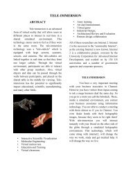
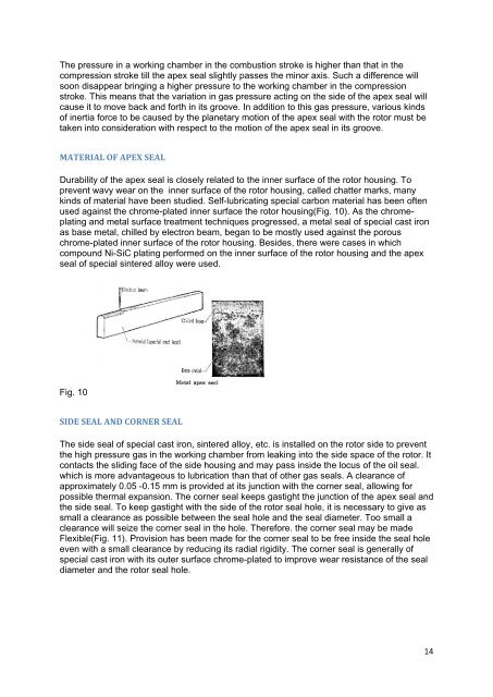
Durability of the apex seal is closely related to the inner surface of the rotor housing. To<br />
prevent wavy wear on the inner surface of the rotor housing, called chatter marks, many<br />
kinds of material have been studied. Self-lubricating special carbon material has been often<br />
used against the chrome-plated inner surface the rotor housing(Fig. 10). As the chromeplating<br />
and metal surface treatment techniques progressed, a metal seal of special cast iron<br />
as base metal, chilled by electron beam, began to be mostly used against the porous<br />
chrome-plated inner surface of the rotor housing. Besides, there were cases in which<br />
compound Ni-SiC plating performed on the inner surface of the rotor housing and the apex<br />
seal of special sintered alloy were used.<br />
Fig. 10<br />
SIDE SEAL AND CORNER SEAL<br />
The side seal of special cast iron, sintered alloy, etc. is installed on the rotor side to prevent<br />
the high pressure gas in the working chamber from leaking into the side space of the rotor. It<br />
contacts the sliding face of the side housing and may pass inside the locus of the oil seal.<br />
which is more advantageous to lubrication than that of other gas seals. A clearance of<br />
approximately 0.05 -0.15 mm is provided at its junction with the corner seal, allowing for<br />
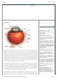
possible thermal expansion. The corner seal keeps gastight the junction of the apex seal and<br />
the side seal. To keep gastight with the side of the rotor seal hole, it is necessary to give as<br />
small a clearance as possible between the seal hole and the seal diameter. Too small a<br />
clearance will seize the corner seal in the hole. Therefore. the corner seal may be made<br />
Flexible(Fig. 11). Provision has been made for the corner seal to be free inside the seal hole<br />
even with a small clearance by reducing its radial rigidity. The corner seal is generally of<br />
special cast iron with its outer surface chrome-plated to improve wear resistance of the seal<br />
diameter and the rotor seal hole.<br />
14