Pressure control in band-saw hydraulic system using the fuzzy logic
Pressure control in band-saw hydraulic system using the fuzzy logic
Pressure control in band-saw hydraulic system using the fuzzy logic

Create successful ePaper yourself
Turn your PDF publications into a flip-book with our unique Google optimized e-Paper software.
<strong>Pressure</strong> <strong>control</strong> <strong>in</strong> <strong>band</strong>-<strong>saw</strong><br />
<strong>hydraulic</strong> <strong>system</strong> us<strong>in</strong>g <strong>the</strong> <strong>fuzzy</strong> <strong>logic</strong><br />
GRZEGORZ FILO<br />
List of notations<br />
A sil – Area of <strong>hydraulic</strong> cyl<strong>in</strong>der piston, m 2<br />
A sz – Area of piston gap <strong>in</strong> proportional relief valve,<br />
m 2<br />
B – Bulk modulus, MPa<br />
c spr , c s – Spr<strong>in</strong>g stiffness, N/m<br />
e – Normalized value of <strong>control</strong> error<br />
∆e – Change of normalized <strong>control</strong> error<br />
F el – Electromagnetic force, N<br />
F h – Hydraulic cyl<strong>in</strong>der force, N<br />
F hs-s , F hs-p – Hydrostatic forces, N<br />
F hd-s , F hd-p – Hydrodynamic forces, N<br />
F s0 – Initial spr<strong>in</strong>g tension, N<br />
G c – Force of gravity, N<br />
g p – Width of cutt<strong>in</strong>g <strong>band</strong>, m<br />
J – Moment of <strong>in</strong>ertia, kg·m 2<br />
K – Factor of proportionality, N/V<br />
M spr – Moment of spr<strong>in</strong>g, N·m<br />
m s , m p – Mass of piston and pilot, kg<br />
M sc – Moment of gravity, N·m<br />
M sil – Moment of <strong>hydraulic</strong> cyl<strong>in</strong>der, N·m<br />
M Py – Moment of normal component of cutt<strong>in</strong>g<br />
force, N·m<br />
M Pz – Moment of tangent component of cutt<strong>in</strong>g<br />
force, N·m<br />
N – Number of cutt<strong>in</strong>g teeth<br />
P y – Normal component of cutt<strong>in</strong>g force, N<br />
P z – Tangent component of cutt<strong>in</strong>g force, N<br />
P y1 – Normal component of cutt<strong>in</strong>g force act<strong>in</strong>g on<br />
s<strong>in</strong>gle tooth, N<br />
P 23 – Distance between po<strong>in</strong>ts, m<br />
p sil – Hydraulic cyl<strong>in</strong>der pressure, MPa<br />
p vf – Vertical feed of s<strong>in</strong>gle cutt<strong>in</strong>g tooth, mm/s<br />
p zl – <strong>Pressure</strong> <strong>in</strong> return l<strong>in</strong>e, MPa<br />
Q sil – Volumetric flow rate, m 3 /s<br />
r 23 – Arm of a spr<strong>in</strong>g force, m<br />
R c – Arm of force of gravity, m<br />
R h – Arm of a <strong>hydraulic</strong> cyl<strong>in</strong>der force, m<br />
U – Control signal, V<br />
V sil – Volume under <strong>hydraulic</strong> cyl<strong>in</strong>der piston, m 3<br />
V 0 – Volume of <strong>hydraulic</strong> pipes, m 3<br />
x s , x p – Position of piston and pilot, m<br />
x 0 – Initial spr<strong>in</strong>g tension<br />
β – Resistance coefficient, Nm·s/rad<br />
ϕ – Rotation angle of cutt<strong>in</strong>g head, rad<br />
µ sz – Flow coefficient<br />
ρ – Liquid density, kg/m 3<br />
ω – Angular velocity of cutt<strong>in</strong>g head, rad/s<br />
Currently, a trend <strong>in</strong> <strong>the</strong> development of mach<strong>in</strong>e<br />
tools, such as cutt<strong>in</strong>g mach<strong>in</strong>es, gr<strong>in</strong>ders, percussive<br />
hammers etc., towards a higher dynamical per-<br />
Dr <strong>in</strong>˝. Grzegorz Filo jest adiunktem w Instytucie Informatyki<br />
Stosowanej na Wydziale Mechanicznym Politechniki<br />
Krakowskiej.<br />
formance can be observed. It is a result of progress<br />
which was achieved on <strong>the</strong> one hand <strong>in</strong> material<br />
science and on <strong>the</strong> o<strong>the</strong>r hand <strong>in</strong> power transmission<br />
and <strong>control</strong> <strong>system</strong>s. Electrical, pneumatic and <strong>hydraulic</strong><br />
drives can be now <strong>control</strong>led with higher<br />
speed and accuracy. In this work <strong>control</strong> of pressure<br />
force <strong>in</strong> <strong>hydraulic</strong> <strong>system</strong> of <strong>band</strong>-<strong>saw</strong> mach<strong>in</strong>e was<br />
taken <strong>in</strong>to consideration. Band-<strong>saw</strong> mach<strong>in</strong>es became<br />
very popular among tools for cutt<strong>in</strong>g steel, wood or<br />
metal ceramics. It is known that dur<strong>in</strong>g <strong>the</strong> cutt<strong>in</strong>g<br />
process edges of teeth are subjected to an impulse<br />
load. The value and time course of this load depends<br />
on many parameters, among o<strong>the</strong>rs: pressure force,<br />
thickness of cut material, number of cutt<strong>in</strong>g teeth.<br />
The parameter which has <strong>the</strong> greatest <strong>in</strong>fluence on<br />
time and quality of cutt<strong>in</strong>g process is pressure force<br />
act<strong>in</strong>g on teeth of cutt<strong>in</strong>g <strong>band</strong>. In <strong>the</strong>se mach<strong>in</strong>es<br />
<strong>hydraulic</strong> <strong>system</strong>s for support<strong>in</strong>g rotational head with<br />
cutt<strong>in</strong>g <strong>band</strong> are used. The pressure is commonly<br />
<strong>control</strong>led by throttle valve with adjusted area of gap.<br />
It allows for chang<strong>in</strong>g outflow rate of work<strong>in</strong>g fluid<br />
from <strong>the</strong> <strong>hydraulic</strong> cyl<strong>in</strong>der. Although this k<strong>in</strong>d of<br />
<strong>control</strong> <strong>system</strong> is simple and reliable, it comes from<br />
<strong>the</strong> practise that it is very difficult to secure teeth from<br />
overload, especially when cutt<strong>in</strong>g profiles with<br />
variable shape. In order to avoid this <strong>in</strong>convenience,<br />
<strong>in</strong> this work application of relief valve with microprocessor<br />
<strong>control</strong>ler and <strong>control</strong> algorithm based on<br />
<strong>fuzzy</strong> <strong>logic</strong> was proposed.<br />
Ma<strong>the</strong>matical model of <strong>the</strong> <strong>system</strong><br />
Model of <strong>the</strong> <strong>system</strong> was built us<strong>in</strong>g Matlab 7.0 with<br />
Simul<strong>in</strong>k, Control System Toolbox and Fuzzy Logic<br />
Toolbox. The model consists of three ma<strong>in</strong> parts: <strong>the</strong><br />
mechanical <strong>system</strong>, <strong>the</strong> <strong>hydraulic</strong> <strong>system</strong> and <strong>the</strong><br />
<strong>control</strong> <strong>system</strong>.<br />
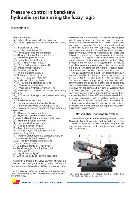
Fig. 1. Band-<strong>saw</strong> mach<strong>in</strong>e: 1 – head, 2 – <strong>band</strong>, 3 – <strong>control</strong> desk,<br />
4 – <strong>hydraulic</strong> cyl<strong>in</strong>der, 5 – electric motor<br />
ROK WYD. LXVIII ZESZYT 5/2009 35
Model of <strong>the</strong> mechanical <strong>system</strong><br />
Schematic diagram of mechanical part of <strong>the</strong> <strong>system</strong><br />
is shown <strong>in</strong> fig. 2.<br />
Differential equation of rotation of <strong>the</strong> head can be<br />
formulated as follows:<br />
In <strong>the</strong> model <strong>the</strong> follow<strong>in</strong>g moments were taken<br />
<strong>in</strong>to consideration: of spr<strong>in</strong>g force, of gravity, of <strong>hydraulic</strong><br />
cyl<strong>in</strong>der and of cutt<strong>in</strong>g forces. Length of spr<strong>in</strong>g<br />
Fig. 2. Diagram of <strong>the</strong> <strong>band</strong>-<strong>saw</strong>: a) frame of <strong>the</strong> head, b) spr<strong>in</strong>g,<br />
c) <strong>hydraulic</strong> cyl<strong>in</strong>der, d) cutt<strong>in</strong>g <strong>band</strong><br />
and arm of spr<strong>in</strong>g force depends on <strong>the</strong> angle of head<br />
rotation. Therefore, moment of <strong>the</strong> spr<strong>in</strong>g force can<br />
be calculated as:<br />
where distances between po<strong>in</strong>ts 2 and 3 (fig. 2) were<br />
calculated from geometrical dependencies. Formula<br />
Fig. 3. Model of <strong>the</strong> <strong>system</strong> <strong>in</strong> Simul<strong>in</strong>k<br />
36<br />
(1)<br />
(2)<br />
of moment of <strong>hydraulic</strong> cyl<strong>in</strong>der force allows for<br />
change <strong>hydraulic</strong> cyl<strong>in</strong>der length and arm of <strong>the</strong> force:<br />
ROK WYD. LXVIII ZESZYT 5/2009<br />
(3)<br />
Moment of gravity force was calculated as follows:<br />
In <strong>the</strong> model two components of cutt<strong>in</strong>g force were<br />
taken <strong>in</strong>to consideration: normal to direction of <strong>the</strong><br />
<strong>band</strong> movement P y and tangent P z . It was assumed<br />
that force P y is a result of <strong>band</strong> deflection. Deflection<br />
is caused by difference between angular velocity<br />
of <strong>the</strong> head and vertical feed of <strong>the</strong> <strong>band</strong>. The value<br />
of this force was used to calculate two fur<strong>the</strong>r parameters.<br />
The first one was moment, assum<strong>in</strong>g that<br />
<strong>the</strong> arm is 0,405 m:<br />
The second parameter was current thickness of<br />
material cut by one tooth (vertical feed of <strong>the</strong> <strong>band</strong><br />
p vf ), accord<strong>in</strong>g to Wojnarowski J. [1]<br />
On <strong>the</strong> basis of p vf value tangent force was computed<br />
P z (Wojnarowski J. and o<strong>the</strong>rs [2], Wojnarowski<br />
J., Lisowski E., Filo G. [3]):<br />
Moment of this force was computed assum<strong>in</strong>g that<br />
<strong>the</strong> arm is 0,05 m:<br />
(4)<br />
(5)<br />
(6)<br />
(7)<br />
(8)
Model of <strong>the</strong> <strong>system</strong> was implemented as block diagram<br />
<strong>in</strong> Matlab-Simul<strong>in</strong>k <strong>system</strong>. The diagram is presented<br />
<strong>in</strong> fig. 3.<br />
Differential equation of head rotation is implemented<br />
<strong>in</strong> sub<strong>system</strong> Band-<strong>saw</strong>_head. Sub<strong>system</strong>s<br />
designed for comput<strong>in</strong>g moments act<strong>in</strong>g on <strong>the</strong><br />
head are as follows: Mom_spr<strong>in</strong>g, Mom_gravity,<br />
Mom_cyl<strong>in</strong>der, Mom_Pz1, Mom_Py. Output signals<br />
of <strong>the</strong>se sub<strong>system</strong>s are summed and used as <strong>in</strong>put<br />
for Band-<strong>saw</strong>_head sub<strong>system</strong>. These signals are<br />
also written <strong>in</strong>to variables M_spr<strong>in</strong>g, M_gravity,<br />
M_cyl<strong>in</strong>der, M_Pz1 and M_Py1 for creat<strong>in</strong>g time<br />
courses. Angle of rotation of head is used for comput<strong>in</strong>g<br />
number of teeth currently used <strong>in</strong> cutt<strong>in</strong>g<br />
process for various shapes of material <strong>in</strong> sub<strong>system</strong><br />
Teeth_number. Block Control_<strong>system</strong> consists of<br />
models of regulators with algorithms: PID and Fuzzy<br />
Logic. There is also a possibility of carry<strong>in</strong>g out<br />
simulations without any regulator. In sub<strong>system</strong><br />
PLOTS are collected all time courses of parameters<br />
created us<strong>in</strong>g blocks Scope.<br />
Model of <strong>the</strong> <strong>hydraulic</strong> <strong>system</strong><br />
The pressure force was <strong>control</strong>led by a <strong>hydraulic</strong><br />
<strong>system</strong> which consists of proportional relief valve.<br />
The <strong>system</strong> is shown <strong>in</strong> fig. 4. This <strong>system</strong> allows for<br />
obta<strong>in</strong><strong>in</strong>g <strong>the</strong> proper run of force hold<strong>in</strong>g down head<br />
to cut material. It was realized by <strong>control</strong>l<strong>in</strong>g pressure<br />
<strong>in</strong> l<strong>in</strong>e between supply unit and <strong>hydraulic</strong> cyl<strong>in</strong>der.<br />
Fig. 4. Scheme of <strong>the</strong> <strong>hydraulic</strong> <strong>system</strong>: 1 – supply unit, 2 – <strong>control</strong><br />
valve, 3 – <strong>hydraulic</strong> cyl<strong>in</strong>der, 4 – proportional relief valve,<br />
5 – <strong>control</strong>ler<br />
The <strong>hydraulic</strong> <strong>system</strong> consists of supply unit 1, <strong>control</strong><br />
valve 2, <strong>hydraulic</strong> cyl<strong>in</strong>der rod 3, proportional<br />
relief valve 4 and <strong>control</strong> unit 5. The <strong>control</strong>ler generates<br />
<strong>control</strong> signal for <strong>the</strong> valve on <strong>the</strong> basis of signal<br />
from transducer <strong>in</strong>stalled on cutt<strong>in</strong>g head. Flow<br />
Fig. 5. Block diagram of sub<strong>system</strong> Control_<strong>system</strong><br />
balance of <strong>hydraulic</strong> cyl<strong>in</strong>der chamber was formulated<br />
with assumed bulk modulus of work<strong>in</strong>g fluid:<br />
In <strong>the</strong> <strong>hydraulic</strong> <strong>system</strong> a pilot operat<strong>in</strong>g proportional<br />
relief valve with two movable elements is used:<br />
a pilot at first stage and a piston at second stage.<br />
Equation of <strong>the</strong> piston motion is as it follows:<br />
ROK WYD. LXVIII ZESZYT 5/2009 37<br />
(9)<br />
(10)<br />
while equation of pilot motion can be formulated as:<br />
(11)<br />
The electromagnetic force F el act<strong>in</strong>g on valve pilot<br />
is proportional to <strong>control</strong> signal U: F el = k · U.<br />
The ma<strong>in</strong> flow rate through <strong>the</strong> piston gap can be<br />
described by formula:<br />
(12)<br />
where width of piston gap A sz can be computed on <strong>the</strong><br />
basis of valve geometry.<br />
Controller design<br />
Models of regulators were implemented <strong>in</strong> model of<br />
ma<strong>in</strong> <strong>system</strong> (fig. 3) <strong>in</strong> sub<strong>system</strong> Control_<strong>system</strong>.<br />
Block diagram of this sub<strong>system</strong> is shown <strong>in</strong> fig. 5.<br />
As it arises from fig. 5, <strong>control</strong>ler <strong>in</strong>put signal is<br />
current value of force act<strong>in</strong>g on s<strong>in</strong>gle cutt<strong>in</strong>g tooth<br />
Fig. 6. Control surface of FLC <strong>control</strong>ler
Fig. 7. Block diagram of sub<strong>system</strong> for comput<strong>in</strong>g number of cutt<strong>in</strong>g teeth<br />
Py1. This parameter is time-quantized with zero order<br />
hold (Brzózka J. [4], Frankl<strong>in</strong> G. F. [5]) with assumed<br />
sampl<strong>in</strong>g frequency. Then is computed and normalized<br />
<strong>control</strong> error value e. The normalized <strong>control</strong><br />
error is an <strong>in</strong>put value for <strong>control</strong>lers <strong>in</strong> blocks:<br />
Fuzzy_Controller and PID_Controller. It is also used for<br />
comput<strong>in</strong>g value of ISE parameter which determ<strong>in</strong>es<br />
<strong>control</strong> quality. Sub<strong>system</strong> proximity_detector is used<br />
for decreas<strong>in</strong>g speed of head while approach<strong>in</strong>g to<br />
material, which prevents from impact load.<br />
Model of Fuzzy Logic Controller (FLC) was built<br />
us<strong>in</strong>g Fuzzy Logic Toolbox, which is one of tools<br />
available <strong>in</strong> Matlab <strong>system</strong>. FLC has two <strong>in</strong>put signals<br />
38<br />
and one output signal, which are analogous with<br />
<strong>in</strong>cremental PI <strong>control</strong>ler Driankow D., Hellendoorn H.,<br />
Ra<strong>in</strong>frank M. [6], Piegat A. [7]. After adjust<strong>in</strong>g parameters,<br />
<strong>control</strong> surface was obta<strong>in</strong>ed as shown <strong>in</strong><br />
fig. 6. The figure shows dependency between <strong>in</strong>put<br />
signals: e (value of <strong>control</strong> error) and ∆e (change of<br />
<strong>control</strong> error from last step) and output: change of<br />
<strong>control</strong> signal ∆U.<br />
Simulation<br />
Simulations of cutt<strong>in</strong>g process were carried out<br />
with several different shapes of cross-sections. In<br />
Fig. 8. Time courses of tooth force at <strong>the</strong> beg<strong>in</strong>n<strong>in</strong>g of cutt<strong>in</strong>g<br />
process: a) without <strong>control</strong>ler, b) with PID <strong>control</strong>ler, c) with<br />
<strong>fuzzy</strong> <strong>control</strong>ler<br />
each simulation <strong>control</strong>ler ma<strong>in</strong>ta<strong>in</strong>ed an optimal<br />
value of tooth force, <strong>in</strong>dependently from angle of<br />
head and shape of material. Ma<strong>in</strong> results of simulations<br />
were time courses of parameters like: rotation<br />
angle of head, tooth force, number of cutt<strong>in</strong>g teeth,<br />
<strong>control</strong> signal, moments etc.<br />
Models of cut shapes<br />
Comput<strong>in</strong>g number of cutt<strong>in</strong>g teeth was carried out<br />
<strong>in</strong> sub<strong>system</strong> Teeth_number. Block diagram of this<br />
sub<strong>system</strong> is shown <strong>in</strong> fig. 7. The <strong>in</strong>put signal <strong>in</strong> this<br />
sub<strong>system</strong> is current rotation angle of <strong>the</strong> cutt<strong>in</strong>g<br />
head. Three example cross-sections: triangular, circu-<br />
ROK WYD. LXVIII ZESZYT 5/2009
Fig. 9. Time courses of tooth force while obta<strong>in</strong><strong>in</strong>g stabilized<br />
value of tooth force: a) without <strong>control</strong>ler, b) with PID <strong>control</strong>ler,<br />
c) with <strong>fuzzy</strong> <strong>control</strong>ler<br />
lar and tubular are implemented <strong>in</strong> <strong>the</strong> model. Three<br />
blocks: Triangular, Round and Tubular allow for comput<strong>in</strong>g<br />
number of cutt<strong>in</strong>g teeth for each shape. Shape<br />
can be chosen us<strong>in</strong>g manual switches Sw1 and Sw2.<br />
Block Vibrations allows for add<strong>in</strong>g step change of<br />
teeth force which appears when tooth enters and material<br />
exits. The output signal is written <strong>in</strong>to variable<br />
Profil for us<strong>in</strong>g <strong>in</strong> o<strong>the</strong>r part of <strong>the</strong> model.<br />
Simulations of cutt<strong>in</strong>g tubular profile<br />
As an example results of simulation obta<strong>in</strong>ed with<br />
tubular profile are presented. This is one of more<br />
difficult cases, because while cutt<strong>in</strong>g this type of profile<br />
<strong>the</strong>re are rapid changes of number of cutt<strong>in</strong>g teeth.<br />
Outer radius of profile was assumed as r = 30 mm,<br />
Fig. 10. Time courses of tooth force at <strong>the</strong> end of cutt<strong>in</strong>g process:<br />
a) without <strong>control</strong>ler, b) with PID <strong>control</strong>ler, c) with <strong>fuzzy</strong><br />
<strong>control</strong>ler<br />
ROK WYD. LXVIII ZESZYT 5/2009 39
wall thickness g = 5 mm. Time courses of tooth force<br />
while cutt<strong>in</strong>g tubular profile with various <strong>control</strong><br />
methods are presented <strong>in</strong> fig. 8 – 10. The optimal<br />
value of tooth force was assumed as F yp_opt = 60 N.<br />
The time courses of angle and rotational speed<br />
of <strong>the</strong> head while cutt<strong>in</strong>g tubular profile are presented<br />
<strong>in</strong> fig. 11.<br />
As it arises from fig. 8 – 11, application of FLC <strong>control</strong>ler<br />
reduces changes of tooth force amplitude at <strong>the</strong><br />
beg<strong>in</strong>n<strong>in</strong>g and at <strong>the</strong> end of <strong>the</strong> process (fig. 8 – 10).<br />
Cutt<strong>in</strong>g without <strong>control</strong>ler (fig. 8a) causes strong impact<br />
with tooth force over 200 N when cutt<strong>in</strong>g <strong>band</strong><br />
first time touches profile. An application of PID <strong>control</strong>ler<br />
(fig. 8b) reduces maximum impact to 160 N, and<br />
an application of FLC (fig. 8c) reduces it to 140 N.<br />
While us<strong>in</strong>g PID <strong>control</strong>ler stabilized value of tooth<br />
force 60 N is obta<strong>in</strong>ed after 3.0 seconds, with FLC<br />
– after 2.8 seconds (fig. 9b, 9c). The cutt<strong>in</strong>g time is<br />
reduced from 18 seconds without <strong>control</strong>ler (fig. 10a)<br />
to 14 seconds with FLC (fig. 10c).<br />
40<br />
Conclusion<br />
Solution proposed <strong>in</strong> this work consists <strong>in</strong> upgrad<strong>in</strong>g<br />
of tooth force <strong>control</strong> <strong>system</strong> <strong>in</strong> <strong>band</strong>-<strong>saw</strong><br />
mach<strong>in</strong>e us<strong>in</strong>g <strong>the</strong> PID <strong>control</strong>ler and <strong>the</strong> FLC <strong>control</strong>ler.<br />
Applied <strong>control</strong>lers allow for ma<strong>in</strong>ta<strong>in</strong><strong>in</strong>g value<br />
of tooth force dur<strong>in</strong>g <strong>the</strong> cutt<strong>in</strong>g process at <strong>the</strong> level<br />
close to optimal. Value of this force is <strong>in</strong>dependent<br />
from rotation angle of cutt<strong>in</strong>g head, shape and size of<br />
material profile. Us<strong>in</strong>g such <strong>control</strong>lers shortens cutt<strong>in</strong>g<br />
time and causes less wear of teeth.<br />
Proposed <strong>control</strong> <strong>system</strong> can be applied to exist<strong>in</strong>g<br />
<strong>hydraulic</strong> <strong>system</strong> of <strong>band</strong>-<strong>saw</strong> mach<strong>in</strong>es. It requires<br />
only small changes <strong>in</strong> a <strong>hydraulic</strong> <strong>system</strong>. The ma<strong>in</strong><br />
change is us<strong>in</strong>g electromagnetically <strong>control</strong>led proportional<br />
relief valve <strong>in</strong> exchange for manually <strong>control</strong>led<br />
throttle valve. Digital modules of <strong>control</strong>lers<br />
and transducers for measur<strong>in</strong>g rotation angle of<br />
cutt<strong>in</strong>g head and pressure <strong>in</strong> <strong>hydraulic</strong> cyl<strong>in</strong>der or<br />
pressure force act<strong>in</strong>g on cut material must be also<br />
added.<br />
Simulations were carried out with two types of <strong>control</strong>lers:<br />
PID and FLC. It arises from <strong>the</strong> results, that<br />
application of both types of <strong>control</strong>lers allowed for<br />
obta<strong>in</strong><strong>in</strong>g similar effects. Cutt<strong>in</strong>g time was 2 – 10%<br />
Fig. 11. Time courses obta<strong>in</strong>ed while cutt<strong>in</strong>g tubular profile with FLC: 1 – angle of cutt<strong>in</strong>g head (α), 2 – rotational speed of cutt<strong>in</strong>g<br />
head (ω)<br />
shorter while us<strong>in</strong>g FLC <strong>control</strong>ler, while ISE <strong>in</strong>dex<br />
was 1 – 8% lower with PID <strong>control</strong>ler. Application of<br />
FLC <strong>control</strong>ler reduced better oscillations at <strong>the</strong> beg<strong>in</strong>n<strong>in</strong>g<br />
of cutt<strong>in</strong>g process when <strong>the</strong> <strong>band</strong> first time contacts<br />
material. There are also greater possibilities of<br />
adjust<strong>in</strong>g <strong>control</strong>ler parameters when us<strong>in</strong>g FLC. In<br />
this case <strong>the</strong> number of <strong>fuzzy</strong> sets can be easily <strong>in</strong>creased<br />
and more <strong>in</strong>put signals can be added, for<br />
example rotation angle of cutt<strong>in</strong>g head or <strong>band</strong>-<strong>saw</strong><br />
driv<strong>in</strong>g moment. Fur<strong>the</strong>r extension of FLC and additional<br />
tests can lead to obta<strong>in</strong> even better results.<br />
REFERENCES<br />
1. Wojnarowski J.: Model komputerowy przec<strong>in</strong>arek z pi∏ami<br />
taÊmowymi bez koƒca w badaniu zjawisk dynamicznych<br />
w procesie ci´cia. Silesian University of Technology, Gliwice<br />
2002.<br />
2. Wojnarowski J. and o<strong>the</strong>rs: Ograniczanie drgaƒ przec<strong>in</strong>arek<br />
z taÊmowymi pi∏ami bez koƒca. Monograph, Silesian University<br />
of Technology, Gliwice 2007.<br />
3. Wojnarowski J., Lisowski E., Filo G.: Sterowanie <strong>hydraulic</strong>znym<br />
uk∏adem nacisku pi∏y bez koƒca przy zastosowaniu<br />
regulatora FLC. XX Konferencja Naukowa Problemy Rozwoju<br />
Maszyn Roboczych, Zakopane 2007.<br />
4. Brzózka J.: Regulatory cyfrowe w automatyce. MIKOM, Warszawa<br />
2002.<br />
5. Frankl<strong>in</strong> G. F.: Digital <strong>control</strong> of dynamic <strong>system</strong>s. Addison<br />
Wesley Longman Inc, Menlo Park CA 1998.<br />
6. Driankow D., Hellendoorn H., Ra<strong>in</strong>frank M.: An Introduction<br />
to Fuzzy Control. Spr<strong>in</strong>ger-Verlag, Berl<strong>in</strong> 1993.<br />
7. Piegat A.: Modelowanie i sterowanie rozmyte. Akad. Oficyna<br />
Wydawn. EXIT Warszawa 1999.<br />
ROK WYD. LXVIII ZESZYT 5/2009