Concept of active counterweight system for medium excavator
Concept of active counterweight system for medium excavator
Concept of active counterweight system for medium excavator

You also want an ePaper? Increase the reach of your titles
YUMPU automatically turns print PDFs into web optimized ePapers that Google loves.
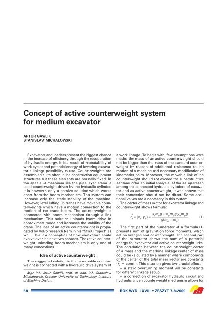
<strong>Concept</strong> <strong>of</strong> <strong>active</strong> <strong>counterweight</strong> <strong>system</strong><br />
<strong>for</strong> <strong>medium</strong> <strong>excavator</strong><br />
ARTUR GAWLIK<br />
STANIS¸AW MICHA¸OWSKI<br />
Excavators and loaders present the biggest chance<br />
in the increase <strong>of</strong> efficiency through the recuperation<br />
<strong>of</strong> hydraulic energy. It is a result <strong>of</strong> repeatability <strong>of</strong><br />
work cycles and potential energy <strong>of</strong> lowering <strong>excavator</strong>’s<br />
linkage possibility to use. Counterweights are<br />
assembled quite <strong>of</strong>ten in the construction equipment<br />
structures but these elements are normally fixed. In<br />
the specialist machines like the pipe layer crane is<br />
used <strong>counterweight</strong> driven by the hydraulic cylinder.<br />
It is however, only a passive solution which works<br />
apart from the boom mechanism. This <strong>system</strong> can<br />
increase only the static stability <strong>of</strong> the machine.<br />
However, level luffing jib cranes have movable <strong>counterweight</strong>s<br />
which have a motion connection to the<br />
motion <strong>of</strong> the crane boom. The <strong>counterweight</strong> is<br />
connected with boom mechanism through a link<br />
mechanism. This solution unloads boom drive in<br />
approximate mode and increases the stability <strong>of</strong> the<br />
crane. The idea <strong>of</strong> an <strong>active</strong> <strong>counterweight</strong> is propagated<br />
by Volvo research team in his “SfinX Project” as<br />
well. This is a conception <strong>of</strong> how <strong>excavator</strong>s could<br />
evolve over the next two decades. The <strong>active</strong> <strong>counterweight</strong><br />
unloading boom mechanism is only one <strong>of</strong><br />
many conceptions.<br />
Idea <strong>of</strong> <strong>active</strong> <strong>counterweight</strong><br />
The suggested solution is that a movable <strong>counterweight</strong><br />
is connected with a hydraulic drive <strong>system</strong> <strong>of</strong><br />
Mgr in˝. Artur Gawlik, pr<strong>of</strong>. dr hab. in˝. Stanis∏aw<br />
Micha∏owski, Cracow University <strong>of</strong> Technology Institute<br />
<strong>of</strong> Machine Design.<br />
58<br />
a work linkage. To begin with, few assumptions were<br />
made: the mass <strong>of</strong> an <strong>active</strong> <strong>counterweight</strong> should<br />
not be bigger than the mass <strong>of</strong> the standard <strong>counterweight</strong><br />
by reason <strong>of</strong> additional resistance to the<br />
motion <strong>of</strong> a machine and necessary modification <strong>of</strong><br />
kinematics pairs. Moreover, the movable link <strong>of</strong> the<br />
<strong>counterweight</strong> should not exceed the superstructure<br />
contour. After an initial analysis, <strong>of</strong> the co-operation<br />
among the connected hydraulic cylinders <strong>of</strong> <strong>excavator</strong><br />
and an <strong>active</strong> <strong>counterweight</strong>, it was shown that<br />
their connection should not be direct. Some additional<br />
valves are a necessary in this <strong>system</strong>.<br />
The center <strong>of</strong> mass vector <strong>for</strong> <strong>excavator</strong> linkage and<br />
<strong>counterweight</strong> shows <strong>for</strong>mula:<br />
The first part <strong>of</strong> the numerator <strong>of</strong> a <strong>for</strong>mula (1)<br />
presents sum <strong>of</strong> gravitation <strong>for</strong>ce moments, which<br />
act on linkages and <strong>counterweight</strong>. The second part<br />
<strong>of</strong> the numerator shows the sum <strong>of</strong> a potential<br />
energy <strong>for</strong> <strong>excavator</strong> and <strong>active</strong> <strong>counterweight</strong> links.<br />
The correlation between the <strong>counterweight</strong> center<br />
<strong>of</strong> a mass and the machine linkage center <strong>of</strong> mass<br />
could be calculated by a manner where components<br />
<strong>of</strong> the center <strong>of</strong> the total mass vector are constants<br />
( = const.). This situation gives two crucial effects:<br />
– a static overturning moment will be constants<br />
<strong>for</strong> different linkage set up,<br />
– a connection <strong>of</strong> <strong>excavator</strong> hydraulic circuit and<br />
hydraulic driven <strong>counterweight</strong> mechanism allows <strong>for</strong><br />
ROK WYD. LXVIII ZESZYT 7-8/2009<br />
(1)
Fig. 1. Homothetic trans<strong>for</strong>mation <strong>of</strong><br />
<strong>excavator</strong> and <strong>active</strong> <strong>counterweight</strong><br />
<strong>system</strong> <strong>for</strong> scale factor k = 0,5<br />
energy flow between described<br />
<strong>system</strong>s and produces mutual<br />
static unloading from links load.<br />
Vector <strong>of</strong> center <strong>of</strong> mass position<br />
in point P <strong>for</strong> movable <strong>counterweight</strong><br />
describes equation (2):<br />
Taking into consideration that<br />
= const., result from equation<br />
(1) that point P <strong>of</strong> center <strong>of</strong> mass<br />
<strong>for</strong> <strong>active</strong> <strong>counterweight</strong> trajectory should be<br />
homothetic to point O <strong>of</strong> center <strong>of</strong> mass <strong>for</strong> <strong>excavator</strong><br />
–k<br />
linkage trajectory. Homothetic trans<strong>for</strong>mation J has s<br />
center in point S and scale factor –k (Fig. 1). It is<br />
possible to achieve it only if the <strong>counterweight</strong><br />
mechanism is homothetic to the linkage mechanism.<br />
Simplified <strong>active</strong> <strong>counterweight</strong> mechanism in relation<br />
to typical linkage is presented in Fig. 2. First<br />
link, which is connected to <strong>excavator</strong> frame, is a result<br />
<strong>of</strong> homothetic to boom. The second link represents<br />
a bucket and an arm.<br />
As far as the <strong>excavator</strong> kinematics is concerned, the<br />
biggest energy saving effect has a <strong>system</strong> with boom<br />
cylinder which is connected to the main cylinder <strong>of</strong><br />
the <strong>counterweight</strong>. A static moment round the pin <strong>of</strong><br />
the boom and the pin <strong>of</strong> the first link <strong>of</strong> <strong>counterweight</strong><br />
allows calculated equation F o = k · F p . The connected<br />
hydraulic <strong>system</strong> should ensure velocity <strong>for</strong> <strong>counterweight</strong><br />
cylinder as the <strong>for</strong>mula shows v p = k · v o . The<br />
same goes <strong>for</strong> areas <strong>of</strong> cylinders A 1 = k · A 4 .<br />
In Fig. 3 the concept <strong>of</strong> hydraulic <strong>system</strong>s <strong>for</strong> connection<br />
<strong>excavator</strong> and <strong>active</strong> <strong>counterweight</strong> mechanisms<br />
is shown. It is the main part <strong>of</strong> the <strong>system</strong>. The<br />
similar scheme could be prepared <strong>for</strong> an arm and<br />
a second link <strong>of</strong> the <strong>counterweight</strong> cylinder.<br />
Conclusion<br />
The efficiency <strong>of</strong> an <strong>active</strong> <strong>counterweight</strong> <strong>system</strong><br />
requires a simulation verification and pro<strong>of</strong> test during<br />
the stand research. Presented hydraulic <strong>system</strong> does<br />
not change the functional properties <strong>of</strong> the <strong>excavator</strong><br />
and allows the operator to shut down the movable<br />
<strong>counterweight</strong> <strong>system</strong> when it is necessary (<strong>for</strong><br />
(2)<br />
Fig. 2. Structure <strong>of</strong> <strong>excavator</strong> with <strong>active</strong> <strong>counterweight</strong><br />
example while working as a lift). Taking into consideration<br />
the assumption about the movable <strong>counterweight</strong><br />
– the scale factor <strong>of</strong> homothetic trans<strong>for</strong>mation<br />
was determined k = 0,5. Value <strong>of</strong> this factor limits the<br />
group <strong>of</strong> machines in which an <strong>active</strong> <strong>counterweight</strong><br />
<strong>system</strong> could be applied to <strong>medium</strong> size <strong>excavator</strong>s.<br />
Fig. 3. <strong>Concept</strong> <strong>of</strong> main part hydraulic <strong>system</strong> with <strong>active</strong><br />
<strong>counterweight</strong>: 1 – boom cylinder, 2 – distribution valve 3/4,<br />
3 – relief valve, 4 – filter, 5 – pump, 6 – valve 2/2, 7 – main<br />
<strong>counterweight</strong> cylinder, 8 – hydro-pneumatic accumulator<br />
ROK WYD. LXVIII ZESZYT 7-8/2009 59
List <strong>of</strong> notations<br />
A 1 , A 2 , A 3 , A 4 – Area <strong>of</strong> piston and head side <strong>of</strong> each<br />
cylinder, m 2<br />
F o , F p – Boom and <strong>counterweight</strong> cylinder <strong>for</strong>ce, N<br />
K – Scale <strong>of</strong> homothetic trans<strong>for</strong>mation (k = m o /m P )<br />
m o , m P – Total mass <strong>of</strong> <strong>excavator</strong> linkage and <strong>counterweight</strong><br />
linkage, kg<br />
v o , v p – Linear velocity <strong>of</strong> boom and <strong>counterweight</strong><br />
cylinder, m/s<br />
x o , y o – Center <strong>of</strong> mass <strong>excavator</strong> linkage coordinates<br />
in point O, m<br />
x p , y p – Center <strong>of</strong> mass <strong>counterweight</strong> linkage coordinates<br />
in point P, m<br />
60<br />
REFERENCES<br />
1. Liang X., Virvalo T.: Energy reutilization and balance analysis<br />
in a hydraulic crane. IHA, Tampere University <strong>of</strong> Technology,<br />
2003.<br />
2. Cetinkunt S., Pinsopon U., Chen C., Egelja A., Anwar S.:<br />
Positive flow control <strong>of</strong> closed-centerelectrohydraulic implement-by-wire<br />
<strong>system</strong>s <strong>for</strong> mobile equipment applications.<br />
Mechatronics 14/2004, pp. 403 – 420.<br />
3. Qing X., Qingfeng W., Yanting Z.: Control strategies <strong>of</strong><br />
power <strong>system</strong> in hybrid hydraulic <strong>excavator</strong>. Automation in<br />
Construction 17/2008, pp. 361 – 367.<br />
4. Sobczyk A., Buczak G.: Hydraulic-mechanical energy saving<br />
<strong>system</strong> in cranes and tranportation equipment. Proc. Of<br />
4-th FPNI-PhD Symposium, Sarasota 2006, pp. 641 – 648.<br />
ROK WYD. LXVIII ZESZYT 7-8/2009