Magnetoelectric coupling in multiferroic Ba(Fe0.01Ti0.99)O3 ...
Magnetoelectric coupling in multiferroic Ba(Fe0.01Ti0.99)O3 ...
Magnetoelectric coupling in multiferroic Ba(Fe0.01Ti0.99)O3 ...

Create successful ePaper yourself
Turn your PDF publications into a flip-book with our unique Google optimized e-Paper software.
<strong>Magnetoelectric</strong> <strong>coupl<strong>in</strong>g</strong> <strong>in</strong> <strong>multiferroic</strong><br />
<strong>Ba</strong>(<strong>Fe0.01Ti0.99</strong>)<strong>O3</strong> nanowires<br />
Jaspreet Kaur 1* , Jasneet Kaur 1 , Jyoti Shah 2 , R.K. Kotnala 2 , V<strong>in</strong>ay Gupta 3 , Kuldeep Chand<br />
Verma 1<br />
1 Department of Physics, Eternal University, <strong>Ba</strong>ru Sahib, Sirmour (H.P.) 173101, India<br />
2 National Physical Laboratory, New Delhi-110012, India<br />
3 Department of Physics and Astrophysics, University of Delhi, Delhi 110007, India<br />
* Correspond<strong>in</strong>g author. Tel: (+91) 9882756869; E-mail: jaspreetsonam@yahoo.co.<strong>in</strong><br />
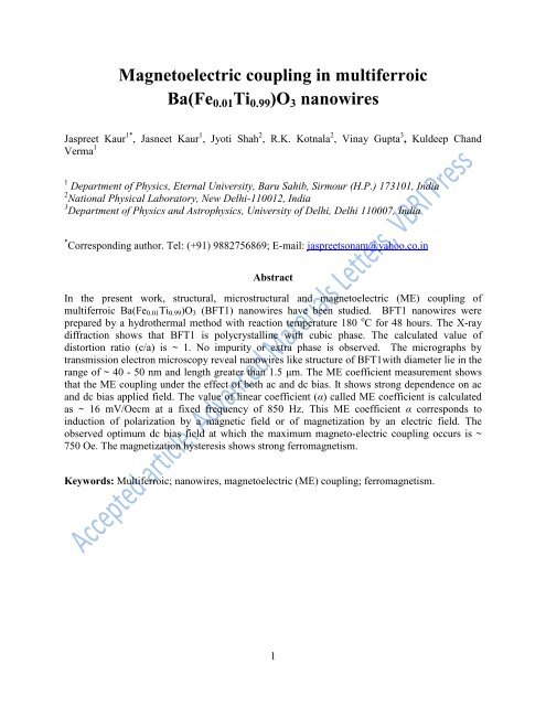
Abstract<br />
In the present work, structural, microstructural and magnetoelectric (ME) <strong>coupl<strong>in</strong>g</strong> of<br />
<strong>multiferroic</strong> <strong>Ba</strong>(<strong>Fe0.01Ti0.99</strong>)<strong>O3</strong> (BFT1) nanowires have been studied. BFT1 nanowires were<br />
prepared by a hydrothermal method with reaction temperature 180 o C for 48 hours. The X-ray<br />
diffraction shows that BFT1 is polycrystall<strong>in</strong>e with cubic phase. The calculated value of<br />
distortion ratio (c/a) is ~ 1. No impurity or extra phase is observed. The micrographs by<br />
transmission electron microscopy reveal nanowires like structure of BFT1with diameter lie <strong>in</strong> the<br />
range of ~ 40 - 50 nm and length greater than 1.5 μm. The ME coefficient measurement shows<br />
that the ME <strong>coupl<strong>in</strong>g</strong> under the effect of both ac and dc bias. It shows strong dependence on ac<br />
and dc bias applied field. The value of l<strong>in</strong>ear coefficient (α) called ME coefficient is calculated<br />
as ~ 16 mV/Oecm at a fixed frequency of 850 Hz. This ME coefficient α corresponds to<br />
<strong>in</strong>duction of polarization by a magnetic field or of magnetization by an electric field. The<br />
observed optimum dc bias field at which the maximum magneto-electric <strong>coupl<strong>in</strong>g</strong> occurs is ~<br />
750 Oe. The magnetization hysteresis shows strong ferromagnetism.<br />
Keywords: Multiferroic; nanowires, magnetoelectric (ME) <strong>coupl<strong>in</strong>g</strong>; ferromagnetism.<br />
1
Introduction<br />
Over the past decade <strong>in</strong> scientific community, one-dimensional <strong>multiferroic</strong><br />
nanostructures, like nanorods, nanowires, nanotubes, etc. have received considerable attention.<br />
They are promis<strong>in</strong>g candidates for realiz<strong>in</strong>g nanoscale electronic, optical, and mechanical<br />
devices because they reta<strong>in</strong> wire-like connectivity despite their nanoscale radial dimension [1].<br />
The synthesis of <strong>multiferroic</strong> nanostructures with controllable size and shape is essential for<br />
fundamental studies. Among various <strong>multiferroic</strong> materials, transition metal doped <strong>Ba</strong>Ti<strong>O3</strong> is the<br />
best material, possess<strong>in</strong>g a perovskite structure with Curie temperature of 132 o C [2-4]. The<br />
synthesis of transition metal doped <strong>Ba</strong>Ti<strong>O3</strong> nanostructures are of great importance and has<br />
attracted much attention due to its novel shape and size dependent properties. For <strong>in</strong>stance, the<br />
zero dimensional <strong>Ba</strong>Ti<strong>O3</strong> nanoparticles, the ferroelectric Curie temperature decreases<br />
progressively with particles size [5, 6]. On the other hand one dimensional <strong>Ba</strong>Ti<strong>O3</strong> nanowires<br />
still reta<strong>in</strong> their ferroelectric properties, and non-volatile polarization doma<strong>in</strong>s with dimensions<br />
can be <strong>in</strong>duced <strong>in</strong> the nanowires. This further open ups the possibility of fabricat<strong>in</strong>g <strong>Ba</strong>Ti<strong>O3</strong><br />
nanowire-based nonvolatile memory devices and for many more applications [7,8]. The<br />
polarization with<strong>in</strong> <strong>in</strong>dividual ferroelectric doma<strong>in</strong>s of the nanowire generally orient along the<br />
wire axis.<br />
By def<strong>in</strong>ition, a s<strong>in</strong>gle phase <strong>multiferroic</strong> is a material that simultaneously possesses two<br />
or more ferroic order parameters- ferromagnetism and ferroelectricity [9]. The important<br />
property that makes this material attractive is the magnetoelectric (ME) effect, i.e. the <strong>in</strong>duction<br />
of magnetization by an electric field or polarization by a magnetic field [10]. The preparation of<br />
such materials provide opportunities for potential applications <strong>in</strong> sp<strong>in</strong>tronics, magneto-electric<br />
sensors <strong>in</strong> optoelectronics and microwave electronics, multi-state memory devices with dual<br />
magnetic and electric controls, magnetic record<strong>in</strong>g read heads and also to encode the <strong>in</strong>formation<br />
<strong>in</strong> electric polarization and magnetization to obta<strong>in</strong> four logic states [11,12]. The ME effect can<br />
be either <strong>in</strong>tr<strong>in</strong>sic <strong>in</strong> s<strong>in</strong>gle phase materials or extr<strong>in</strong>sic, <strong>in</strong> composite materials. The M-E<br />
behavior <strong>in</strong> <strong>multiferroic</strong>s is found to be strongly dependent on the material properties such as<br />
dielectric constants, piezoelectric constants, and spatial architecture of the material characterized<br />
by the volume fractions of the phases, the shape and orientation of particles of these phases, their<br />
connectivity and mutual positions [12]. In compounds with no time-reversal and no space<br />
<strong>in</strong>version symmetries, an <strong>in</strong>tr<strong>in</strong>sic magneto-electric <strong>coupl<strong>in</strong>g</strong> occurs. In such materials, an<br />
applied electric field, E, displac<strong>in</strong>g the magnetic ions, eventually changes the exchange<br />
<strong>in</strong>teraction between them and hence the magnetic properties of the compound [13].<br />
Accord<strong>in</strong>g to Landau theory [14,15], the ME effect is described <strong>in</strong> the Gibbs-Free energy<br />
(F) of the system <strong>in</strong> the terms of an applied magnetic field H and an applied electric field E.<br />
( )<br />
where the first term on the right hand side expla<strong>in</strong>s the contribution result<strong>in</strong>g from the electrical<br />
response to an electric field, where εo is the permittivity of free space, and the relative<br />
permittivity εij(T) is a second-rank tensor which is <strong>in</strong>dependent of Ei <strong>in</strong> non-ferroic materials.<br />
The second term is the magnetic equivalent of the first term, where μij(T) is the relative<br />
permeability and μo is the permeability of free space. The third term describes l<strong>in</strong>ear<br />
magnetoelectric <strong>coupl<strong>in</strong>g</strong> via αij(T); the third-rank tensors βijk(T) and γijk(T) represent higherorder<br />
(quadratic) magnetoelectric coefficients. The magnetoelectric effects can then easily be<br />
established <strong>in</strong> the form Pi(Hj) or Mi(Ej). The former is obta<strong>in</strong>ed by differentiat<strong>in</strong>g F with respect<br />
2<br />
(1)
to Ei, and then sett<strong>in</strong>g Ei = 0. A complementary operation <strong>in</strong>volv<strong>in</strong>g Hi establishes the latter. One<br />
obta<strong>in</strong>s:<br />
and<br />
The l<strong>in</strong>ear ME <strong>coupl<strong>in</strong>g</strong> coefficient (α) can be <strong>in</strong>troduced either electrically (αE = dM/dH) or<br />
magnetically (αH = dP/dH = εoεr dE/dH).<br />
Landau and Lifshitz were the first to observe the ME effect <strong>in</strong> 1957 and later it was<br />
confirmed <strong>in</strong> an antiferromagnetic s<strong>in</strong>gle crystal Cr2<strong>O3</strong>. Subsequently, observations of ME effect<br />
<strong>in</strong> many other <strong>multiferroic</strong> crystals have been reported. However, ME effect <strong>in</strong> these materials is<br />
usually small and for the materials to be technologically viable, large ME <strong>coupl<strong>in</strong>g</strong> must be<br />
demonstrated. So, much attention is given <strong>in</strong> develop<strong>in</strong>g <strong>multiferroic</strong>s possess<strong>in</strong>g higher ME<br />
<strong>coupl<strong>in</strong>g</strong> coefficients. For potential application of such materials, theoretical studies on the ME<br />
<strong>coupl<strong>in</strong>g</strong> are very important. Various researchers have worked on different aspects of ME effect<br />
<strong>in</strong> nanomaterials. Liu et al. [16] studied the static ME <strong>coupl<strong>in</strong>g</strong> us<strong>in</strong>g Landau’s theory with the<br />
consideration of residual stra<strong>in</strong>s. Nan et al.[17] used green’s function method comb<strong>in</strong>ed with<br />
perturbation theory to study the composite of <strong>Ba</strong>Ti<strong>O3</strong> and CoFe2O4. Duan et al. [18] reported<br />
that the atomic displacement at Fe/<strong>Ba</strong>Ti<strong>O3</strong>(001) <strong>in</strong>terface caused by ferroelectric switch<strong>in</strong>g<br />
change the overlap between atomic orbital at the <strong>in</strong>terface that affects the magnetization at the<br />
<strong>in</strong>terface. Despite all these, we need to focus on the size, shape and surface effects on the<br />
stability of ME <strong>coupl<strong>in</strong>g</strong> for nanoscale materials.<br />
In order to realize the potential application of 1-D <strong>Ba</strong>Ti<strong>O3</strong> nanostructures, it is necessary<br />
to develop synthetic methods to fabricate these nanostructures. Several methods such as sol-gel,<br />
templat<strong>in</strong>g methods, hydrothermal method, etc. are reported for the fabrication of <strong>Ba</strong>Ti<strong>O3</strong>.<br />
Among them, hydrothermal method has been referred as a versatile, low cost and<br />
environmentally friendly method for preparation of <strong>Ba</strong>Ti<strong>O3</strong> nanostructures. Here <strong>in</strong>, we report<br />
the hydrothermal fabrication of <strong>Ba</strong>(<strong>Fe0.01Ti0.99</strong>)<strong>O3</strong> (BFT1) nanowires and present their structural,<br />
microstructural, ferromagnetic and magneto-electric <strong>coupl<strong>in</strong>g</strong> effect.<br />
Experimental<br />
BFT1 nanowires were fabricated via hydrothermal process, and the typical synthesized<br />
process is described as the follow<strong>in</strong>g. The chemicals used for the preparation of BFT1 precursor<br />
were barium acetate (Loba Chemie, 98% purity), tetra-n-butyl orthotitanate (Merck, 98%), ferric<br />
chloride (Merck, 96%), ethanol (Merck, 99.9%) and NaOH (Nice, 98%). Initially 0.01M of high<br />
purity tetra-n-butyl-orthotitanate was dissolved <strong>in</strong> ethanol to form a uniform solution by stirr<strong>in</strong>g<br />
and also 0.01M of barium acetate was dissolved <strong>in</strong> de-ionized water uniformly. Subsequently,<br />
the previous solution was slowly <strong>in</strong>troduced <strong>in</strong>to the later solution along with 1% dop<strong>in</strong>g of<br />
ferric chloride. The pH value of the mixed solution was adjusted to 13.0 by add<strong>in</strong>g NaOH. The<br />
mixture was then transferred to an auto clave (filled up to about 80% capacity) where it was<br />
immediately sealed and placed <strong>in</strong> the furnace. The hydrothermal reaction for BFT1 was carried<br />
out at 180 o C for 48 hours. After cool<strong>in</strong>g down at room temperature, BFT1 solution was filtered<br />
and washed with distilled water and ethanol for several times to remove the absorbed impurities,<br />
3<br />
(2)<br />
(3)
and f<strong>in</strong>ally dried at 80 o C <strong>in</strong> an oven for 8 hours. The crystal structure was <strong>in</strong>vestigated by X-ray<br />
diffraction (XRD) us<strong>in</strong>g X’Pert PRO PAN alytical system. Microstructure was determ<strong>in</strong>ed by<br />
transmission electron microscopy (TEM) us<strong>in</strong>g TECNAI G 2 T30, U-TWIN. Magnetization<br />
measurements were performed us<strong>in</strong>g vibrat<strong>in</strong>g sample magnetometer (VSM-735). The Magneto<br />
electric (ME) effect of was performed by us<strong>in</strong>g Dynamic <strong>Magnetoelectric</strong> <strong>coupl<strong>in</strong>g</strong> measurement<br />
Setup.<br />
Fig. 1. XRD pattern of BFT1 nanowires.<br />
Results and Discussion<br />
The purity and crystall<strong>in</strong>ity of the synthesized sample was exam<strong>in</strong>ed by the powder XRD<br />
technique. The XRD pattern of BFT1 prepared at 180 o C /48h is shown <strong>in</strong> Fig.1, exhibit<strong>in</strong>g that<br />
the product is made up of good crystallization. It is found that the present <strong>multiferroic</strong> system is<br />
polycrystall<strong>in</strong>e <strong>in</strong> nature with Pm3m space group <strong>in</strong> a cubic phase. The value of distortion ratio<br />
(c/a) is ~ 1. The diffraction pattern <strong>in</strong> the 2θ = 40°–50° region is usually characteristic of the<br />
presence of either cubic or tetragonal <strong>Ba</strong>Ti<strong>O3</strong> structure. In this case, no splitt<strong>in</strong>g of cubic (200)<br />
<strong>in</strong>to tetragonal (200) and (002) reflections at about 45° can be observed. The XRD pattern for<br />
BFT1 shows cubic symmetry with lattice constants a = 4.0336Å. The broad XRD l<strong>in</strong>es <strong>in</strong>dicate<br />
4
the products are result<strong>in</strong>g of nanosize.<br />
Figure 2 reveals the morphology and structure of BFT1. It shows that BFT1 consists of<br />
wires of diameter of the range 40-50 nm and length greater than 1μm. For BFT1 the nucleation<br />
and growth process takes place by Ostwald ripen<strong>in</strong>g process. Along with Ostwald ripen<strong>in</strong>g, it can<br />
be expected that particle growth occurs by a coalescence mechanism, i.e., oriented attachment<br />
[19]. In this process Fe 3+ ions replace the Ti 4+ ions and due to their difference <strong>in</strong> ionic radii,<br />
larger crystals with their greater volume to surface area ratio, are more energetically favored than<br />
smaller crystals and represent a lower energy state. For materials with an anisometric crystal<br />
lattice, 1D growth is more easily obta<strong>in</strong>ed due to the energy difference between different crystals<br />
faces which have different atomic density and atoms on different facets have a different number<br />
of unsatisfied bonds or broken bonds. Hence, leads to different growth mechanisms and varied<br />
growth rates. The ma<strong>in</strong> hypothesis about the role of oriented attachment <strong>in</strong> hydrothermal<br />
conditions is that under dispersed conditions, the anisotropic particles are formed by successive<br />
collisions without gra<strong>in</strong> rotation and can lead to various particle shapes. Whereas under<br />
agglomerated conditions, alignment by gra<strong>in</strong> rotation can occur if the particles are <strong>in</strong> contact.<br />
However, s<strong>in</strong>ce the crystallographic alignment can be satisfied at any po<strong>in</strong>t of the particle’s<br />
surface, the f<strong>in</strong>al particle can result from several attachment events along the same surface,<br />
giv<strong>in</strong>g an uncontrollable shape. This alternative can be effective under both agglomerated and<br />
dispersed conditions: <strong>in</strong> agglomerates, the presence of an adhered compound may lead to<br />
oriented agglomerates and, under dispersed conditions; the steric h<strong>in</strong>drance may lead to effective<br />
collisions <strong>in</strong> only one crystallographic direction. This leads to the formation of BFT1 nanowires.<br />
Fig. 2. TEM images of BFT1 nanowires.<br />
5
Fig. 3. Magnetization hysteresis (M-H) loop of BFT1 nanowires.<br />
Figure 3 shows ferromagnetism <strong>in</strong> BFT1 with a typical hysteresis loop with saturation<br />
magnetization, Ms ~ 82.23 memu/g, remnant magnetization, Mr ~31.91 memu/g and coercive<br />
field, Hc ~122.68 Oe at room temperature. The Fe 3+ ions substitut<strong>in</strong>g for Ti 4+ <strong>in</strong>troduce oxygen<br />
vacancies <strong>in</strong>to <strong>Ba</strong>Ti<strong>O3</strong>. An electron trapped <strong>in</strong> the oxygen vacancy constitutes an F-center, where<br />
electron occupies an orbital which overlaps the d-shell of both iron neighbors and these oxygen<br />
vacancies may act as a k<strong>in</strong>d of medium through which super-exchange <strong>in</strong>teractions between<br />
neighbor<strong>in</strong>g Fe 3+ ions occur. This exchange <strong>in</strong>teraction leads to ferromagnetic <strong>coupl<strong>in</strong>g</strong>.<br />
We measured the magnetically <strong>in</strong>duced ME effect, which <strong>in</strong>volves the determ<strong>in</strong>ation of<br />
the voltage on BFT1 electrodes under applied magnetic fields. Fig. 4 shows the l<strong>in</strong>ear ME effect<br />
<strong>in</strong> BFT1. The experiment <strong>in</strong>volves the measurement of the <strong>in</strong>duced voltage as a function of<br />
variable amplitude of the applied ac field at a fixed frequency of 850 Hz, which was produced by<br />
couple of Helmholtz coils. Accord<strong>in</strong>g to the theory <strong>in</strong>duced voltage should have a l<strong>in</strong>ear<br />
relationship with amplitude of the ac applied field:<br />
(<br />
⁄ ) (4)<br />
6
where V is the <strong>in</strong>duced voltage, Hac is the amplitude of the applied ac magnetic field, α is the ME<br />
<strong>coupl<strong>in</strong>g</strong> coefficient which corresponds to <strong>in</strong>duction of polarization by a magnetic field or of<br />
magnetization by an electric field and tc is the thickness of the BFT1 [20]. That confirms the<br />
theoretical l<strong>in</strong>ear relation. The calculated value of α is ~ 16 mV/Oe cm.<br />
Fig. 4. ME Voltage as a function of the<br />
amplitude of the ac field.<br />
7<br />
Fig. 5. ME Voltage as a function of the dc<br />
applied magnetic field under constant applied ac<br />
magnetic field.<br />
Figure 5 shows the <strong>in</strong>duced voltage versus dc bias field measured at fixed frequency of<br />
850 Hz of the applied ac magnetic field. The shape of the curve shows the nonl<strong>in</strong>ear behavior<br />
and the height of the peak is related to the strength of the ME <strong>coupl<strong>in</strong>g</strong>. The graph also <strong>in</strong>dicates<br />
the optimum dc bias field at which the maximum magneto-electric <strong>coupl<strong>in</strong>g</strong> occurs which is the<br />
critical parameter for the operation of <strong>multiferroic</strong> sensors and devices to maximize the energy<br />
conversion between the fields. The observed optimum dc bias field is ~ around 750 Oe.<br />
Conclusion<br />
We have synthesized BFT1 nanowires through hydrothermal method with reaction<br />
temperature 180 o C, kept for 48 hours. XRD pattern revealed the cubic structure for BFT1. TEM<br />
reveals that the average width of BFT1 nanowires is ~ 40-50 nm and length about greater than<br />
1.5 μm. The M-H hysteresis at room temperature for BFT1 shows ferromagnetism with Ms<br />
~82.23 memu/g, Mr ~31.91 memu/g and Hc~122.68 Oe. For BFT1 the magnetoelectric <strong>coupl<strong>in</strong>g</strong><br />
was observed and the calculated value of l<strong>in</strong>ear ME coefficient α ~ 16 mV/Oe cm. The observed<br />
optimum dc bias field at which the maximum magneto-electric <strong>coupl<strong>in</strong>g</strong> occurs is ~around 750<br />
Oe.
Reference<br />
1. Joshi, U.A.; Yoon, S.; <strong>Ba</strong>ik, S.; Lee, J.S. J. Phys. Chem. B 2006, 110, 12249-12256.<br />
DOI: 10.1021/jp0600110<br />
2. <strong>Ba</strong>o, N.; Shen, L.; Sr<strong>in</strong>ivasan, G.; Yanagisawa, K.; Gupta, A. J. Phys. Chem C 2008, 112,<br />
8634-8642.<br />
DOI: 10.1021/jp802055a<br />
3. Chamola, A.; S<strong>in</strong>gh, H.; Naithani, U.C. Adv. Mat. Lett. 2011, 2(2), 148.<br />
DOI: 10.5185/amlett.2010.11183<br />
4. S<strong>in</strong>gh, N.K.; Kumar, P.; Rai, R. Adv. Mat. Lett. 2011, 2(3), 200.<br />
DOI: 10.5185/amlett.2010.11178<br />
5. Pertsev, N.A.; Zembilgotov, A.G.; Tagantsev, A.K. Phys. Rev. Lett. 1998, 80, 1988.<br />
DOI: 10.1103/PhysRevLett.80.1988<br />
6. Verma, K.; sharma, S.; Sharma, D.K.; Kumar, R.; Rai, R. Adv. Mat. Lett. 2012, 3(1), 44.<br />
DOI: 10.5185/amlett.2011.5264<br />
7. Yun, W.S.; Urban, J.J.; Gu, Q.; Park, H. Nano lett. 2002, 2, 447.<br />
DOI: 10.1021/nl015702g<br />
8. Mao, Y.; <strong>Ba</strong>nerjee, S.; Wong, S.S. J. Am. Chem. Soc. 2003, 125, 15718.<br />
DOI: 10.1021/ja038192w<br />
9. Sr<strong>in</strong>ivas, S.; Li, J.Y.; Zhou, Y.C.; Soh, A.K. J. Appl. Phys. 2006, 99, 043905.<br />
DOI: 10.1063/1.2173035<br />
10. Mart<strong>in</strong>, L. W.; Crane, S. P.; Chu, Y-H.; Holcomb, M. B.; Gajek, M.; Huijben, M.; Yang,<br />
C-H.; <strong>Ba</strong>lke, N.; Ramesh, R. J. Phys.: Condens. Matter 2008, 20, 434220.<br />
DOI: 10.1088/0953-8984/20/43/434220<br />
11. Gupta, A.; Chatterjee, R. J. Appl. Phys. 2011, 109, 124107.<br />
DOI: 10.1063/1.3599891<br />
12. Ni, Y.; Khachaturyan, A.G. J. Appl. Phys. 2007, 102, 11350.<br />
DOI: 10.1063/1.2817475<br />
13. Duan, C.; Nan, C.; Jaswal, S.S.; Tsymbal, E.Y. Phys. Rev. B 2009, 79, 140403(R).<br />
DOI: 10.1103/PhysRevB.79.140403<br />
14. Fechner, M.; Maznichenko, I.V.; Ostan<strong>in</strong>, S.; Ernst, A.; henk, J.; Mertig, I. Phys. Status<br />
Solidi B 2010, 7, 247, 1600.<br />
DOI: 10.1002/pssb.200945417<br />
15. Eerenste<strong>in</strong>, W.; Mathur, N.D.; Scott, J.F. Nature 2006, 442, 759.<br />
DOI: 10.1038/nature05023<br />
16. Liu, G.; Nan, W.; Sun, J. Acta Mater. 2006, 54, 917.<br />
DOI: 10.1016/j.actamat.2005.10.020<br />
17. Nan, C.W. Phy. Rev. B 1994, 50, 6082.<br />
DOI: 10.1103/PhysRevB.50.6082<br />
18. Duan, C.G.; Jaswal, S.S.; Tsymbal E.Y. Phys. Rev. Lett. 2006, 97, 047201.<br />
DOI: 10.1103/PhysRevLett.97.047201<br />
19. Lee,E.J.H.; Ribeiro, C.; Longo, E.; Leite, E.R. J. Phys. Chem. B 2005,109, 20842.<br />
DOI: 10.1021/jp0532115<br />
20. Lalets<strong>in</strong>, U.; Padubnaya, N.; Sr<strong>in</strong>ivasan, G.; Devreughd, C.P. Appl. Phys. A 2004, 78, 33.<br />
DOI: 10.1007/s00339-003-2293-3<br />
8