Effect of copper on composition, structural and optical properties of ...
Effect of copper on composition, structural and optical properties of ...
Effect of copper on composition, structural and optical properties of ...

Create successful ePaper yourself
Turn your PDF publications into a flip-book with our unique Google optimized e-Paper software.
Research Article Adv. Mat. Lett. 2013, 4(3), 225-229 ADVANCED MATERIALS Letters<br />
www.amlett.org, www.amlett.com, DOI: 10.5185/amlett.2012.7387 Published <strong>on</strong>line by the VBRI press in 2013<br />
<str<strong>on</strong>g>Effect</str<strong>on</strong>g> <str<strong>on</strong>g>of</str<strong>on</strong>g> <str<strong>on</strong>g>copper</str<strong>on</strong>g> <strong>on</strong> compositi<strong>on</strong>, <strong>structural</strong> <strong>and</strong><br />
<strong>optical</strong> <strong>properties</strong> <str<strong>on</strong>g>of</str<strong>on</strong>g> <str<strong>on</strong>g>copper</str<strong>on</strong>g> doped ZnTe thin<br />
films<br />
R. Amutha *<br />
Department <str<strong>on</strong>g>of</str<strong>on</strong>g> Physics, Selvam College <str<strong>on</strong>g>of</str<strong>on</strong>g> Technology, Namakkal 637 003, Tamil Nadu, India<br />
* Corresp<strong>on</strong>ding author. E-mail: amutha_selvi@yahoo.com<br />
Received: 12 July 2012, Revised: 02 September 2012 <strong>and</strong> Accepted: 23 September 2012<br />
ABSTRACT<br />
Ultrathin (250 Å) initial deposit <str<strong>on</strong>g>of</str<strong>on</strong>g> <str<strong>on</strong>g>copper</str<strong>on</strong>g> <strong>on</strong> glass substrates were used for the subsequent depositi<strong>on</strong> <str<strong>on</strong>g>of</str<strong>on</strong>g> ZnTe films under a<br />
pressure <str<strong>on</strong>g>of</str<strong>on</strong>g> 10 -5 m.bar by thermal evaporati<strong>on</strong> method. The decrease <str<strong>on</strong>g>of</str<strong>on</strong>g> atomic percentage <str<strong>on</strong>g>of</str<strong>on</strong>g> <str<strong>on</strong>g>copper</str<strong>on</strong>g> with increase <str<strong>on</strong>g>of</str<strong>on</strong>g> the ZnTe<br />
film thickness is c<strong>on</strong>firmed by EDAX analysis. The phase change from hexag<strong>on</strong>al to cubic structure is observed by XRD<br />
analysis. The strain ( ), grain size (D) <strong>and</strong> dislocati<strong>on</strong> density ( ) were calculated <strong>and</strong> results are discussed. The<br />
transmittance <strong>and</strong> the <strong>optical</strong> b<strong>and</strong>gap energy were found decreases when increases <str<strong>on</strong>g>of</str<strong>on</strong>g> ZnTe film thickness. The <strong>optical</strong><br />
transiti<strong>on</strong> <str<strong>on</strong>g>of</str<strong>on</strong>g> these films is found to be direct allowed. Copyright © 2013 VBRI press.<br />
Keywords: Cu doped ZnTe; XRD; hexag<strong>on</strong>al phase; b<strong>and</strong> gap; transmittance.<br />
Introducti<strong>on</strong><br />
Zinc Telluride (ZnTe) is <strong>on</strong>e <str<strong>on</strong>g>of</str<strong>on</strong>g> the II-VI compound<br />
semic<strong>on</strong>ductors which are having cubic structure. It is<br />
usually a p-type semic<strong>on</strong>ductor <strong>and</strong> its lattice c<strong>on</strong>stant is<br />
6.103 Å [1]. ZnTe being a wide <strong>and</strong> direct b<strong>and</strong> gap <str<strong>on</strong>g>of</str<strong>on</strong>g> 2.26<br />
eV at room temperature [2] with low electr<strong>on</strong>ic affinity <str<strong>on</strong>g>of</str<strong>on</strong>g><br />
3.53 eV [3]. It can absorb phot<strong>on</strong>s in the visible regi<strong>on</strong><br />
without any ph<strong>on</strong><strong>on</strong> assisted mechanism that makes it<br />
useful in several electro-optic <strong>and</strong> opto-electr<strong>on</strong>ic<br />
applicati<strong>on</strong>s [4]. The defects governing the electrical<br />
behavior <str<strong>on</strong>g>of</str<strong>on</strong>g> the pure material are due to Zn vacancies which<br />
can accept very few electr<strong>on</strong>s [5-8]. As grown ZnTe films<br />
are highly resistive <strong>and</strong> their resistivity at room temperature<br />
is around 10 5 Ωm [9].<br />
ZnTe thin films were used in t<strong>and</strong>em solar cell structure,<br />
which utilizes CdZnTe as the absorber material, <strong>and</strong> for the<br />
fabricati<strong>on</strong> <str<strong>on</strong>g>of</str<strong>on</strong>g> CdZnTe/ZnTe quantum well structure. It has<br />
been extensively studied for applicati<strong>on</strong>s <str<strong>on</strong>g>of</str<strong>on</strong>g> purely green<br />
light emitting diode <strong>and</strong> acts as a back c<strong>on</strong>tact material for<br />
CdTe in CdTe/CdS heterojuncti<strong>on</strong> solar cells [10-13], since<br />
it is expected to have a small valance b<strong>and</strong> disc<strong>on</strong>tinuity<br />
with CdTe. It can be doped degenerately with <str<strong>on</strong>g>copper</str<strong>on</strong>g> [14],<br />
to obtain low resistance. These entire activities triggered in<br />
the studies <str<strong>on</strong>g>of</str<strong>on</strong>g> ZnTe films for device applicati<strong>on</strong>s.<br />
It has been observed that Cu is a more effective dopant<br />
in crystalline ZnTe than other Group 1B elements. Cu<br />
doped ZnTe films have been prepared by various methods,<br />
including thermal evaporati<strong>on</strong> <str<strong>on</strong>g>of</str<strong>on</strong>g> ZnTe <strong>and</strong> Cu from two<br />
sources [15], RF <strong>and</strong> dc sputtering [16,17], electro-<br />
depositi<strong>on</strong> [18], hot wall evaporati<strong>on</strong> [19] <strong>and</strong> thermal<br />
evaporati<strong>on</strong> [20]. This article proposes a new method for<br />
preparati<strong>on</strong> <str<strong>on</strong>g>of</str<strong>on</strong>g> <str<strong>on</strong>g>copper</str<strong>on</strong>g> doped polycrystalline ZnTe thin<br />
films <strong>on</strong>to the glass substrates using thermal evaporati<strong>on</strong><br />
method. Besides this paper illustrates in detail how the<br />
compositi<strong>on</strong>, structure <strong>and</strong> <strong>optical</strong> <strong>properties</strong> varies based<br />
<strong>on</strong> <str<strong>on</strong>g>copper</str<strong>on</strong>g> c<strong>on</strong>centrati<strong>on</strong> parameter.<br />
Experimental<br />
Substrate preparati<strong>on</strong><br />
In the present work, Blue-Star glass slides have been used<br />
as substrates for the depositi<strong>on</strong> <str<strong>on</strong>g>of</str<strong>on</strong>g> films. The glass<br />
substrates were first treated with sodium hydroxide (NaOH)<br />
soluti<strong>on</strong>. The alkaline agent dissolves fatty materials by<br />
sap<strong>on</strong>ificati<strong>on</strong> <strong>and</strong> renders them wet <strong>and</strong> keep the substrates<br />
into the distilled water. The sec<strong>on</strong>d step is clean the<br />
substrates by the soap soluti<strong>on</strong>. After rinse with distilled<br />
water, the substrates were subjected to ultras<strong>on</strong>ic agitati<strong>on</strong><br />
for about 45 minutes in distilled water mixed with some<br />
drops <str<strong>on</strong>g>of</str<strong>on</strong>g> soap soluti<strong>on</strong>. The shock waves created in the<br />
agitator removes residues. The substrates were then dried in<br />
an oven for 45 minutes. Finally the substrates were cleaned<br />
with isopropyl alcohol. The isopropyl alcohol vapor<br />
c<strong>on</strong>densed <strong>on</strong> the object to be cleaned <strong>and</strong> hence enhanced<br />
the removal <str<strong>on</strong>g>of</str<strong>on</strong>g> surface c<strong>on</strong>taminants. Finally the substrates<br />
were then heated in an oven for about 45 minutes at a<br />
temperature <str<strong>on</strong>g>of</str<strong>on</strong>g> 100˚C.<br />
Adv. Mat. Lett. 2013, 4(3), 225-229 Copyright © 2013 VBRI press.
Film preparati<strong>on</strong><br />
The depositi<strong>on</strong> <str<strong>on</strong>g>of</str<strong>on</strong>g> <str<strong>on</strong>g>copper</str<strong>on</strong>g> <strong>and</strong> ZnTe were d<strong>on</strong>e in two<br />
separate depositi<strong>on</strong> cycles. The depositi<strong>on</strong> were carried out<br />
in vacuum better than 10 -5 m.bar, inside a 12 inch vacuum<br />
chamber (HINDHIVAC 12A4D). Initially <str<strong>on</strong>g>copper</str<strong>on</strong>g> (99.99%,<br />
Aldrich) films <str<strong>on</strong>g>of</str<strong>on</strong>g> thickness (250 Å) were deposited over the<br />
well-cleaned glass substrates by vacuum evaporati<strong>on</strong><br />
technique. Then ZnTe (99.99%, Aldrich) films <str<strong>on</strong>g>of</str<strong>on</strong>g><br />
thicknesses (650, 1400 <strong>and</strong> 3300Å) were deposited over the<br />
pre-deposited <str<strong>on</strong>g>copper</str<strong>on</strong>g> films (250 Å) at room temperature. A<br />
rotary drive was employed to maintain uniformity in film<br />
thickness <strong>and</strong> to get well diffusi<strong>on</strong> <str<strong>on</strong>g>of</str<strong>on</strong>g> <str<strong>on</strong>g>copper</str<strong>on</strong>g> into ZnTe the<br />
samples were annealed in a hot air oven at 100˚C for 2<br />
hours.<br />
Measurements<br />
Thickness <str<strong>on</strong>g>of</str<strong>on</strong>g> the films was measured by quartz crystal<br />
m<strong>on</strong>itor (“Hind Hivac” Digital Thickness M<strong>on</strong>tor Model–<br />
DTM–101), <strong>and</strong> verified by multiple beam interferometer<br />
(MBI) technique by forming Fizeau fringes [21]. Energy<br />
Dispersive Analysis <str<strong>on</strong>g>of</str<strong>on</strong>g> X-rays (EDAX) (JOEL 840<br />
SEM/EDAX) was employed for the c<strong>on</strong>firmati<strong>on</strong> <str<strong>on</strong>g>of</str<strong>on</strong>g><br />
compositi<strong>on</strong> <str<strong>on</strong>g>of</str<strong>on</strong>g> thin films. The <strong>structural</strong> aspects <str<strong>on</strong>g>of</str<strong>on</strong>g> the<br />
films were analyzed, using X-ray diffractometer with<br />
filtered CuKα radiati<strong>on</strong> (λ = 1.5418 Å). The <strong>optical</strong><br />
transmittance spectra <str<strong>on</strong>g>of</str<strong>on</strong>g> these films were recorded using a<br />
UV–VIS-NIR spectrophotometer (Jasco Corp., V-570) in<br />
the range 200 – 2500 nm with 1 nm resoluti<strong>on</strong> at room<br />
temperature.<br />
Table 1. Atomic percentage <str<strong>on</strong>g>of</str<strong>on</strong>g> Zn, Te <strong>and</strong> Cu for <str<strong>on</strong>g>copper</str<strong>on</strong>g> doped ZnTe thin<br />
films for thicknesses 650 Å <strong>and</strong> 3300Å.<br />
Element 650 Å 3300 Å<br />
Results <strong>and</strong> discussi<strong>on</strong><br />
EDAX analysis<br />
Zn 59.33 59.03<br />
Te 17.76 40.97<br />
Cu 22.91 0.00<br />
The analyzed atomic percentage values <str<strong>on</strong>g>of</str<strong>on</strong>g> elements Zn, Te<br />
<strong>and</strong> Cu in the above films are presented in Table 1. From<br />
this Table, it is c<strong>on</strong>cluded that tellurium is replaced by<br />
<str<strong>on</strong>g>copper</str<strong>on</strong>g>. Due to this reas<strong>on</strong> the atomic percentage <str<strong>on</strong>g>of</str<strong>on</strong>g><br />
tellurium is decreased in ZnTe film <str<strong>on</strong>g>of</str<strong>on</strong>g> thickness 650 Å<br />
deposited <strong>on</strong> the pre-deposited <str<strong>on</strong>g>copper</str<strong>on</strong>g> film. But at higher<br />
ZnTe film thickness (3300 Å), the EDAX analysis shows<br />
zero atomic percentage <str<strong>on</strong>g>of</str<strong>on</strong>g> <str<strong>on</strong>g>copper</str<strong>on</strong>g>. From this, it is<br />
c<strong>on</strong>cluded that all the <str<strong>on</strong>g>copper</str<strong>on</strong>g> atoms were diffused into the<br />
ZnTe films without desorpti<strong>on</strong> from the substrate during the<br />
ZnTe depositi<strong>on</strong>. This is also c<strong>on</strong>firmed by XRD analysis.<br />
XRD analysis<br />
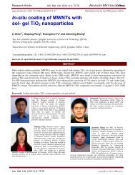
Fig. 1 shows the XRD patterns <str<strong>on</strong>g>of</str<strong>on</strong>g> ZnTe films with various<br />
thicknesses (650, 1000 <strong>and</strong> 3300 Å) deposited <strong>on</strong> the pre-<br />
R. Amutha<br />
deposited <str<strong>on</strong>g>copper</str<strong>on</strong>g> films <str<strong>on</strong>g>of</str<strong>on</strong>g> thickness (250 Å) <strong>on</strong> glass. ZnTe<br />
film <str<strong>on</strong>g>of</str<strong>on</strong>g> thickness 650 Å possesses hexag<strong>on</strong>al structure while<br />
<strong>on</strong> increasing the ZnTe film thickness up to 1000 Å, <strong>on</strong>e <str<strong>on</strong>g>of</str<strong>on</strong>g><br />
the dominant peaks (006) <str<strong>on</strong>g>of</str<strong>on</strong>g> hexag<strong>on</strong>al phase has<br />
diminished <strong>and</strong> cubic phase has been appeared. Further<br />
increasing the film thickness, all the peaks [(006), (009)<br />
<strong>and</strong> (0010] <str<strong>on</strong>g>of</str<strong>on</strong>g> hexag<strong>on</strong>al phase have diminished <strong>and</strong> those<br />
<str<strong>on</strong>g>of</str<strong>on</strong>g> <strong>on</strong>ly the cubic phase al<strong>on</strong>e remain. No peaks for metallic<br />
Cu or any other compound such as Cu2Te are observed.<br />
10 20 30 40 50 60<br />
2 (Degrees)<br />
Adv. Mat. Lett. 2013, 4(3), 225-229 Copyright © 2013 VBRI press 226<br />
Intensity (cps)<br />
160<br />
140<br />
120<br />
100<br />
80<br />
60<br />
40<br />
20<br />
0<br />
50<br />
40<br />
30<br />
20<br />
10<br />
0<br />
40<br />
30<br />
20<br />
10<br />
0<br />
(006)<br />
(111)<br />
(009)<br />
(009)<br />
(0010)<br />
(0010)<br />
t = 3300 Å<br />
t = 1000 Å<br />
t = 650 Å<br />
Fig. 1. X- ray diffractograms <str<strong>on</strong>g>of</str<strong>on</strong>g> vacuum evaporated <str<strong>on</strong>g>copper</str<strong>on</strong>g> doped ZnTe<br />
films.<br />
Therefore, all the <str<strong>on</strong>g>copper</str<strong>on</strong>g> atoms diffuse into the ZnTe<br />
film during the depositi<strong>on</strong> <str<strong>on</strong>g>of</str<strong>on</strong>g> ZnTe <strong>and</strong> influence the grain<br />
growth in the deposited ZnTe film. This phase change from<br />
hexag<strong>on</strong>al to cubic may be due to the decrease <str<strong>on</strong>g>of</str<strong>on</strong>g> <str<strong>on</strong>g>copper</str<strong>on</strong>g><br />
compositi<strong>on</strong> <strong>and</strong> as well as the increase <str<strong>on</strong>g>of</str<strong>on</strong>g> ZnTe<br />
compositi<strong>on</strong>. In these <strong>structural</strong> changes in <str<strong>on</strong>g>copper</str<strong>on</strong>g> doped<br />
polycrystalline films it is obvious that the diffusi<strong>on</strong> <strong>and</strong><br />
locati<strong>on</strong> <str<strong>on</strong>g>of</str<strong>on</strong>g> <str<strong>on</strong>g>copper</str<strong>on</strong>g> atoms play an important role. It could be<br />
thought that most <str<strong>on</strong>g>of</str<strong>on</strong>g> the <str<strong>on</strong>g>copper</str<strong>on</strong>g> atoms locate in the grain<br />
boundaries for as-grown <str<strong>on</strong>g>copper</str<strong>on</strong>g> doped films. On increasing<br />
temperature, some <str<strong>on</strong>g>of</str<strong>on</strong>g> native <str<strong>on</strong>g>copper</str<strong>on</strong>g> atoms can diffuse into<br />
grains <strong>and</strong> be thermally i<strong>on</strong>ized. The occupati<strong>on</strong> <str<strong>on</strong>g>of</str<strong>on</strong>g> <str<strong>on</strong>g>copper</str<strong>on</strong>g><br />
atoms in Zn sites <str<strong>on</strong>g>of</str<strong>on</strong>g> ZnTe lattice brings about the <strong>structural</strong><br />
transiti<strong>on</strong> in <str<strong>on</strong>g>copper</str<strong>on</strong>g> doped ZnTe films [22]. The grain size
Research Article Adv. Mat. Lett. 2013, 4(3), 225-229 ADVANCED MATERIALS Letters<br />
(D) <str<strong>on</strong>g>of</str<strong>on</strong>g> the films is estimated using Debye Scherrer’s<br />
formula [23],<br />
k<br />
D (1)<br />
cos<br />
where, k is the c<strong>on</strong>stant = 0.94, - the wavelength <str<strong>on</strong>g>of</str<strong>on</strong>g><br />
radiati<strong>on</strong>, - the full width half maximum <str<strong>on</strong>g>of</str<strong>on</strong>g> the<br />
corresp<strong>on</strong>ding peak <str<strong>on</strong>g>of</str<strong>on</strong>g> the XRD pattern <strong>and</strong> - the<br />
diffracti<strong>on</strong> angle.<br />
The micro strain () <strong>and</strong> the dislocati<strong>on</strong> density () <str<strong>on</strong>g>of</str<strong>on</strong>g><br />
the as grown films were estimated using the equati<strong>on</strong>s [24,<br />
25]<br />
cos<br />
<br />
<br />
4 <br />
<strong>and</strong><br />
1<br />
(3)<br />
2<br />
D<br />
The grain size, strain <strong>and</strong> dislocati<strong>on</strong> density are<br />
presented in Table 2. From this table, an appreciable<br />
increase in grain size is observed when comparing to the<br />
pure ZnTe films [26]. The observed phenomen<strong>on</strong> is due to<br />
the thin <str<strong>on</strong>g>copper</str<strong>on</strong>g> layer, which is known to be a good<br />
stimulator for grain growth in ZnTe films [22]. The<br />
decrease in grain size by increasing the ZnTe film thickness<br />
may be due to the decrease <str<strong>on</strong>g>of</str<strong>on</strong>g> <str<strong>on</strong>g>copper</str<strong>on</strong>g> compositi<strong>on</strong> <strong>and</strong> as<br />
well as the increase <str<strong>on</strong>g>of</str<strong>on</strong>g> ZnTe compositi<strong>on</strong>.<br />
Table 2. Structural parameters <strong>and</strong> b<strong>and</strong> gap energies <str<strong>on</strong>g>of</str<strong>on</strong>g> <str<strong>on</strong>g>copper</str<strong>on</strong>g> doped<br />
ZnTe thin films <str<strong>on</strong>g>of</str<strong>on</strong>g> different thicknesses.<br />
Thicknes<br />
s (Å)<br />
650<br />
1000<br />
3300<br />
hkl Grain<br />
size<br />
D (Å)<br />
006<br />
009<br />
0010<br />
009<br />
0010<br />
111<br />
Optical <strong>properties</strong><br />
816<br />
1002<br />
1715<br />
532<br />
952<br />
196<br />
Strain <br />
10 -3 (lin -<br />
2 m 4 )<br />
0.425<br />
0.346<br />
0.202<br />
0.651<br />
0.364<br />
1.769<br />
Dislocatio<br />
n density<br />
<br />
10 14<br />
(lin/m 2 )<br />
1.502<br />
0.996<br />
0.340<br />
3.533<br />
1.103<br />
26.030<br />
(2)<br />
B<strong>and</strong><br />
gap<br />
energ<br />
y (eV)<br />
2.17<br />
2.15<br />
2.00<br />
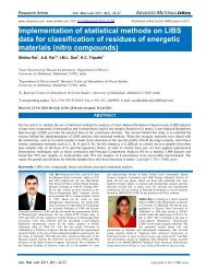
Fig. 2 shows the transmittance spectrum <str<strong>on</strong>g>of</str<strong>on</strong>g> <str<strong>on</strong>g>copper</str<strong>on</strong>g> doped<br />
ZnTe films. It is clearly observed that these films have very<br />
low transmittance when compared to the pure ZnTe films<br />
[26]. This decrease in the transmissi<strong>on</strong> can be attributed to<br />
the introducti<strong>on</strong> <str<strong>on</strong>g>of</str<strong>on</strong>g> impurity level between valance b<strong>and</strong><br />
<strong>and</strong> c<strong>on</strong>ducti<strong>on</strong> b<strong>and</strong> [27, 28]. The transmittance in the<br />
higher wavelength range is less than that <str<strong>on</strong>g>of</str<strong>on</strong>g> pure ZnTe<br />
films. This may be due to the fact that <str<strong>on</strong>g>copper</str<strong>on</strong>g> doped ZnTe<br />
films had higher carrier c<strong>on</strong>centrati<strong>on</strong> than pure ZnTe<br />
films, as absorpti<strong>on</strong> in the near-infrared regi<strong>on</strong> is mainly<br />
due to free carriers [29]. This is in good agreement with the<br />
earlier investigati<strong>on</strong> [30].<br />
The decrease <str<strong>on</strong>g>of</str<strong>on</strong>g> transmittance at higher doping levels<br />
may be attributed to the increased scattering <str<strong>on</strong>g>of</str<strong>on</strong>g> phot<strong>on</strong>s by<br />
crystal defects created by doping. The free carrier<br />
absorpti<strong>on</strong> <str<strong>on</strong>g>of</str<strong>on</strong>g> the phot<strong>on</strong>s` may also c<strong>on</strong>tribute to the<br />
observed reducti<strong>on</strong> in the <strong>optical</strong> transmissi<strong>on</strong> <str<strong>on</strong>g>of</str<strong>on</strong>g> heavily<br />
doped films [31-33].<br />
500 1000 1500 2000 2500<br />
Adv. Mat. Lett. 2013, 4(3), 225-229 Copyright © 2013 VBRI press.<br />
%T<br />
40<br />
30<br />
20<br />
10<br />
0<br />
W a v e l e n g t h ( n m )<br />
Fig. 2. Transmittance spectra <str<strong>on</strong>g>of</str<strong>on</strong>g> <str<strong>on</strong>g>copper</str<strong>on</strong>g> doped ZnTe films.<br />
Extincti<strong>on</strong> Coefficient (K f )<br />
1.5<br />
1.0<br />
0.5<br />
650 Å<br />
1000 Å<br />
3300 Å<br />
0.0<br />
400 500 600 700 800<br />
W a v e l e n g t h ( n m )<br />
650 Å<br />
1000 Å<br />
3300 Å<br />
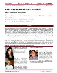
Fig. 3. Variati<strong>on</strong> <str<strong>on</strong>g>of</str<strong>on</strong>g> extincti<strong>on</strong> coefficient (k) <strong>on</strong> wavelength for <str<strong>on</strong>g>copper</str<strong>on</strong>g><br />
doped ZnTe films.<br />
The total absorpti<strong>on</strong> coefficient was calculated from<br />
transmittance measurements with the aid <str<strong>on</strong>g>of</str<strong>on</strong>g> the expressi<strong>on</strong><br />
[34]<br />
4kf = <br />
<br />
The extincti<strong>on</strong> co-efficient (k f ) can be calculated from<br />
the relati<strong>on</strong><br />
k<br />
f<br />
1<br />
2.303 log( )<br />
T0<br />
<br />
4<br />
t
where T0 is the transmittance <strong>and</strong> t the thickness <str<strong>on</strong>g>of</str<strong>on</strong>g> the film.<br />
( h) 2 (eV/cm) 2<br />
( h) 2 (eV/cm) 2<br />
( h) 2 (eV/cm) 2<br />
1.0x10 16<br />
5.0x10 15<br />
t = 6 5 0 Å<br />
0.0<br />
0.0 0.4 0.8 1.2 1.6 2.0 2.4 2.8<br />
4x10 15<br />
3x10 15<br />
2x10 15<br />
1x10 15<br />
5x10 14<br />
4x10 14<br />
3x10 14<br />
2x10 14<br />
1x10 14<br />
(a)<br />
(b)<br />
h ( e V )<br />
t = 1 0 0 0 Å<br />
0<br />
0.0 0.4 0.8 1.2 1.6 2.0 2.4 2.8<br />
(c)<br />
h ( e V )<br />
t = 3 3 0 0 Å<br />
0<br />
0.0 0.4 0.8 1.2 1.6 2.0 2.4 2.8<br />
h ( e V )<br />
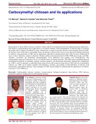
Fig. 4. The dependence <str<strong>on</strong>g>of</str<strong>on</strong>g> (αhυ) 2 vs hυ for <str<strong>on</strong>g>copper</str<strong>on</strong>g> doped ZnTe films <str<strong>on</strong>g>of</str<strong>on</strong>g><br />
thickness (a) 650 Å, (b) 1000 Å <strong>and</strong> c) 3300 Å.<br />
Fig. 3 shows the variati<strong>on</strong> <str<strong>on</strong>g>of</str<strong>on</strong>g> extincti<strong>on</strong> coefficient<br />
with wavelength for <str<strong>on</strong>g>copper</str<strong>on</strong>g> doped ZnTe thin films. A<br />
notable increase in extincti<strong>on</strong> coefficient is observed near<br />
the fundamental absorpti<strong>on</strong> edge in the <str<strong>on</strong>g>copper</str<strong>on</strong>g> doped films<br />
whereas it decreases in pure films. This may be due to the<br />
presence <str<strong>on</strong>g>of</str<strong>on</strong>g> <str<strong>on</strong>g>copper</str<strong>on</strong>g> in those films. It is also noted that the<br />
extincti<strong>on</strong> coefficient <str<strong>on</strong>g>of</str<strong>on</strong>g> the film decreases with decrease in<br />
R. Amutha<br />
<str<strong>on</strong>g>copper</str<strong>on</strong>g> compositi<strong>on</strong>. The electr<strong>on</strong>ic transiti<strong>on</strong> between<br />
valence <strong>and</strong> the c<strong>on</strong>ducti<strong>on</strong> b<strong>and</strong>s, is given by [35]-<br />
P<br />
αhυ = A hυ-E g<br />
where the magnitude <str<strong>on</strong>g>of</str<strong>on</strong>g> the exp<strong>on</strong>ent ‘p’ characterizes the<br />
type <str<strong>on</strong>g>of</str<strong>on</strong>g> transiti<strong>on</strong> <strong>and</strong> takes the values 1/2, 3/2, 2 <strong>and</strong> 3 for<br />
direct allowed, direct forbidden, indirect allowed <strong>and</strong><br />
indirect forbidden transiti<strong>on</strong>s respectively. In the above<br />
equati<strong>on</strong> ‘A’ is a c<strong>on</strong>stant, ‘Eg’ the <strong>optical</strong> b<strong>and</strong> gap <strong>and</strong><br />
‘ hυ ’ the energy <str<strong>on</strong>g>of</str<strong>on</strong>g> phot<strong>on</strong>.<br />
Fig. 4 shows (αhυ) 2 against the phot<strong>on</strong> energy (hυ) for<br />
<str<strong>on</strong>g>copper</str<strong>on</strong>g> doped ZnTe films, indicating the possible <strong>optical</strong><br />
transiti<strong>on</strong> is <str<strong>on</strong>g>of</str<strong>on</strong>g> direct-allowed type <strong>and</strong> the b<strong>and</strong> gap<br />
energies are given in Table 2.<br />
The direct b<strong>and</strong> gap values these <str<strong>on</strong>g>copper</str<strong>on</strong>g> doped films<br />
decreased appreciably when compared to pure ZnTe films,<br />
which may be attributed to the segregati<strong>on</strong> <str<strong>on</strong>g>of</str<strong>on</strong>g> impurities at<br />
the grain boundaries. Similar observati<strong>on</strong> has been made by<br />
Pal et al for In doped ZnTe films [36]. The appreciable<br />
decrease in the b<strong>and</strong> gap <str<strong>on</strong>g>of</str<strong>on</strong>g> <str<strong>on</strong>g>copper</str<strong>on</strong>g> doped films may also be<br />
caused by the presence <str<strong>on</strong>g>of</str<strong>on</strong>g> internal electric fields associated<br />
with the defects <strong>and</strong> by the changes in compositi<strong>on</strong> <str<strong>on</strong>g>of</str<strong>on</strong>g> the<br />
films.<br />
C<strong>on</strong>clusi<strong>on</strong><br />
Copper doped ZnTe thin films were deposited <strong>on</strong>to wellcleaned<br />
glass substrates by thermal evaporati<strong>on</strong>. The<br />
decrease <str<strong>on</strong>g>of</str<strong>on</strong>g> atomic percentage value <str<strong>on</strong>g>of</str<strong>on</strong>g> <str<strong>on</strong>g>copper</str<strong>on</strong>g> with<br />
increase <str<strong>on</strong>g>of</str<strong>on</strong>g> the ZnTe film thickness is c<strong>on</strong>firmed by EDX<br />
analysis. The X-ray diffracti<strong>on</strong> analysis indicates that the<br />
films undergo a phase change from hexag<strong>on</strong>al to cubic<br />
structure. Copper doped ZnTe films have very low<br />
transmittance when compared to pure ZnTe films. A sharp<br />
increase in extincti<strong>on</strong> coefficient is observed near the<br />
fundamental absorpti<strong>on</strong> edge. The <strong>optical</strong> transiti<strong>on</strong> <str<strong>on</strong>g>of</str<strong>on</strong>g><br />
these films is found to be direct allowed.<br />
Reference<br />
1. Cho<strong>on</strong>g Hyun Chung. Journal <str<strong>on</strong>g>of</str<strong>on</strong>g> the Korean Physical Society. 1969,<br />
2, 462.<br />
DOI: 10.3938/jkps.1.112<br />
2. Rao, G.K.; Bangera, K.V.; Shivakumar. G.K. Materials Research<br />
Bulletin. 2010, 45, 1357.<br />
DOI: 10.1016/j.materresbull.2010.06.050<br />
3. Baratii, A.; Klein, A.; Jaegermann, W. Thin Solid Films. 2009, 517,<br />
2149<br />
DOI: 10.1016/j.tsf.2008.10.078<br />
4. Mazumdar, N.; Sarma, R.; Sarma, B.K.; Das, H.L. Bull. Mater. Sci.<br />
2006, 29(1) 11.<br />
5. Aven, M.; Segall, B. Phys. Rev. 1963, 130, 81.<br />
DOI: 10.1103/PhysRev.130.81<br />
6. Aven, M. J. Appl. Phys. 1967, 38, 4421.<br />
DOI: 10.1063/1.1709141<br />
7. Thomas, D.G.; Sadowski, E.A. J. Phys. Chem. Solids. 1964, 25, 395.<br />
DOI: 10.1016/0022-3697(64)90005-8<br />
8. Smith, F.T.J. J. Phys. Chem. Solids. 1971, 32, 2201.<br />
DOI: 10.1016/S0022-3697(71)80398-0<br />
9. Kalita, P.K.; Sarma, B.K.; Das, H.L. Indian Journal <str<strong>on</strong>g>of</str<strong>on</strong>g> Pure <strong>and</strong><br />
Applied Physics. 1999, 37, 885.<br />
10. BaEtzner, D.L.; Wendt, R.; Romeo, A.; Zogg, H.; Tiwari, A.N. Thin<br />
Solid Films. 2000, 361-362, 463.<br />
DOI: 10.1016/S0040-6090(99)00842-1<br />
11. Rioux, D.; Niles, D.W.; Hochst, H. J. Appl. Phys. 1993, 73(12),<br />
8381.<br />
Adv. Mat. Lett. 2013, 4(3), 225-229 Copyright © 2013 VBRI press 228
Research Article Adv. Mat. Lett. 2013, 4(3), 225-229 ADVANCED MATERIALS Letters<br />
DOI: 10.1063/1.353406<br />
12. Amin, N.; Yamada, A.; K<strong>on</strong>agai, M. Jpn. J. Appl. Phys. 2002, 41,<br />
2834.<br />
DOI: 10.1143/JJAP.41.2834<br />
13. Spath, B.; Fritsche, J.; Sauberlich, F.; Klein, A.; Jaegermann. W.,<br />
Thin Solid Films. 2005, 481, 204.<br />
DOI: 10.1016/j.tsf.2004.11.073<br />
14. Chaure, N.B.; Nair, J.P.; Jayakrishan, R.; Ganesan, V.; P<strong>and</strong>ey, R.K.<br />
Thin Solid Films. 1998, 324, 78.<br />
DOI: 10.1016/S0040-6090(97)01209-1<br />
15. Feng, L.; Mao, D.; Tang, J.; Collins, R.T.; Trefny, J.U. J. Electr<strong>on</strong>.<br />
Mater. 1996, 25, 1442.<br />
DOI: 10.1007/BF02655377<br />
16. Gessert, T.A.; Mas<strong>on</strong>, A.R.; Sheld<strong>on</strong>, P.; Swartzl<strong>and</strong>er, A.B.; Niles,<br />
D.; Coutts ,T.J. J. Vac. Sci. Technol. A. 1996, 14(3), 806.<br />
DOI: 10.1116/1.580394<br />
17. Gessert, T.A.; Coutts, T.J. 12 th NREL Photovoltaic Program Review<br />
Proc. 1993, 345.<br />
18. Chaure, N.B.; Nair, J.P.; Jayakrishan, R.; Ganesan, V.; P<strong>and</strong>ey, R.K.<br />
Thin Solid Films. 1998, 324,78.<br />
DOI: 10.1016/S0040-6090(97)01209-1<br />
19. Athwal, I.S.; Bedi, R.K. J. Appl. Phys. 1988, 64(11), 6345.<br />
DOI: 10.1063/1.342097<br />
20. Koboyashi, S.I.; Saito, N. Jpn. J. Appl. Phys. 1980,19, 1199.<br />
DOI: 10.1143/JJAP.19.1199<br />
21. Tolansky, S. Multiple beam interferometry <str<strong>on</strong>g>of</str<strong>on</strong>g> surfaces <strong>and</strong> films<br />
(Oxford University Press, New Jercy) 1948.<br />
22. Patel, S.M.; Patel, N.G. Thin solid Films. 1984, 122(4), 297.<br />
DOI: 10.1016/0040-6090(84)90030-0<br />
23. Salunkhe, M.M.; Patil, S. M.; Mane, R. M.; Patil, S. V.; Bhosale, P.<br />
N. Adv. Mat. Lett. 2012, 3(2), 71.<br />
DOI: 10.5185/amlett.2012.1304<br />
24. Kalita, P.K.; Sarma, B.K; Das, H.L. Bull. Mater. Sci. 2000, 23, 313.<br />
25. Williams<strong>on</strong>, G.K.; Smallman, R.E. Phil. Mag. 1956, 1, 34.<br />
DOI: 10.1080/14786435608238074<br />
26. Amutha, R.; Subbarayan, A.; Sathyamoorthy, R.; Natarajan, K.;<br />
Velumani, S. Journal <str<strong>on</strong>g>of</str<strong>on</strong>g> New Materials for Electrochemical Systems.<br />
2007, 10(1), 27.<br />
27. Schroder, D.K. Semic<strong>on</strong>ductor Material Device Characterizati<strong>on</strong>; 2 nd<br />
Edn. Wiley, New York. 1998.<br />
28. Rose, R.M.; Shepard, L.A.; Wulff, J. The Structure <strong>and</strong> Properties <str<strong>on</strong>g>of</str<strong>on</strong>g><br />
Materials, John Wiley <strong>and</strong> S<strong>on</strong>s Inc., New York. 1967, Vol.4.<br />
29. Matsubara, K.; F<strong>on</strong>s, P.; Iwata, K.; Yamada, A.; Nike S. Thin Solid<br />
Films. 2002, 422, 176.<br />
DOI: 10.1016/S0040-6090(02)00965-3<br />
30. M<strong>on</strong>dal, A.; Chaudhuri, S.; Pal, A.K. Thin Solid Films. 1989, 176,<br />
L183.<br />
DOI: 10.1016/0040-6090(89)90107-7<br />
31. Fistul, V.I. Heavily Doped Semic<strong>on</strong>ductors, Plenum, New York,<br />
P.208.<br />
32. Joseph, B.; Manoj, P.K.; Vaidyan, V.K. Ceramics Internati<strong>on</strong>al.<br />
2006, 32, 487.<br />
DOI: 10.1016/j.ceramint.2005.03.029<br />
33. Upadyay, J.P.; Viswakarma, S.R.; Pradad, H.C. Thin solid Films.<br />
1989,169, 195.<br />
DOI: 10.1016/0040-6090(89)90701-3<br />
34. Prasada Rao, K.; Hussain, O.Md.; Reddy, H.T.R.; Reddy, P.S.;<br />
Uthanna, S.; Naidu, B.S.; Jayarama Reddy, P. Optical Materials.<br />
1996, 5, 63.<br />
DOI: 10.1016/0925-3467(95)00041-0<br />
35. Dixit, G.; Singh, J.P.; Srivastava, R.C.; Agrawal, H.M.; Chaudhary,<br />
R.J. Adv. Mat. Lett. 2012, 3(1), 21.<br />
DOI: 10.5185/amlett.2011.6280<br />
36. Pal, U.; Saha, S.; Chaudhuri, A.K.; Rao, V.V.; Banedrjee, H.D. J.<br />
Phys. D: Appl. Phys. 1989, 22, 965.<br />
DOI: 10.1088/0022-3727/22/7/014<br />
Adv. Mat. Lett. 2013, 4(3), 225-229 Copyright © 2013 VBRI press.