Synthesis of carbon nanowires by SHI irradiation of fullerene C70 ...
Synthesis of carbon nanowires by SHI irradiation of fullerene C70 ...
Synthesis of carbon nanowires by SHI irradiation of fullerene C70 ...

You also want an ePaper? Increase the reach of your titles
YUMPU automatically turns print PDFs into web optimized ePapers that Google loves.
Research Article Adv. Mat. Lett. 2013, 4(6), 413-417 ADVANCED MATERIALS Letters<br />
www.amlett.com, www.amlett.org, DOI: 10.5185/amlett.2012.ib.105<br />
"Nanostructuring <strong>by</strong> electrons, photons and ions" Special Issue Published online <strong>by</strong> the VBRI press in 2013<br />
<strong>Synthesis</strong> <strong>of</strong> <strong>carbon</strong> <strong>nanowires</strong> <strong>by</strong> <strong>SHI</strong><br />
<strong>irradiation</strong> <strong>of</strong> <strong>fullerene</strong> <strong>C70</strong> thin film<br />
R. Singhal 1* , A. Tripathi 2 , D. K. Avasthi 2<br />
1 Malaviya National Institute <strong>of</strong> Technology Jaipur, JLN Marg, Jaipur 302017, India<br />
2 Inter University Accelerator Centre, Aruna Asaf Ali Marg, New Delhi, India<br />
* Corresponding author. E-mail: rahuliuac@gmail.com<br />
Received: 16 March 2012, Revised: 22 July 2012 and Accepted: 26 July 2012<br />
ABSTRACT<br />
Electrically conducting <strong>carbon</strong> <strong>nanowires</strong>, all parallel to each other and embedded in <strong>fullerene</strong> <strong>C70</strong> matrix are created <strong>by</strong> swift<br />
heavy ion <strong>irradiation</strong> <strong>of</strong> thin <strong>fullerene</strong> <strong>C70</strong> film at low fluences (up to 10 10 ions/cm 2 ). The conductivity <strong>of</strong> the wires is several<br />
orders <strong>of</strong> magnitude higher than the surrounding material and it is due to the transformation <strong>of</strong> <strong>fullerene</strong> into amorphous <strong>carbon</strong><br />
within each ion hit zone. These conducting <strong>nanowires</strong> are evidenced <strong>by</strong> conducting atomic force microscopy. The typical<br />
diameter <strong>of</strong> the conducting tracks is observed to be about 11-21 nm. Copyright © 2013 VBRI press.<br />
Keywords: Nanowires; <strong>fullerene</strong>; <strong>irradiation</strong>.<br />
Rahul Singhal is currently working as INSPIRE<br />
Faculty Fellow at National Physical Laboratory,<br />
New Delhi. He received M.Sc. degree in Physics<br />
from Indian Institute <strong>of</strong> Technology, Roorkee<br />
and completed Ph.D. at Inter University<br />
Accelerator Centre New Delhi in affiliation with<br />
Jawahar Lal Nehru University New Delhi. His<br />
main areas <strong>of</strong> research are (1) synthesis <strong>of</strong> metal<br />
nanoparticles in different <strong>carbon</strong>s such as C60,<br />
<strong>C70</strong> and amorphous <strong>carbon</strong>, (2) swift heavy ion<br />
induced modifications <strong>of</strong> <strong>carbon</strong> based<br />
nanocomposites, (3) tuning <strong>of</strong> surface plasmon resonance frequency <strong>of</strong><br />
metal-<strong>carbon</strong> nanocomposites, (4) ion <strong>irradiation</strong> effects on shape<br />
memory alloys thin films.<br />
D. K. Avasthi is working as Scientist at IUAC,<br />
New Delhi. He is the present group leader for<br />
Materials Science Group and Radiation Biology<br />
Group at IUAC, New Delhi. He has keen interest<br />
on in-situ/online measurements during ion<br />
<strong>irradiation</strong> like (i) electronic sputtering <strong>by</strong> online<br />
ERDA (ii) phase transformation and<br />
growth/reduction <strong>of</strong> nanoparticle size <strong>by</strong> in-situ<br />
XRD, (iii) on-line measurement <strong>of</strong> gas release<br />
during ion <strong>irradiation</strong> (iv) in-situ Raman<br />
spectrometer (being setup). He is also interested in establishment <strong>of</strong> role<br />
<strong>of</strong> thermal spike in <strong>SHI</strong> induced mixing in metal/Si and metal/metal<br />
systems, synthesis and engineering <strong>of</strong> nanostructures <strong>by</strong> ion beams, ion<br />
beam interaction with nanodimensional systems, synthesis <strong>of</strong> metal<br />
nanoparticles embedded in different matrices <strong>by</strong> atom beam co-sputtering<br />
and understanding <strong>of</strong> the same <strong>by</strong> simulation, creation <strong>of</strong> functional<br />
surfaces <strong>by</strong> ion beams etc.<br />
Ambuj Tripathi is Scientist at Inter University<br />
Accelerator Centre (IUAC), New Delhi. He is<br />
in-charge <strong>of</strong> Materials Science (online<br />
experimental facilities) and SPM Lab at IUAC.<br />
His main areas <strong>of</strong> research are (i) Ion beam<br />
modification <strong>of</strong> surfaces and (ii) Ion beam<br />
induced synthesis and modification <strong>of</strong><br />
nanoparticles. He has played a key role in the<br />
setting up <strong>of</strong> the experimental beam line and insitu<br />
facilities such as in-situ XRD, in-situ UHV<br />
STM, in-situ QMA setup. He did his Ph.D. from University <strong>of</strong> Allahabad<br />
in 2006 on the Study <strong>of</strong> Irradiation Effects on Surfaces.<br />
Adv. Mat. Lett. 2013, 4(6), 413-417 Copyright © 2013 VBRI press.
Introduction<br />
Electrically conducting <strong>nanowires</strong> are potential candidates<br />
for application in flat panel display devices due to their<br />
interesting field emission properties [1–2]. An array <strong>of</strong><br />
parallel conducting <strong>nanowires</strong> in some insulating matrix is a<br />
good substitute for electron emitters in order to increase the<br />
pixel density in display devices. Several methods have been<br />
developed for the fabrication <strong>of</strong> <strong>nanowires</strong> arrays including<br />
catalytic growth [3], template methods [4,5], Langmuir<br />
Blodgett and electrospinning [6]. The important aspect for<br />
the creation <strong>of</strong> <strong>nanowires</strong> is the development <strong>of</strong> new<br />
methods which can provide large scale and controllable<br />
production <strong>of</strong> these <strong>nanowires</strong>, especially for aligned<br />
<strong>nanowires</strong>. The electron beam lithography can help in the<br />
formation <strong>of</strong> catalyst sites for aligned production <strong>of</strong><br />
<strong>nanowires</strong>, but this serial technique is too slow for scalable<br />
mass production.<br />
Ion beam methods are interesting because <strong>of</strong> its unique<br />
feature <strong>of</strong> depositing large electronic energy (for swift<br />
heavy ions) in a confined cylindrical nanozone in a<br />
controlled fashion. Ion beam <strong>irradiation</strong> is known to be a<br />
valuable and innovative tool for engineering and<br />
modification <strong>of</strong> materials at nano/atomic scale. Swift heavy<br />
ions (ions having velocities close to or higher than the<br />
orbital electron velocity) passing through materials lose<br />
energy along their path dominantly to the electronic<br />
subsystem and each ion induces damages in the material<br />
within diameters <strong>of</strong> several nanometers width. Carbon<br />
<strong>nanowires</strong>/nanochannels have successfully been<br />
synthesized using swift heavy ion <strong>irradiation</strong> in <strong>fullerene</strong><br />
C60 and some polymer thin films [7-9]. In a comparative<br />
study <strong>of</strong> structural stability <strong>of</strong> <strong>fullerene</strong> C60 and <strong>C70</strong> with<br />
swift heavy ion <strong>irradiation</strong>, it has been shown that <strong>fullerene</strong><br />
<strong>C70</strong> molecule is marginally stable than <strong>fullerene</strong> C60 against<br />
swift heavy ion <strong>irradiation</strong> [10]. The radius <strong>of</strong> ion track was<br />
found to be higher for <strong>fullerene</strong> C60 than that <strong>of</strong> <strong>C70</strong> for<br />
same electronic energy loss. Also the polymerization <strong>of</strong><br />
<strong>fullerene</strong> C60 at low fluences has been reported many times<br />
[11-12] which was a major cause for the mismatch between<br />
the fluence and ion track areal density. There is no such<br />
polymerization has been reported so far in <strong>C70</strong> and therefore<br />
<strong>C70</strong> is another interesting material to form <strong>carbon</strong> <strong>nanowires</strong><br />
using swift heavy ion <strong>irradiation</strong> technique. Therefore, swift<br />
heavy ion <strong>irradiation</strong> has been used in present work to<br />
synthesize conducing <strong>carbon</strong> <strong>nanowires</strong> in <strong>fullerene</strong> <strong>C70</strong><br />
matrix. To the best <strong>of</strong> our knowledge, first time conducting<br />
<strong>nanowires</strong> are synthesized in <strong>fullerene</strong> <strong>C70</strong> films <strong>by</strong> our<br />
group. Fullerene, having resistivity almost like insulators<br />
becomes conducting due to its transformation into<br />
amorphous <strong>carbon</strong> within ion track region [13-16] and in<br />
this manner, conduction <strong>nanowires</strong> <strong>of</strong> amorphous <strong>carbon</strong><br />
can be formed in insulating <strong>fullerene</strong> matrix.<br />
Experimental<br />
Fullerene <strong>C70</strong> thin films with a thickness <strong>of</strong> ~200 nm were<br />
deposited on 50 nm thick Au layers on glass substrate. The<br />
need to deposit Au layer between glass substrate and<br />
<strong>fullerene</strong> <strong>C70</strong> film was to facilitate the characterization <strong>of</strong><br />
conducting channels <strong>by</strong> conducting atomic force<br />
microscopy (C-AFM), as shown in Fig. 1. Therefore,<br />
initially a 50 nm Au films were deposited on glass substrate<br />
Singhal, Tripathi and Avasthi<br />
<strong>by</strong> resistive heating and above it, <strong>fullerene</strong> <strong>C70</strong> film was<br />
deposited <strong>by</strong> sublimation <strong>of</strong> <strong>C70</strong> pellet. The pellet was made<br />
from <strong>C70</strong> powder (Alfa Aesar 99.9 %) <strong>by</strong> applying suitable<br />
pressure on it in a 3 mm thick dye. The base pressure in the<br />
chamber before and after the evaporation was 7 x 10 -7 and<br />
3 x 10 -6 torr respectively. The deposition was performed <strong>by</strong><br />
sublimation <strong>of</strong> <strong>C70</strong> pellet at a rate <strong>of</strong> ~ 1.0 nm/sec and <strong>by</strong><br />
passing a current <strong>of</strong> 170 A in a W boat. A Quartz crystal<br />
oscillator was used to measure the thickness <strong>of</strong> the film<br />
during deposition. A small area <strong>of</strong> the Au film was masked<br />
so that it can be used as a contact for C-AFM<br />
measurements.<br />
Fig. 1. Schematic showing the arrangements for the measurements <strong>of</strong><br />
current across the <strong>nanowires</strong><br />
The <strong>C70</strong> thin films were irradiated with 100 MeV Ag<br />
ions at fluences <strong>of</strong> 1x10 9 , 3x10 9 , and 1x10 10 ions/cm 2 using<br />
15 UD tandem Pelletron accelerator at IUAC, New Delhi.<br />
In the case <strong>of</strong> 100 MeV Ag ions, the electronic (Se) and<br />
nuclear (Sn) energy losses in <strong>C70</strong> are ~ 1.2 x 10 3 eV/Å and ~<br />
15.4 eV/Å respectively and the range <strong>of</strong> Ag ions in <strong>C70</strong> is<br />
15.6 m as calculated <strong>by</strong> SRIM 2003 (The Stopping and<br />
Range <strong>of</strong> Ions in Matter) programme [17]. The range is<br />
much higher than the thickness <strong>of</strong> the film (~ 200 nm) so<br />
that all the ions are buried inside the substrate after<br />
depositing energy into the <strong>fullerene</strong> film. The electronic<br />
energy loss in the entire thickness <strong>of</strong> the film is uniform, as<br />
estimated <strong>by</strong> the SRIM simulation. The fluences were kept<br />
low, so as to avoid the overlap <strong>of</strong> the ion tracks. The ion<br />
beam was scanned in area <strong>of</strong> 1 x 1 cm 2 <strong>by</strong> an<br />
electromagnetic scanner. The C-AFM measurements were<br />
performed on the irradiated and pristine samples using the<br />
instrument Nanoscope III a SPM. The I-V measurements in<br />
C-AFM mode were also performed on the irradiated<br />
samples. Micro-Raman data <strong>of</strong> as-deposited film was<br />
recorded with a Renishaw in-Via Raman microscope using<br />
Ar ion laser excitation at 514 nm and at room temperature.<br />
To avoid any heating effect, the laser beam was focused at<br />
very low power (< 2 mW, 20 X objective).<br />
Results and discussion<br />
Raman spectroscopy<br />
Fullerene <strong>C70</strong> molecule is <strong>of</strong> reduced symmetry (D5h point<br />
group) compared to <strong>fullerene</strong> C60 and therefore the number<br />
<strong>of</strong> vibrational modes <strong>of</strong> this molecule increases<br />
dramatically. For pure <strong>C70</strong> at room temperature, 53 Raman<br />
active modes are predicted (12 A1' +22 E2' +19 E1") from<br />
group theory and various first principle theories [18-19].<br />
Fig. 2 depicts the typical Raman spectra <strong>of</strong> a pure <strong>C70</strong> thin<br />
Adv. Mat. Lett. 2013, 4(6), 413-417 Copyright © 2013 VBRI press 414
Research Article Adv. Mat. Lett. 2013, 4(6), 413-417 ADVANCED MATERIALS Letters<br />
film on glass substrate. The peaks observed are consistent<br />
with those previously reported in literature and are<br />
attributed to the internal modes <strong>of</strong> <strong>C70</strong> molecule. The<br />
presence <strong>of</strong> these peaks in as-deposited film confirms that<br />
<strong>fullerene</strong> molecules are intact after the deposition <strong>of</strong> film.<br />
Fig. 2. Raman spectra <strong>of</strong> <strong>C70</strong> thin film on glass substrate. The intense<br />
peaks are marked <strong>by</strong> their wavenumbers<br />
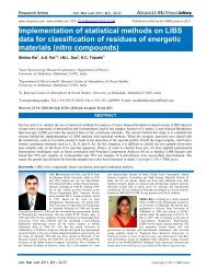
Fig. 3. AFM image, in conducting mode, <strong>of</strong> the <strong>fullerene</strong> <strong>C70</strong> thin film<br />
(200 nm) irradiated <strong>by</strong> 100 MeV Ag ions at the fluences <strong>of</strong> 1 x 10 9 (figure<br />
a), 3 x 10 9 (figure a) and 1 x 10 10 (figure c) ions/cm 2 . The vertical<br />
<strong>nanowires</strong> represent the current flowing through the conducting ion<br />
tracks.<br />
Conducting AFM measurement<br />
Conducting AFM 3D current images <strong>of</strong> the <strong>fullerene</strong> <strong>C70</strong><br />
film irradiated with 100 MeV Ag ions at a fluence <strong>of</strong> 1 x<br />
10 9 , 3 x 10 9 and 1 x 10 10 ions/cm 2 are shown in Fig. 3. The<br />
Z axis <strong>of</strong> Fig. represents the current. The number <strong>of</strong> ion<br />
tracks per unit area increases with fluence. It can be clearly<br />
seen that the current in ion tracks is significantly higher<br />
than that <strong>of</strong> the region not hit <strong>by</strong> the ions. The sectional<br />
analysis (not shown) reveals that the diameter <strong>of</strong><br />
conducting zone varies from 11 to 21 nm. Here it is<br />
interesting to note that in case <strong>of</strong> <strong>fullerene</strong> C60, the diameter<br />
<strong>of</strong> conducting zone measured using sectional analysis <strong>of</strong> C-<br />
AFM measurements varied from 40 to 100 nm (although<br />
actual ion track diameter in <strong>fullerene</strong> C60 is few nm), which<br />
was due to the polymerization <strong>of</strong> irradiated <strong>fullerene</strong> C60 in<br />
the annular region surrounding the core amorphous region<br />
which gave the possible extra path for the current to flow.<br />
But as there is no polymerization in <strong>fullerene</strong> <strong>C70</strong>, much<br />
smaller (compared to that <strong>of</strong> C60) and actual diameter (11-<br />
21 nm) <strong>of</strong> conducting zones is measured <strong>by</strong> C-AFM<br />
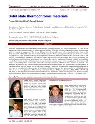
measurements. The 2D current image <strong>of</strong> <strong>C70</strong> sample <strong>by</strong><br />
irradiated at a fluence <strong>of</strong> 3 x 10 9 ions/cm 2 is shown in Fig.<br />
4. The tracks as seen are elongated due to ‘‘electronic<br />
drift’’ during the measurement and is not related with the<br />
direction <strong>of</strong> the beam which was perpendicular to the<br />
sample surface.<br />
Fig. 4. 2D current image <strong>of</strong> a <strong>C70</strong> thin film irradiated with 100 MeV Ag<br />
ions at a fluence <strong>of</strong> 3 x 10 9 ions/cm 2 . The conducting impact sites are<br />
shown <strong>by</strong> high current bright zones.<br />
Table 1. Table showing the number <strong>of</strong> tracks, theoretically and<br />
experimentally, for the <strong>irradiation</strong> <strong>of</strong> <strong>C70</strong> thin films <strong>by</strong> 100 MeV Ag ions<br />
at different fluences.<br />
The conducting impact sites are shown <strong>by</strong> local increase<br />
<strong>of</strong> current. The image clearly shows high current zones<br />
separated <strong>by</strong> insulating zones. We determined the ion track<br />
density using 2D C-AFM current images at different<br />
Adv. Mat. Lett. 2013, 4(6), 413-417 Copyright © 2013 VBRI press.
fluences and compared them with those calculated<br />
theoretically <strong>by</strong> taking the value <strong>of</strong> ion track diameter from<br />
our previous work [16]. These values are given in Table 1.<br />
Experimental value for number <strong>of</strong> tracks is the average<br />
value taken over 3 - 4 different areas <strong>of</strong> 2D current images.<br />
There is some mismatch between theoretical and<br />
experimental values for number <strong>of</strong> ion tracks, which may be<br />
due to the following reasons: (i) a small mismatch is<br />
possible because <strong>of</strong> the fluence uncertainty (maximux up to<br />
20%) as ion beam current can have some small variation<br />
during the <strong>irradiation</strong> time period, (ii) since the ion hits<br />
randomly, it is possible that some ion tracks are either<br />
overlapping or probed simultaneously due to close<br />
proximity <strong>of</strong> two tracks, (iii) the finite size <strong>of</strong> tip may have<br />
influence, (iv) possibility <strong>of</strong> lateral conduction with the<br />
neighbouring tracks.<br />
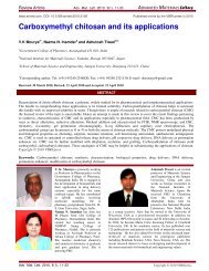
Fig. 5. The current vs voltage (I-V) characteristics at the ion tracks at<br />
different fluences <strong>of</strong> 100 MeV Ag ions as measured in conducting atomic<br />
force microscopy.<br />
Detailed I-V measurements on ion hit regions in the<br />
samples irradiated with increasing fluence at energy <strong>of</strong> 100<br />
MeV Ag are shown in Fig. 5 and confirm the increased<br />
current in the ion tracks. The increase in local conductivity<br />
at higher fluence is due to the overlapping <strong>of</strong> ion tracks.<br />
There is likelihood <strong>of</strong> conduction through the surrounding<br />
<strong>of</strong> tracks due to a close proximity. Since the ion tracks are<br />
formed along the ion path and the ion beam is incident<br />
perpendicular to the surface <strong>of</strong> <strong>fullerene</strong> film, the<br />
conducting <strong>nanowires</strong> are perpendicular to the surface and<br />
all the conducting channels are parallel to each other. The<br />
conversion <strong>of</strong> <strong>fullerene</strong> into amorphous <strong>carbon</strong> form<br />
depends upon electronic energy deposition <strong>by</strong> ions along<br />
the ion paths. We calculated the conductivity <strong>of</strong> the formed<br />
conducing wires <strong>by</strong> measuring the diameter and current in<br />
conducting AFM images. The conductivity <strong>of</strong> the wires for<br />
100 MeV Ag ion irradiated films is about 7.6 x 10 -4 S/cm<br />
for the track diameter <strong>of</strong> 12 nm and 1.8 nA current<br />
corresponding to applied bias <strong>of</strong> 2 V, which is orders <strong>of</strong><br />
magnitude higher than the conductivity <strong>of</strong> the pristine<br />
<strong>fullerene</strong> <strong>C70</strong> film (~ 10 -6 S/cm) [16]. Here it is worth<br />
mentioning that the conductivity <strong>of</strong> <strong>carbon</strong> <strong>nanowires</strong> for<br />
the <strong>fullerene</strong> C60 film is ~ 10 -2 S/cm [7] when film was<br />
irradiated with 180 MeV Ag ions (Se ~ 1.1 x 10 3 eV/Å),<br />
whereas in the case <strong>of</strong> <strong>fullerene</strong> <strong>C70</strong> film, the conductivity<br />
Singhal, Tripathi and Avasthi<br />
<strong>of</strong> <strong>nanowires</strong> is 7.6 x 10 -4 S/cm for the 100 MeV Ag ions<br />
(Se ~ 1.2 x 10 3 eV/Å). The higher conductivity <strong>of</strong><br />
<strong>nanowires</strong> in the case <strong>of</strong> <strong>fullerene</strong> C60 is understandable<br />
because pristine <strong>fullerene</strong> C60 thin film is more conducting<br />
than that <strong>of</strong> pristine <strong>C70</strong> [10].<br />
Different theoretical approaches exists in literature to<br />
explain the ion track formation, out <strong>of</strong> them, most important<br />
is thermal spike model [20-22]. The swift heavy ion passing<br />
through <strong>fullerene</strong> film induces a temperature spike via<br />
transfer <strong>of</strong> its energy to lattice through electron-phonon<br />
coupling and this temperature spike causes a transient melt<br />
in a track core <strong>of</strong> a few nm in diameter. The <strong>fullerene</strong><br />
structure is completely destroyed in this transient melt<br />
phase and only amorphous <strong>carbon</strong> is left inside the ion hit<br />
cylindrical zone. The surrounding region <strong>of</strong> the track core<br />
is also heated transiently <strong>by</strong> electrons as heat waves. In fact,<br />
the track and surrounding region has a time dependent<br />
temperature pr<strong>of</strong>ile. The fast quenching (~ 10 14 K/Sec) <strong>of</strong><br />
the temperature spike results in the formation <strong>of</strong> ion track.<br />
Thus, under the ion impact <strong>fullerene</strong> <strong>C70</strong> molecule breaks<br />
up into individual <strong>carbon</strong> atoms which disperse between the<br />
remaining <strong>fullerene</strong> spheres with the dispersed <strong>carbon</strong><br />
atoms serving as a centre for hopping conductivity. These<br />
broken <strong>carbon</strong> atoms along the ion tracks serve as<br />
conducting <strong>nanowires</strong> in insulating matrix (<strong>fullerene</strong> film).<br />
The advantages <strong>of</strong> ion <strong>irradiation</strong> technique to<br />
synthesize <strong>nanowires</strong> are: (i) the density <strong>of</strong> conducting<br />
wires is found to be proportional to the fluence, which<br />
indicates that the number <strong>of</strong> conducting wires per unit area<br />
can be controlled <strong>by</strong> ion fluence, (ii) the orientation <strong>of</strong><br />
conducting <strong>nanowires</strong> with respect to the substrate can be<br />
engineered <strong>by</strong> simply changing the incidence angle <strong>of</strong> the<br />
ion beam, (iii) length <strong>of</strong> the conducting wires can simply be<br />
increased <strong>by</strong> irradiating the thicker film <strong>of</strong> <strong>fullerene</strong> <strong>C70</strong>.<br />
Conclusion<br />
The present work demonstrates the formation <strong>of</strong> conducting<br />
<strong>nanowires</strong>, parallel to each other in <strong>fullerene</strong> <strong>C70</strong> films <strong>by</strong><br />
the 100 MeV Ag ion <strong>irradiation</strong>. It is explained <strong>by</strong><br />
transformation <strong>of</strong> <strong>fullerene</strong> into amorphous <strong>carbon</strong> within<br />
each ion hit region. The diameter <strong>of</strong> formed conducting<br />
zones varies from 11 to 21 nm. The current–voltage<br />
measurements show that the conductivity <strong>of</strong> tracks<br />
increases with increasing fluence.<br />
Acknowledgement<br />
The author (R. Singhal) is thankful to IUAC Pelletron group for providing<br />
stable ion beam at a very low current due to which, it was possible to<br />
irradiate the samples at such a low fluences. Department <strong>of</strong> Science and<br />
Technology New Delhi (DST), India is highly acknowledged for<br />
providing experimental characterization facilities through “Nanomission”<br />
and “IRHPA” projects.<br />
Reference<br />
1. Vila, L.; Vincent, P.; Pra-De Dauginet L.; and Pirio, G. Nano Lett.<br />
2004, 4, 521.<br />
2. Yan, H.; Park, S.H.; Finkelstein G.; Reif, J.H.; and LaBean T.H.<br />
Science 2003, 301, 1882.<br />
3. Ren, Z.F.; Huang, Z.P.; Xu, J.W.; Wang, J.H.; Bush, P.; Siegal, M.P.;<br />
and Provencio, P.N. Science 1998, 282, 1105.<br />
4. Limmer, S.J.; and Cao, G.Z. Adv. Mater. 2003, 15, 427.<br />
5. Melosh, N.A.; Boukai, A.; Dianna, F.; Gerardot, B.; Badolato, A.;<br />
Petr<strong>of</strong>f P.M.; and Heath, J.R. Science 2003, 300, 112.<br />
6. Wang, X.D.; Summers, C.J.; and Wang, Z.L. Nano Lett. 2004, 4,<br />
423.<br />
Adv. Mat. Lett. 2013, 4(6), 413-417 Copyright © 2013 VBRI press 416
Research Article Adv. Mat. Lett. 2013, 4(6), 413-417 ADVANCED MATERIALS Letters<br />
7. Kumar, A.; Avasthi, D.K.; Tripathi, A.; Kabiraj, D.; Singh, F. J.<br />
Appl. Phys. 2007, 101, 014308.<br />
8. Kumar, A.; Singh, F.; Tripathi, A.; Pernot, J.; Pivin, J.C.; Avasthi,<br />
D.K. J. Appl. Phys. D: Appl. Phys.2008, 41, 095304.<br />
9. Kumar, A.; Avasthi, D.K.; Tripathi, A.; Filip, L.D.; Carey, J.D.;<br />
Pivin, J.C. J. Appl. Phys. 2007, 102, 044305.<br />
10. Singhal, R.; Singh, F.; Tripathi, A.; and Avasthi, D.K. Radiation<br />
Effects and Defects in Solids 2009, 164, 38.<br />
11. Bajwa, N.; Ingale, A.; Avasthi, D.K.; Kumar, R.; Tripathi, A.;<br />
Dharamvir, K.; and Jindal, V.K. J. Appl. Phys. 2008 , 104, 054306.<br />
12. Onoe, J.; Nakayama, T.; Aono, M.; and Hara, T. J. Appl. Phys.<br />
2004, 96, 443.<br />
13. Kastner, J.; Kuzmany, H.; and Palmetsh<strong>of</strong>er, L. Appl. Phys. Lett.<br />
1994, 65, 543.<br />
14. Prawer, S.; Nugent, K.W.; Biggs, S.; Mcculloch, D. G.; Leong, W.H.;<br />
H<strong>of</strong>fman A.; and Kalish, R. Phys. Rev. B 1995, 52, 841.<br />
15. Bajwa, N.; Dharamvir, K. ; Jindal, V.K.; Ingale, A.; Avasthi, D.K.;<br />
Kumar, R.; Tripahti, A. J. Appl. Phys. 2003, 94, 326.<br />
16. Singhal, R.; Kumar, A.; Mishra, Y.K.; Mohapatra, S.; Pivin, J.C.;<br />
Avasthi, D.K. Nucl. Instru. and Meth. in Phy. Res. B 2008, 266,<br />
3257.<br />
17. Zeigler, J.F.; Biersack, J.P.; and Littmark, V. The Stopping and<br />
Range <strong>of</strong> Ions in Solids 1985 Pergamon, New York.<br />
18. Dresselhaus, M.S.; Dresselhaus, G.; Satio, R. Phys. Rev. B 1992, 45,<br />
6234.<br />
19. Jishi, R.A.; Mirie, R.M.; Dresselhaus, M.S.; Dresselhaus, G.; Eklund,<br />
P.C. Phys. Rev. B 1993, 48, 5634.<br />
20. Seitz, F.; and Kolher, J.F. Solid State Physics, Academic, New York<br />
1965, 2, 305.<br />
21. Szenes, G.; Horváth, Z.E.; Pécz, B.; Pászti, F.; and Tóth, L. Phys.<br />
Rev. B 2002, 65, 045206.<br />
22. Dufour, Ch.; Paumier, E.; and Toulemonde, M. Nucl. Instrum.<br />
Methods Phys. Res. B 1997, 122, 445.<br />
Adv. Mat. Lett. 2013, 4(6), 413-417 Copyright © 2013 VBRI press.