

proceedings
proceedings
proceedings

Create successful ePaper yourself
Turn your PDF publications into a flip-book with our unique Google optimized e-Paper software.
Aerodynamic Lattice Calculations<br />
Using Punched Cards<br />
W HAT I am going to present to you is by no means a<br />
finished product. It is riot ev·en something I am exceedingly<br />
pr.oud of. I would like to show it to you in some detail,<br />
and hope that I will receive from you some criticisms and<br />
help on how we could have this computation done in a<br />
much shorter time than it takes us now. It is possible that<br />
we are on the wrong track entirely.<br />
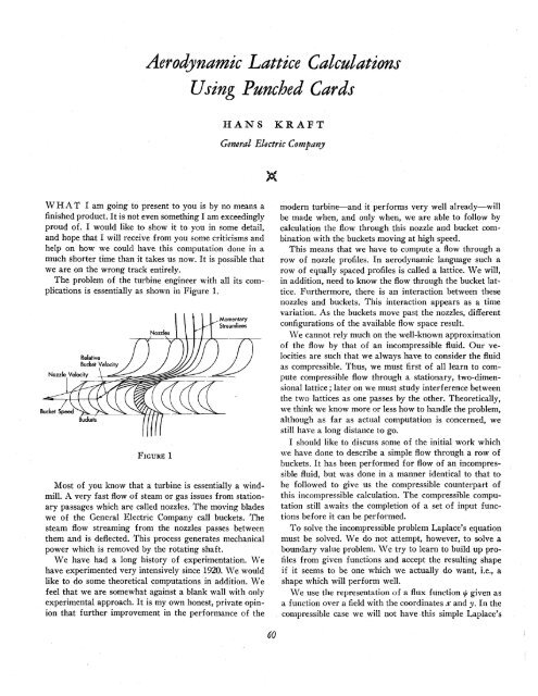
The problem of the turbine engineer with all its complications<br />
is essentially as shown in Figure 1.<br />
Nozzle Velocity<br />
Relative<br />
Bucket Velocity<br />
FIGURE 1<br />
HANS KRAFT<br />
General Electric Company<br />
Momentary<br />
Streamlines<br />
Most of you know that a turbine is essentially a windmill.<br />
A very fast flow .of steam or gas issues from stationary<br />
passages which are called nozzles. The moving blades<br />
we of the General Electric Company call buckets. The<br />
steam flow streaming from the nozzles passes between<br />
them and is deflected. This process generates mechanical<br />
power which is removed by the rotating shaft.<br />
We have had a long history of experimentation. We<br />
have experimented very intensively since 1920. We would<br />
like to do some theoretical computations in addition. We<br />
feel that we are somewhat against a blank wall with only<br />
experimental approach. It is my own honest, private opinion<br />
that further improvement in the performance of the<br />
60<br />
modern turbine-and it performs very well already-will<br />
be made when, and only when, we are able to follow by<br />
calculation the flow through this nozzle and bucket combination<br />
with the buckets moving at high speed.<br />
This means that we have to compute a flow through a<br />
row of nozzle profiles. In aerodynamic language such a<br />
row of equally spaced profiles is called a lattice. We will,<br />
in addition, need to kn.ow the flow through the bucket lattice.<br />
Furthermore, there is an interaction between these<br />
nozzles and buckets. This interaction appears as a time<br />
variation. As the buckets move past the nozzles, different<br />
configurations of the available flow space result.<br />
\Ve cannot rely much on the well-known approximati.on<br />
of the flow by that of an incompressible fluid. Our velocities<br />
are such that we always have to consider the fluid<br />
as compressible. Thus, we must first of all learn to compute<br />
compressible flow through a stationary, two-dimensionallattice<br />
; later on we must study interference between<br />
the two lattices as one passes by the other. Theoretically,<br />
we think We know more or less how to handle the problem,<br />
although as far as actual computation is c.oncerned, we<br />
still have a long distance to go.<br />
I should like to discuss some of the initial work which<br />
we have done to describe a simple flow through a row of<br />
buckets. It has been performed for flow of an incompressible<br />
fluid, but was done in a manner identical to that to<br />
be followed to give us the compressible counterpart of<br />
this incompressible calculation. The compressible computation<br />
still awaits the completion of a set .of input functions<br />
before it can be performed.<br />
To solve the incompressible problem Laplace's equation<br />
must be solved. We do not attempt, however, to solve a<br />
boundary value problem. \Ve try to learn to build up profiles<br />
from given functions and accept the resulting shape<br />
if it seems to be one which we actually do want, i.e., a<br />
shape which will perform well.<br />
We use the representation of a flux function t/t given as<br />
a function over a field with the coordinates..X' and y. In the<br />
compressible case we will not have this simple Laplace's


