PDF file - Facultatea de Chimie şi Inginerie Chimică
PDF file - Facultatea de Chimie şi Inginerie Chimică
PDF file - Facultatea de Chimie şi Inginerie Chimică

You also want an ePaper? Increase the reach of your titles
YUMPU automatically turns print PDFs into web optimized ePapers that Google loves.
R /(mol m -2 s -1 )<br />
0.06<br />
0.05<br />
0.04<br />
0.03<br />
0.02<br />
0.01<br />
0.00<br />
-0.01<br />
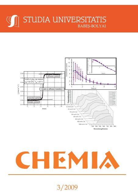
5.66% C2H6-airmixture p0 =100 kPa; Tw =487K<br />
induction period<br />
kinetic control<br />
kinetic to diffusion transition<br />
0 2 4 6 8 10<br />
time/s<br />
diffusion control<br />
Concentration (ng/ml)<br />
CHEMIA<br />
14<br />
12<br />
10<br />
3/2009<br />
8<br />
6<br />
4<br />
2<br />
0<br />
Concentration (ng/ml)<br />
10.0<br />
1.0<br />
0 4 8 12<br />
0.1<br />
Time (h)<br />
0 3 6 9 12<br />
Time (h)
ANUL LIV 2009<br />
S T U D I A<br />
UNIVERSITATIS BABEŞ-BOLYAI<br />
CHEMIA<br />
3<br />
Desktop Editing Office: 51 ST B.P. Has<strong>de</strong>u Street, Cluj-Napoca, Romania, Phone + 40 264-405352<br />
CUPRINS – CONTENT – SOMMAIRE – INHALT<br />
LIANA MUREŞAN, ALEXANDRA CSAVDÁRI, Professor Ioan Bâl<strong>de</strong>a<br />
at his 70’s Anniversary ..............................................................................5<br />
MARCELA ACHIM, DANA MUNTEAN, LAURIAN VLASE, IOAN BÂLDEA,<br />
DAN MIHU, SORIN E. LEUCUŢA, New LC/MS/MS Method for the<br />
Quantification of Phenytoin in Human Plasma ...................................... 7<br />
ECATERINA BICA, LAURA ELENA MUREŞAN, LUCIAN BARBU-<br />
TUDORAN, EMIL INDREA, IONEL CĂTĂLIN POPESCU,<br />
ELISABETH-JEANNE POPOVICI, Studies on WO3 Thin Films<br />
Prepared by Dip-Coating Method ........................................................ 15<br />
ADRIAN-IONUŢ CADIŞ, ADRIAN RAUL TOMŞA, ECATERINA BICA,<br />
LUCIAN BARBU-TUDORAN, LUMINIŢA SILAGHI-DUMITRESCU,<br />
ELISABETH-JEANNE POPOVICI, Preparation and Characterization<br />
of Manganese Doped Zinc Sulphi<strong>de</strong> Nanocrystalline Pow<strong>de</strong>rs<br />
With Luminescent Properties............................................................... 23<br />
COSMIN CĂŢĂNAŞ, MIHAI MOGOŞ, DANIEL HORVAT, JAKAB<br />
ENDRE, ELEONORA MARIA RUS, IULIU OVIDIU MARIAN,<br />
Electrical Characteristics of a Biobattery with Staphylococcus Aureus ..... 31
ANA-MARIA CORMOS, JOZSEF GASPAR, ANAMARIA PADUREAN,<br />
Mo<strong>de</strong>ling and Simulation of Carbon Dioxi<strong>de</strong> Absorption in<br />
Monoethanolamine in Packed Absorption Columns............................ 37<br />
EUGEN DARVASI, LADISLAU KÉKEDY-NAGY, Red Pepper Pow<strong>de</strong>r<br />
Color Measurement by Using an Integrating Sphere and Digital<br />
Image Processing................................................................................ 49<br />
VALENTINA R. DEJEU, BARABÁS RÉKA, POP ALEXANDRU,<br />
BOGYA ERZSÉBET SÁRA, PAUL-ŞERBAN AGACHI, Mathematical<br />
Mo<strong>de</strong>ling for the Crystallization Process of Hydroxyapatite<br />
Obtained by Precipitation in Aqueous Solution ................................... 61<br />
SILVIA LENUŢA DUNCA, MONICA KULCSAR, ANCA SILVESTRU,<br />
CRISTIAN SILVESTRU, COSTEL SÂRBU, Study of The<br />
Chromatographic Retention of Some New Organoselenium and<br />
Organotellurium Compounds Containing Intramolecular Interactions<br />
by HPTLC............................................................................................ 71<br />
NATHAN FLEURET, SEBASTIAN PAIC, GABRIELA NEMES,<br />
RALUCA SEPTELEAN, PETRONELA PETRAR, IOAN SILAGHI-<br />
DUMITRESCU, Lower Rim Silyl Substituted Calix[8]Arenes .............. 81<br />
OSSI HOROVITZ, MARIA TOMOAIA-COTIŞEL, CSABA RACZ,<br />
GHEORGHE TOMOAIA, LIVIU-DOREL BOBOŞ, AURORA<br />
MOCANU, The Interaction of Silver Nanoparticles with Lipoic Acid ....... 89<br />
FLORICA IMRE-LUCACI, SORIN-AUREL DORNEANU, PETRU ILEA,<br />
Optimisation of Copper Removal from Diluted Solutions .................... 97<br />
MELINDA-HAYDEE KOVACS, DUMITRU RISTOIU, SIDONIA VANCEA,<br />
LUMINITA SILAGHI-DUMITRESCU, Volatile Organic Disinfection<br />
by Products Determination in Distribution System from Cluj Napoca ... 107<br />
ANDRADA MĂICĂNEANU, COSMIN COTEŢ, VIRGINIA DANCIU,<br />
MARIA STANCA, Iron Doped Carbon Aerogel as Catalyst for<br />
Phenol Total Oxidation ...................................................................... 117<br />
ANDRADA MĂICĂNEANU, HOREA BEDELEAN, SILVIA BURCĂ , MARIA<br />
STANCA, Heavy Metal Ions Removal from Mo<strong>de</strong>l Wastewaters<br />
Using Oraşul Nou (Transilvania, Romania) Bentonite Sample.......... 127<br />
CRISTINA MIHALI, GABRIELA OPREA, ELENA CICAL, PVC Matrx<br />
Ionic - Surfactant Selective Electro<strong>de</strong>s Based on the Ionic Pair<br />
Tetra Alkyl-Ammonium –Laurylsulphate............................................ 141<br />
DAN MIHU, LAURIAN VLASE, SILVIA IMRE, CARMEN M. MIHU,<br />
MARCELA ACHIM, DANIELA LUCIA MUNTEAN, New LC/MS<br />
Method for Determination of Progesterone in Human Plasma for<br />
Therapeutic Drug Monitoring in Pregnancy and Gynecological<br />
Disor<strong>de</strong>rs ........................................................................................... 151
ANCA PETER, MONICA BAIA, FELICIA TODERAS, MIHAELA LAZAR,<br />
LUCIAN BARBU TUDORAN, VIRGINIA DANCIU, Photo-Catalysts<br />
Based on Gold - Titania Composites................................................. 161<br />
TÍMEA PERNYESZI, KRISZTINA HONFI, BORBALA BOROS, KATALIN<br />
TÁLOS, FERENC KILÁR, CORNELIA MAJDIK, Biosorption of Phenol<br />
from Aqueous Solutions by Fungal Biomass of Phanerochaete<br />
Chrysosporium .................................................................................. 173<br />
ANDREI ROTARU, MIHAI GOŞA, EUGEN SEGAL, Isoconversional<br />
Linear Integral Kinetics of the Non-Isothermal Evaporation of<br />
4-[(4-Chlorobenzyl)Oxy]-4’-Trifluoromethyl-Azobenzene .................. 185<br />
OCTAVIAN STAICU, VALENTIN MUNTEANU, DUMITRU OANCEA,<br />
Overall Kinetics for the Catalytic Ignition of Ethane-Air Mixtures<br />
on Platinum........................................................................................ 193<br />
MARIA ŞTEFAN, IOAN BÂLDEA, RODICA GRECU , EMIL INDREA,<br />
ELISABETH-JEANNE POPOVICI, Growth and Characterisation of<br />
Zinc-Cadmium Sulphi<strong>de</strong> Thin Films with Special Optical Properties .... 203<br />
MIHAELA-CLAUDIA TERTIŞ, FLORINA IONESCU, MARIA JITARU,<br />
Equilibrium Study on Adsorption Processes of 4-Nitrophenol and<br />
2, 6-Dinitrophenol Onto Granular Activated Carbon.......................... 213<br />
CAMELIA VARGA, MONICA MARIAN, ANCA PETER, DELIA BOLTEA,<br />
LEONARD MIHALY-COZMUTA, EUGEN NOUR, Strategies of<br />
Heavy Metal Uptake by Phaseolus Vulgaris Seeds Growing in<br />
Metalliferous and Non-Metalliferous Areas........................................ 223<br />
SIMONA VARVARA, MARIA POPA, LIANA MARIA MURESAN,<br />
Corrosion Inhibition of Bronze by Amino Acids in Aqueous Acidic<br />
Solutions............................................................................................ 235<br />
LIDIA VARVARI, SORIN-AUREL DORNEANU, IONEL CĂTĂLIN<br />
POPESCU, Potassium-Selective Electro<strong>de</strong> Based on a CALIX[6]<br />
Arenic Ester (C6ES6) ........................................................................ 247<br />
CODRUTA VARODI, DELIA GLIGOR, LEVENTE ABODI, LIANA<br />
MARIA MURESAN, Comparative Study of Carbon Paste<br />
Electro<strong>de</strong>s Modified with Methylene Blue and Methylene Green<br />
Adsorbed on Zeolite as Amperometric Sensors for H2O2 Detection ..... 255<br />
LAURIAN VLASE, DANA MUNTEAN, ADINA POPA, MARIA NEAG,<br />
IOAN BÂLDEA, MARCELA ACHIM, SORIN E. LEUCUŢA,<br />
Pharmacokinetic Interaction between Ivabradine and Ciprofloxacine<br />
in Healthy Volunteers ........................................................................ 265
Studia Universitatis Babes-Bolyai Chemia has been selected for coverage<br />
in Thomson Reuters products and custom information services. Beginning<br />
with V. 53 (1) 2008, this publication is in<strong>de</strong>xed and abstracted in the following:<br />
• Science Citation In<strong>de</strong>x Expan<strong>de</strong>d (also known as SciSearch®)<br />
• Chemistry Citation In<strong>de</strong>x®<br />
• Journal Citation Reports/Science Edition
Professor Ioan Bâl<strong>de</strong>a at his 70’s Anniversary<br />
Brilliant teacher and warm colleague,<br />
Professor Ioan Bâl<strong>de</strong>a was born on the 21 st<br />
of October 1939. Still active, he <strong>de</strong>dicates<br />
himself to science and teaching after<br />
graduating Babeş-Bolyai University as a<br />
chemist in 1962. Well-known in the aca<strong>de</strong>mic<br />
community as one of the top kineticists<br />
of the country, his 70’s anniversary<br />
finds him with unaltered optimism and<br />
creativeness.<br />
Beginning immediately after graduation<br />
as a teaching assistant, his aca<strong>de</strong>mic<br />
carrier unfol<strong>de</strong>d rigorously step by step, while<br />
obtaining his PhD in 1969. As an appointed<br />
lecturer (1971), associated professor (1990)<br />
and full professor (1993), his work continuously<br />
contributed to the <strong>de</strong>velopment and growth of the Department of Physical<br />
Chemistry.<br />
Besi<strong>de</strong>s over 120 various scientific papers, Professor Ioan Bâl<strong>de</strong>a also<br />
published 4 books as a single author and contributed to 2 others. These<br />
summarize his prodigious experience in chemical kinetics of homogeneous<br />
redox and organic reactions, characterization of short-life chemical complexes,<br />
mo<strong>de</strong>ling of complex processes, <strong>de</strong>sign and reactor engineering as well as<br />
kinetic methods of analysis. This valuable and diverse knowledge was shared<br />
with the young scientists he tutored during their PhD scholarships. It also<br />
contributed both to solving of over 50 contracts and putting forward of 4 patents<br />
for the Romanian chemical industry. A production line for ethyl acetate was<br />
based on his <strong>de</strong>signs and functioned till the early 90’s at the plant in<br />
Craiova. The 12 research Grants he coordinated (among these, one financed<br />
by the World Bank) substantially contributed to the <strong>de</strong>velopment of Chemical<br />
Kinetics and General Physical Chemistry at the Babeş-Bolyai University.<br />
While always en<strong>de</strong>avoring on sharing and passing over his knowledge<br />
to the young generations, Professor Bâl<strong>de</strong>a wrote or collaborated to the<br />
publication of 8 manuals of Physical as well as General Chemistry. The stu<strong>de</strong>nts<br />
highly appreciated the funny and nonconformist explanations; the examples<br />
illustrating daily life ma<strong>de</strong> his lectures colorful and easy to un<strong>de</strong>rstand. The<br />
approximately 100 graduate and postgraduate thesis coordinated by the<br />
Professor stand proof for this fact.
6<br />
PROFESSOR IOAN BÂLDEA AT HIS 70’S ANNIVERSARY<br />
Also beloved and highly regar<strong>de</strong>d by his colleagues, Professor Ioan<br />
Bâl<strong>de</strong>a was elected for nearly 10 years as Head of the Department of Physical<br />
Chemistry and represented for 23 years the same Department in the Faculty’s<br />
Council. He was also the local coordinator of the CEEPUS aca<strong>de</strong>mic exchange<br />
Program for 8 years. The vast experience allowed the Professor to manage the<br />
Program of didactic personnel improvement for 8 years and to be a referee<br />
for various scientific publications, grants and events.<br />
This issue of Studia Universitas Babeş-Bolyai, Seria Chemia reflects<br />
the tight professional relationships Professor Ioan Bâl<strong>de</strong>a has build within<br />
the aca<strong>de</strong>mic community of Romania. Teachers and researchers from the<br />
University of Bucharest, Baia-Mare or Iuliu HaŃieganu University of Medicine<br />
from Cluj-Napoca also contributed to this volume.<br />
Now, at his 70’s anniversary, we – the colleagues of the Department<br />
of Physical Chemistry – as well as all the colleagues and researchers of the<br />
Faculty of Chemistry of the Babeş-Bolyai University, along with the Editorial<br />
Board, wish Professor Ioan Bâl<strong>de</strong>a health in the many years to come, as well<br />
as the spice of current valuable scientific activity.<br />
Volum Editors<br />
Liana Mureşan<br />
Alexandra Csavdári
STUDIA UNIVERSITATIS BABEŞ-BOLYAI, CHEMIA, LIV, 3, 2009<br />
NEW LC/MS/MS METHOD FOR THE QUANTIFICATION<br />
OF PHENYTOIN IN HUMAN PLASMA<br />
MARCELA ACHIM a , DANA MUNTEAN a , LAURIAN VLASE a ,<br />
IOAN BÂLDEA b , DAN MIHU c , SORIN E. LEUCUŢA a<br />
ABSTRACT. A simple, reversed-phase high performance liquid chromatography<br />
method with mass spectrometric <strong>de</strong>tection (HPLC-MS/MS) was <strong>de</strong>veloped<br />
for <strong>de</strong>termination of an antiepileptic drug, phenytoin, in human plasma. The<br />
procedure involves a simple extraction step by mixing 0.2 ml plasma with<br />
0.6 ml methanol. After centrifugation, 1 µl of the supernatant was injected onto<br />
a Zorbax SB-C18 100 mm x 3 mm, 3.5 µm column, and eluted with a mobile<br />
phase consisting in a mixture of water containing 2 mM ammonium acetate<br />
and methanol 50:50 (v/v). Detection was in MRM mo<strong>de</strong>, using an electrospray<br />
positive ionization. The ion transition monitored was 253.1→(182.1+225.1). The<br />
method was evaluated in terms of linearity (between 2.0 µg/ml to 80.0 µg/ml),<br />
accuracy, precision, recovery, sensitivity. The lower limit of quantification<br />
was established at 2.0 µg/ml. The simple extraction procedure and short<br />
chromatographic runtime make the method suitable for therapeutic drug<br />
monitoring studies.<br />
Keywords: phenytoin, HPLC-MS/MS, human plasma<br />
INTRODUCTION<br />
Phenytoin (Figure 1) is wi<strong>de</strong>ly used in the treatment of epilepsy and is<br />
effective against all types of seisures. No drug has greater need for therapeutic<br />
drug concentration monitoring and individualized dosing than phenytoin. A good<br />
correlation usually is observed between the total concentration of phanytoin<br />
in plasma and the clinical effect. Therapeutic concentration of phenytoin is<br />
above 10 µg/ml [1]. Enzyme induction by phenytoin is well documented, even<br />
auto-induction by phenytoin should be consi<strong>de</strong>red during the treatment with<br />
phenytoin [2].<br />
a<br />
University of Medicine and Pharmacy “Iuliu Haţieganu”, Faculty of Pharmacy, Emil Isac 13,<br />
RO-400023 Cluj-Napoca, Romania, dana@tbs.ubbcluj.ro<br />
b<br />
Babeş-Bolyai” University, Faculty of Chemistry and Chemical Engineering, Arany Janos 11,<br />
RO-400028 Cluj-Napoca, Romania<br />
c<br />
University of Medicine and Pharmacy “Iuliu Haţieganu”, Faculty of Medicine, Emil Isac 13,<br />
RO-400023 Cluj-Napoca, Romania
MARCELA ACHIM, DANA MUNTEAN, LAURIAN VLASE, IOAN BÂLDEA, DAN MIHU, SORIN E. LEUCUŢA<br />
Plasma concentration monitoring is wi<strong>de</strong>ly used for the clinical management<br />
of epileptic patients receiving phenytoin [3]. To minimize toxicity, monitoring of<br />
plasma anticonvulsant levels is a part of the routine management of patients in<br />
many clinics. To the best of our knowledge, almost all of the methods that<br />
were applied for <strong>de</strong>termination of antieplileptic drugs in biological media are<br />
often chromatography, electrophoresis and immunoassay techniques [4,5].<br />
The aim of the present study was to <strong>de</strong>velop a fast LC-MS/MS method,<br />
able to quantify phenytoin in human plasma after a simple sample preparation<br />
by protein precipitation. The proposed method proved to be accurate and <strong>de</strong>spite<br />
of very simple sample preparation, showed high sensitivity.<br />
RESULTS AND DISCUSSION<br />
8<br />
C6H5<br />
C6H5<br />
O<br />
H<br />
N<br />
NH<br />
Figure 1. Molecular structure of phenytoin<br />
Figure 2 shows representative chromatograms of drug-free (blank)<br />
human plasma and a sample containing 2.0 µg/ml phenytoin (LOQ). No<br />
significant interference at the retention time of phenytoin (1.6 min) was<br />
observed, due to the specificity of the selected signal (Figure 3).<br />
Intens.<br />
6000<br />
4000<br />
2000<br />
0<br />
6000<br />
4000<br />
2000<br />
0<br />
CAL2__01.D: EIC 182.1; 225.1 ±MS2(253), Smoothed (0.3,1, GA)<br />
CAL2__02.D: EIC 182.1; 225.1 ±MS2(253), Smoothed (0.3,1, GA)<br />
0.2 0.4 0.6 0.8 1.0 1.2 1.4 1.6 Time [min]<br />
Figure 2. Chromatograms of a drug-free plasma sample (up) and LOQ plasma<br />
standard with 2.0 µg/ml phenytoin (down)<br />
O
NEW LC/MS/MS METHOD FOR THE QUANTIFICATION OF PHENYTOIN IN HUMAN PLASMA<br />
Intens.<br />
x105<br />
0.6<br />
0.4<br />
0.2<br />
0.0<br />
x104<br />
2.0<br />
1.5<br />
1.0<br />
0.5<br />
0.0<br />
182.1<br />
sp____02.d: +MS2(253.2), 540.8min (#2)<br />
225.1<br />
253.1<br />
sp____03.d: +MS2(253.2), 541.5min (#2)<br />
160 180 200 220 240 260 280 m/z<br />
Figure 3. Mass spectra of phenytoin. Full-scan spectrum (up) and<br />
MS/MS spectrum (down). The sum of ions with m/z 182.1 and 225.1<br />
was used for quantification<br />
The analyte <strong>de</strong>tection was ma<strong>de</strong> in MRM mo<strong>de</strong>, the ion transition<br />
monitored was m/z 253.1→(m/z 182.1 + m/z 225.1). This way, the <strong>de</strong>tection is<br />
more sensitive than in case based only on ion m/z 253.1 (Figure 3).<br />
The analyte carryover was verified using a blank injection ma<strong>de</strong> right<br />
after an injection of the most elevated concentration level from calibration<br />
curve. No interference at retention time of analyte due to carryover was<br />
observed.<br />
The mean calibration curve y = a(±S.D.)x + b(±S.D.), with S.D. standard<br />
<strong>de</strong>viation, was: y = (59590.4±1971.9)x – (10490.5±2501.6), N = 8 calibration<br />
points, n = 5 <strong>de</strong>terminations for each calibration point. The residuals had no<br />
ten<strong>de</strong>ncy of variation with concentration. The applied calibration curve mo<strong>de</strong>l<br />
proved to be accurate over the concentration range 2 – 80 µg/ml, with a<br />
correlation coefficient grater than 0.998 (Figure 4).<br />
The intra-day precision was <strong>de</strong>termined from replicate analysis of<br />
samples containing phanytoin at four different concentrations covering the low,<br />
medium and higher ranges of calibration curve (Table 1), in good agreement to<br />
international regulations regarding bioanalytical methods validation [6-8].<br />
The intra-day precision and accuracy ranged from 1.9% to 9.5% and 3.7%<br />
to 10% respectively.<br />
9
MARCELA ACHIM, DANA MUNTEAN, LAURIAN VLASE, IOAN BÂLDEA, DAN MIHU, SORIN E. LEUCUŢA<br />
10<br />
Figure 4. Calibration curve for phenytoin<br />
Table 1. Intra-day precision, accuracy and recovery for phenytoin (n = 5)<br />
cnominal<br />
(µg/ml)<br />
Mean cfound<br />
(µg/ml) (± S.D.)<br />
C.V. % Bias %<br />
Recovery %<br />
(± S.D.)<br />
2.0 2.07 (0.2) 9.5 3.7 106.5 (10.5)<br />
5.0 5.50 (0.10) 1.9 10.0 100.3 (1.9)<br />
32.0 34.87 (1.94) 5.6 9.0 102.4 (5.7)<br />
64.0 67.60 (3.74) 5.5 5.6 101.1 (5.6)<br />
The intra-day precision and accuracy were <strong>de</strong>termined by analyzing<br />
in five different days samples that have the same concentration, at lower,<br />
medium and higher levels from calibration curve. The precision ranged from<br />
3.5% to 10.1% and accuracy from 1.5% to 7.2 % (Table 2):<br />
Table 2. Inter-day precision, accuracy and recovery for phenytoin (n = 5)<br />
cnominal<br />
(µg/ml)<br />
Mean cfound<br />
(µg/ml) (± S.D.)<br />
C.V. % Bias %<br />
Recovery %<br />
(± S.D.)<br />
2.0 2.03 (0.20) 10.1 1.5 121.1 (35.3)<br />
5.0 5.36 (0.21) 4.0 7.2 97.3 (9.1)<br />
32.0 33.10 (1.16) 3.5 3.4 101.4 (5.6)<br />
64.0 66.32 (2.87) 4.3 3.6 99.1 (4.6)
NEW LC/MS/MS METHOD FOR THE QUANTIFICATION OF PHENYTOIN IN HUMAN PLASMA<br />
Un<strong>de</strong>r the experimental conditions used, the lower limit of quantification<br />
(LOQ) was of 2 µg/ml phenytoin. LOQ is the lowest amount of analyte<br />
which can be measured with accuracy and precision less than 20%.<br />
CONCLUSIONS<br />
A simple, sensitive, accurate and precise HPLC/MS/MS method for<br />
<strong>de</strong>termination of phenytoin in human plasma using a simple single-step<br />
extraction procedure is reported. Another advantage of the method is the<br />
short chromatographic runtime of only 2.1 min. The method is suitable for<br />
therapeutic drug monitoring studies and can also be used for pharmacokinetic<br />
studies conducted on healthy volunteers [9-13].<br />
EXPERIMENTAL SECTION<br />
Reagents<br />
Phenytoin, methanol, ammonium acetate, were purchased from Merck<br />
(Merck KgaA, Darmstadt, Germany). Solvents used were HPLC gra<strong>de</strong> and<br />
all other chemicals were of analytical gra<strong>de</strong>. Distilled, <strong>de</strong>ionised water was<br />
produced by a Direct Q-5 Millipore (Millipore SA, Molsheim, France) water<br />
system. The drug-free human plasma was supplied by the Local Bleeding<br />
Centre Cluj-Napoca, Romania.<br />
Preparation of standard solutions<br />
A stock solution containing 10 mg/ml phenytoin was prepared in<br />
methanol. A working solution of 200 µg/ml was prepared by diluting the<br />
appropriate volume of stock solution with plasma. Than this was used to<br />
spike different volumes of drug-free plasma, providing finally eight plasma<br />
standards with concentration between 2.0 and 80.0 µg/ml. Quality control<br />
samples (QC) of 5.0, 32.0, and 64.0 µg/ml were prepared by diluting specific<br />
volumes of working solution with plasma and were used to evaluate precision<br />
and accuracy of the method.<br />
Chromatographic and mass spectrometry systems and conditions<br />
The HPLC system was an 1100 series mo<strong>de</strong>l (Agilent Technologies)<br />
consisted in a binary pump, an in-line <strong>de</strong>gasser, an autosampler, a column<br />
thermostat and an Ion Trap VL mass spectrometer <strong>de</strong>tector (Bruckner Daltonics<br />
GmbH, Germany). Chromatograms were processed using QuantAnalysis<br />
Software. The <strong>de</strong>tection of phenytoin was in MRM (MS/MS) mo<strong>de</strong>, using an<br />
electrospray positive ionization (ESI positive). The ion transitions monitored<br />
was: m/z 253.1→(m/z 182.1 + m/z 225.1). Chromatographic separation was<br />
performed at 45ºC on a Zorbax SB-C18 100 mm x 3 mm, 3.5 µm column<br />
(Agilent Technologies), protected by an inline filter.<br />
11
MARCELA ACHIM, DANA MUNTEAN, LAURIAN VLASE, IOAN BÂLDEA, DAN MIHU, SORIN E. LEUCUŢA<br />
Mobile phase<br />
The mobile phase consisted in a mixture of water containing 2 mM<br />
ammonium acetate and methanol (50:50 v/v). It was always freshly prepared<br />
and was <strong>de</strong>gassed before elution for 10 min in am Elma Transsonic 700/H<br />
(Singen, Germany) ultrasonic bath. The pump <strong>de</strong>livered the mobile phase at a<br />
flow rate of 1 ml/min.<br />
Sample preparation<br />
Plasma samples were prepared as follows in or<strong>de</strong>r to be<br />
chromatographically analyzed: in an Eppendorf tube (max 1.5 ml), 0.2 ml<br />
plasma and 0.6 ml methanol were ad<strong>de</strong>d. The tube was vortex-mixed for 10 s<br />
(Vortex Genie 2, Scientific Industries) and centrifuged for 6 min at 5000 rpm<br />
(2-16 Sartorius centrifuge, Ostero<strong>de</strong> am Harz, Germany). The supernatant was<br />
transferred to an autosampler vial and 1 µl was injected into the HPLC system.<br />
Validation<br />
As a first step of method validation [6-8], specificity was verified<br />
using six different plasma blanks obtained from healthy volunteers who had<br />
not previously taken any medication.<br />
The concentration of the analyte was <strong>de</strong>termined automatically by the<br />
instrument data system. The calibration curve mo<strong>de</strong>l was y = ax + b, weight<br />
1/y linear response, where y-peak area and x-concentration. Distribution of the<br />
residuals (% difference of the back-calculated concentration from the nominal<br />
concentration) was investigated. The calibration mo<strong>de</strong>l was accepted, if the<br />
residuals were within ±20% at the lower limit of quantification (LOQ) and<br />
within ±15% at all other calibration levels and at least 2/3 of the standards<br />
meet this criterion, including highest and lowest calibration levels.<br />
The intra-day and inter-day precision (expressed as coefficient of<br />
variation, CV%) and accuracy (expressed as relative difference between<br />
obtained and theoretical concentration, bias%) of the assay procedure were<br />
<strong>de</strong>termined by analysing on the same day five different samples at each of<br />
the lower (5.0 µg/ml), medium (32.0 µg/ml) and higher (64.0 µg/ml) levels of<br />
the consi<strong>de</strong>red concentration range and one different sample of each at five<br />
different occasions, respectively.<br />
The recovery of phenytoin was analyzed at each of the three<br />
concentration levels mentioned above, e.g. lower, medium and higher level,<br />
and also at the quantification limit, by comparing the peack area response<br />
of spiked plasma samples with the response of standards prepared in water<br />
with the same concentration of ivabradine as the plasma samples, all these<br />
prepared as stated in section “Sample preparation”.<br />
ACKNOWLEDGMENTS<br />
This work was supported by Grant CEEX-ET co<strong>de</strong> 121, contract no.<br />
5860/2006, financed by CNCSIS Romania.<br />
12
NEW LC/MS/MS METHOD FOR THE QUANTIFICATION OF PHENYTOIN IN HUMAN PLASMA<br />
REFERENCES<br />
1. Z. Rezaei, B. Hemmateenejab, S. Khabnadi<strong>de</strong>h, M. Gorgin, Talanta, 2005, 65, 21.<br />
2. M. Cheety, R. Miller, M. A. Seymour, Ther. Drug Monit., 1998, 20, 60.<br />
3. K. M. Patil, S. L. Bodhankar, J. Pharm. Biomed. Analysis, 2005, 39, 181.<br />
4. D. J. Speed, S. J. Dickson, E. R. Cairus, N. D. Kim, J. Anal. Toxicol., 2000, 24, 685.<br />
5. M. E. Queiroz, S. M. Silvia, D. Carralho, F. M. Lancas, J. Chroma. Sci., 2002,<br />
40, 219.<br />
6. The European Agency for the Evaluation of Medicinal Products. Note for Guidance<br />
on the Investigation of Bioavailability and Bioequivalence, London, UK, 2001<br />
(CPMP/EWP/QWP/1401/98).<br />
7. U. S. Department of Health and Human Services, Food and Drug Administration,<br />
Center for Drug Evaluation and Research. Guidance for Industry. Bioavailability<br />
and Bioequivalence Studies for Orally Administrated Drug Products – General<br />
Consi<strong>de</strong>rations, Rockville, USA, 2003, http://www.fda.gov/c<strong>de</strong>r/guidance/in<strong>de</strong>x.htm.<br />
8. U. S. Department of Health and Human Services, Food and Drug Administration,<br />
Guidance for Industry – Bioanalytical Method Validation, 2001.<br />
9. L. Vlase L, S. E. Leucuta, S. Imre, Talanta, 2008, 75, 1104.<br />
10. L. Vlase, A. Leucuta, D. Farcau D, M. Nanulescu, Biopharma. Drug Dispos., 2006,<br />
27, 285.<br />
11. L. Vlase, S. Imre, D. Muntean, S. E. Leucuta, J.Pharma. Biomed. Analysis, 2007,<br />
44(3), 652.<br />
12. L. Vlase, D. Muntean, S. E. Leucuta, I. Bal<strong>de</strong>a, Studia Univ. Babes-Bolyai Chemia,<br />
2009, 54, 43.<br />
13. A. Butnariu, D. S. Popa, L. Vlase, M. Andreica, D. Muntean, S. E. Leucuta, Revista<br />
Romana De Medicina De Laborator, 2009, 15, 7.<br />
13
STUDIA UNIVERSITATIS BABEŞ-BOLYAI, CHEMIA, LIV, 3, 2009<br />
STUDIES ON WO3 THIN FILMS PREPARED BY<br />
DIP-COATING METHOD<br />
ECATERINA BICA a,b , LAURA ELENA MUREŞAN a , LUCIAN BARBU-<br />
TUDORAN c , EMIL INDREA d , IONEL CĂTĂLIN POPESCU b AND<br />
ELISABETH-JEANNE POPOVICI a<br />
ABSTRACT. WO3 films obtained by dip-coating technique were investigated<br />
to evi<strong>de</strong>nce the properties of tungsten trioxi<strong>de</strong> films for water splitting applications.<br />
The <strong>de</strong>position solution containing peroxo-tungstic acid was prepared by<br />
sol-gel method. The films were <strong>de</strong>posited on conductive glass substrates and<br />
were annealed at 250-550 0 C. The properties of WO3 films were investigated<br />
by UV-Vis Spectroscopy, X-Ray diffraction (XRD) and Scanning Electron<br />
Microscopy (SEM).<br />
Keywords: Tungsten trioxi<strong>de</strong> films; ITO support; Dip-coating.<br />
INTRODUCTION<br />
Tungsten oxi<strong>de</strong> (WO3) is a wi<strong>de</strong> – band gap semiconductor of great<br />
interest because of its applications in optoelectronics, catalysis and environmental<br />
engineering [1-3]. On the other hand, it was <strong>de</strong>monstrated that WO3 thin films<br />
exhibits chemical sensing properties such as H2S, NOx, [4-7]. Moreover, WO3<br />
thin films electro<strong>de</strong>s are reversible and have fast electrochromic properties [8].<br />
Tungsten oxi<strong>de</strong> films can be synthesized by several physical and<br />
chemical routes such as sputtering [9], acid precipitation method [10] and<br />
sol-gel processing [11-14].<br />
Application of tungsten trioxi<strong>de</strong> (WO3) thin films strongly <strong>de</strong>pends on<br />
morpho-structural characteristics that are regulated during the synthesis.<br />
The aim of this study is to obtain high quality WO3 thin films for photocatalysis<br />
and water splitting applications. The performed study presents the<br />
influence of some preparative conditions on the morpho-structural characteristics<br />
a<br />
Babeş-Bolyai University, “Raluca Ripan” Institute for Research in Chemistry, Fantanele 30,<br />
Cluj-Napoca, Romania, ebica@chem.ubbcluj.ro<br />
b<br />
Babeş-Bolyai University, Faculty of Chemistry and Chemical Engineering, Arany Janos 11,<br />
Cluj-Napoca, Romania<br />
c<br />
Babeş-Bolyai University, Electronic Microscopy Centre, Clinicilor 5-7, Cluj-Napoca, Romania<br />
d<br />
National Institute for R&D of Isotopic and Molecular Technologies, Donath 30, Cluj-Napoca,<br />
Romania
16<br />
E. BICA, L.E. MUREŞAN, L. BARBU-TUDORAN, E. INDREA, I.C. POPESCU, E.-J. POPOVICI<br />
of WO3 films, and put in evi<strong>de</strong>nce that the quality of the dip-coating solution<br />
and the thermal treatment play an important role on the properties of conductive<br />
glass supported WO3 films.<br />
RESULTS AND DISCUSSIONS<br />
WO3/ITO/Glass/WO3 heterostructures containing tungsten oxi<strong>de</strong> thin<br />
films were obtained using the dip-coating method, from peroxo-tungstic acid<br />
sol. The multilayer technique was used to prepare films with variable thickness<br />
whereas the thermal treatment was performed at 250 - 550°C (Table 1).<br />
Film thickness varies between 35 and 135 nm, in parallel with the number of<br />
dip coating <strong>de</strong>position cycles; it seems that the thickness is not influenced<br />
by the annealing regime.<br />
Table 1. Synthesis conditions of WO3 thin films prepared from<br />
peroxo-tungstic acid sol (dip-coating method)<br />
Sample co<strong>de</strong> Thermal<br />
treatment<br />
( 0 C)<br />
Number of<br />
layers<br />
WO3 weight<br />
(g)<br />
Film thickness<br />
(nm)<br />
R4 I1 350 1 0.55 x 10 -3<br />
35<br />
R4 I2 350 2 0.94 x 10 -3 60<br />
R4 I3 350 3 1.62 x 10 -3 95<br />
R4 I4 350 4 1.97 x 10 -3 125<br />
R4 I5 350 5 2.20x 10 -3 135<br />
R3.1 I2 250 1 0.30 x 10 -3 20<br />
R3.1 I3 350 1 0.56 x 10 -3 35<br />
R3.1 I4 550 1 0.50 x 10 -3 35<br />
In or<strong>de</strong>r to establish the optimal thermal treatment regime for WO3 thin<br />
films, the peroxo-tungstic acid (PTA) precursor was investigated by thermal<br />
analysis.<br />
Figure 1. TGA and DTG curves of<br />
PTA precursor.<br />
Figure 2. FT-IR spectrum of<br />
PTA precursor.
STUDIES ON WO3 THIN FILMS PREPARED BY DIP-COATING METHOD<br />
The TGA and DTG curves of PTA precursor indicate three most<br />
important weight loss steps i.e. (1) -14.92% at 20-200°C (removal of physical<br />
adsorbed water and alcohol); (2) -3.35% at 235-345 °C (removal of H2O2, i.e.<br />
peroxo-tungstic acid <strong>de</strong>composition) and (3) -1.05% at 345-405 °C (removal of<br />
chemically bon<strong>de</strong>d water i.e. tungstic acid <strong>de</strong>composition) (Fig.1).The weight<br />
loss steps are accompanied by weak endo- and exo- thermal effects.<br />
The FT-IR spectrum of the precursor pow<strong>de</strong>r (that corresponds to<br />
the as- <strong>de</strong>posited WO3 film), illustrates the hydrated and the hydroxilated<br />
nature of the WO3 <strong>de</strong>posit (Figure 2). Water presence is signalled by the<br />
3418 cm -1 {ν(OH)} and 1617 cm -1 {δ(HOH)} bands. Because the ν(OH) appears<br />
as a single featureless band, it is difficult to isolate the in<strong>de</strong>pen<strong>de</strong>nt contributions<br />
from structural water, hydroxyl groups, hydrogen bon<strong>de</strong>d and adsorbed species.<br />
Despite the complexity of the W-O stretching bands region (400-1000cm -1 ), it<br />
gives important information about the precursor. Besi<strong>de</strong>s the specific ν(W-Ointra-W)<br />
and ν(W-Ointer-W) bridging stretches ( 863-823 cm -1 and 687 -625 cm -1 ), the<br />
stretching vibrations of W(O2) and W-O could be noticed (959 cm -1 and<br />
553 cm -1 ), thus indicating the formation of [(O2)2W(O).O.W(O)(O2)2] 2- complex<br />
associated with the peroxo-tungstic acid [15-17].<br />
The optical properties of WO3 films were evaluated from UV-Vis<br />
transmission (Figure 3) and reflection (Figure 4) spectra.<br />
a. b.<br />
Figure 3. Transmission spectra of WO3 films obtained in different conditions:<br />
a) multilayer films treated at 350°C; b) monolayer films annealed at 250 – 550°C.<br />
The monolayer WO3 film (R4I1) shows an almost constant transmittance<br />
of about 80% on the entire visible domain. As expected, the multilayer films<br />
R4I2, R4I3, R4I4 and R4I5 have a lower transmittance (50 -80 %) as compared<br />
with the monolayer heterostructures. The absorption edge shifts from 300 nm<br />
to 315 nm as the film thickness increases (Figure 3a).<br />
17
18<br />
E. BICA, L.E. MUREŞAN, L. BARBU-TUDORAN, E. INDREA, I.C. POPESCU, E.-J. POPOVICI<br />
The thermal treatment <strong>de</strong>termines the <strong>de</strong>creases of the transmittance,<br />
in parallel with the temperature increase (Figure 3b). The thermal treatment<br />
also produces the color change of transparent films from colorless to yellowpale,<br />
thus suggesting some morpho-structural variation.<br />
Figure 4. Reflectance spectra for the multilayer WO3 film (R4I5)<br />
measured on ITO face.<br />
The specular reflectance (8 0 -0 0 ) spectrum is obtained by the difference<br />
between the total reflectance (8 0 ) and diffuse reflectance (0 0 ) spectra. The<br />
reflection maximum is situated in the blue range of the spectral domain.<br />
In or<strong>de</strong>r to <strong>de</strong>termine the optical energy band gap of WO3 films, the<br />
Bar<strong>de</strong>en equation [18] was used:<br />
r<br />
( α hν ) = A(<br />
hν<br />
− Eg<br />
)<br />
(1)<br />
where: α is the absorption coefficient, Eg is the energy band gap of the<br />
semiconductor, h is the Plank’s constant, A is a parameter that <strong>de</strong>pends<br />
on the transition probability and r is a number that characterises the transition<br />
process. Depending on the semiconductor type, r values could be: r =2 and<br />
2/3 for direct allowed and forbid<strong>de</strong>n transitions, respectively, and r=1/2 and<br />
1/3 for indirect allowed and forbid<strong>de</strong>n transitions, respectively [18]. The<br />
absorption coefficient α was calculated using the formula (2):<br />
exp( − α d ) = T<br />
(2)<br />
where:<br />
d is the film thickness (see table 1), and T is the measured transmittance [19].
STUDIES ON WO3 THIN FILMS PREPARED BY DIP-COATING METHOD<br />
From the transmittance spectra of WO3 films (calculated without<br />
substrate), the band gap energy (Eg) was evaluated using the Tauc plot’s,<br />
by extrapolation of the straight line in the plot (αhν) 1/2 vs hν (Figure 5).<br />
The <strong>de</strong>termined band gap of dip-coated WO3 films varies between<br />
2.9 and 3.2eV, in agreement with the literature data [20, 21]. The plot feature<br />
illustrates that the as obtained WO3 films behaves as an indirect semiconductor<br />
between about 3.3 and 4.0 eV [20].<br />
Figure 5. Plot of (αhν) 1/2 vs hν for WO3 films.<br />
The X-ray diffraction indicates that peroxotungstic acid precursor<br />
is amorphous, whereas the WO3 films <strong>de</strong>posited on conductive glass are<br />
crystallized (Figure 6).<br />
Figure 6. XRD patterns for PTA precursor and the corresponding<br />
heterostructure WO3/ITO/Glass/WO3 (film R4I5).<br />
19
20<br />
E. BICA, L.E. MUREŞAN, L. BARBU-TUDORAN, E. INDREA, I.C. POPESCU, E.-J. POPOVICI<br />
The XRD pattern contains the characteristic diffraction lines of the<br />
conductive substrate i<strong>de</strong>ntified as being cubic SnO2 (JCPDS 33-1374) and<br />
the diffraction lines of monoclinic WO3 (JCPDS 72-0677). One can be noted<br />
that, due to the crystalline structure of the substrate, the growth of WO3 films<br />
seams to be oriented alongsi<strong>de</strong> the (200) reflection plane.<br />
The SEM images illustrate that WO3 film consists on nano-metric<br />
particles that creates a homogeneous surface (Figure 7). A small ten<strong>de</strong>ncy<br />
toward the increase of cracks number with the number of layers could be<br />
noticed. More than that, the increase of the annealing temperature from<br />
350 0 C to 550 0 C, leads to the formation of larger crakes in the WO3 film.<br />
a b<br />
c<br />
Figure 7. SEM images of WO3 film surface: (a) one layer (350°C)<br />
(b) five layers (350 0 C) and (c) one layer (550 0 C).<br />
CONCLUSIONS<br />
Homogeneous and adherent WO3 thin films were obtained by dip<br />
coating technique, on conductive glass substrates from aqueous solution of<br />
peroxotungstic acid obtained by dissolving fresh prepared tungstic acid into<br />
hydrogen peroxi<strong>de</strong> solution. Film thickness increases from ~35 to 135 nm<br />
as the number of dip coating <strong>de</strong>position cycles increases.
STUDIES ON WO3 THIN FILMS PREPARED BY DIP-COATING METHOD<br />
Thermal analysis and FT-IR spectroscopy suggest that the precursor<br />
isolated from the colloidal dip-coating solution, corresponds to peroxotungstic<br />
acid.<br />
The optical transmittance of WO3 films is influenced by the number<br />
of layers. In this respect, the WO3/ITO/Glass/WO3 monolayer has a good<br />
transmittance between 450-1000 nm and it <strong>de</strong>creases as the film thickness<br />
increases. The thermal treatment <strong>de</strong>teriorates the transmission of WO3 films.<br />
The calculated values of the optical band gap energy (Eg) vary between 2.9 and<br />
3.2eV, in accordance with the literature data. The reflectance of the as obtained<br />
WO3 films is dominant in the blue domain of visible spectra.<br />
SEM images put in evi<strong>de</strong>nce that WO3 film morphology <strong>de</strong>pends on<br />
the layer number as well as the thermal treatment that both <strong>de</strong>termine the<br />
number of cracks and their size.<br />
EXPERIMENTAL SECTION<br />
Preparation. In or<strong>de</strong>r to obtain WO3 thin films, the sol-gel solution<br />
was prepared starting from an 0.5M aqueous solution of sodium tungstate<br />
(Na2WO4 ⋅ 2H2O – Aldrich), which was passed through a cationic exchange<br />
resin (~2 ml/min) to yield a yellow pale solution of H2WO4. The freshly prepared<br />
tungstic acid was dissolved in hydrogen peroxi<strong>de</strong> (H2O2, Merck) and the as<br />
obtained peroxo-tungstic acid (PTA) was stabilized with ethanol addition. In the<br />
meantime, the conductive glass substrates (30x30x1mm, Optical Filters Ltd.)<br />
were cleaned in acidic bath and alcohol, and dried. From this peroxo-tungstic<br />
acid sol, WO3 films were <strong>de</strong>posited on the conductive support (notated ITO),<br />
by dip-coating method, using an withdrawal speed of 4cm/min. The films were<br />
dried at 110 0 C, and annealed at 350-550 0 C for 30 minutes, in air. Several<br />
dipping-drying cycles were used to consolidate the WO3 structure.<br />
Sample characterization. The PTA precursor (dried at ~70°C) was<br />
investigated by thermal analysis (Mettler Toledo TGA/SDTA851; heating<br />
rate 5 0 C/min; nitrogen atmosphere) and FT-IR Spectroscopy (JASCO 610<br />
Spectrometer; KBr pellets technique).<br />
UV-Vis spectroscopy (UNICAM Spectrometer UV4, with RSA-UC-40<br />
integrating sphere accessory), X-ray diffraction (DRON 3M Diffractometer,<br />
CoKα radiation) and scanning electronic microscopy (JEOL-JSM 5510LV<br />
Microscope Au coated samples) were used to characterize the WO3 thin films.<br />
The films thickness was estimated by micro-weighing method (Saltec Balance).<br />
ACKNOWLEDGEMENTS<br />
This work was supported by the Romanian Ministry of Education,<br />
Research and Innovation (Project: 71-047).<br />
21
22<br />
E. BICA, L.E. MUREŞAN, L. BARBU-TUDORAN, E. INDREA, I.C. POPESCU, E.-J. POPOVICI<br />
REFERENCES<br />
1. J. Luo, M. Hepel, Electrochim. Acta, 2001, 46, 2913.<br />
2. S. Wang, X. Shi, G. Shao, S. Duan, H. Yang, T. Wang, J. Phys. Chem. Solid.,<br />
2008, 69, 2396.<br />
3. J.-C. Yang, P. K. Dutta, Sensors and Actuators, 2008, 136, 523.<br />
4. A. K. Chawla, S. Singhal, H. O. Gupta, R. Chandra, Thin Solid Films, 2008, 517,<br />
1042<br />
5. C. Santato, M. Odziemkowski, M. Ullman, J. Augustinski, J. Am. Chem. Soc.,<br />
2001, 123, 10639.<br />
6. A. I. Gavrilyuk, Electrochim. Acta, 1999, 44, 3027.<br />
7. P. M. S. Monk, R. D. Partridge, R. Janes, C. G. Granqvist, Solar Energ. Mater.<br />
Solar Cell., 2000, 60, 201-262.<br />
8. G. Leftheriotis, P. Yianoulis, Solid State Ionics, 2008, 179, 2192.<br />
9. S. Supothina, P. Seeharaj, S.Yoriya, M. Sriyudthsak, Ceramics International,<br />
2007, 33, 931.<br />
10. M. Deepa, R. Sharma, A. Basu, S. A. Agnihotry, Electrochim. Acta, 2005, 50, 3545.<br />
11. Y. Suda, H. Kawasaki, T. Ohshima, Y. Yagyuu, Thin Solid Films, 2008, 516, 4397.<br />
12. B. Yang, P. R. F. Barnes, W. Bertram, V. Luca, J. Mater. Chem., 2007, 17, 2722.<br />
13. L. Muresan, E. J. Popovici, A. R. Tomsa, L. Silaghi-Dumitrescu, L. Barbu-Tudoran,<br />
E. Indrea, J. Optoelec. Adv. Mater., 2008, 10, 2261.<br />
14. K. Huang, J. Jia, Q. Pan, F. Yang, D. He, Physica B, 2007, 396, 164.<br />
15. B. Pecquenard, H. Lecacheux, J. Livage, C. Julien, J. Solid State Chem., 1998,<br />
135, 159.<br />
16. A. Novinrooz, M. Sharbatdaran, H. Noorkojouri, Central European J. Phys, 2005,<br />
3, 456.<br />
17. M. F. Daniel, B. Desbat, J. Solid State Chem., 1992, 67, 235.<br />
18. M. G. Hutchins, O. Abu-Alkhair, M. M. El-Nahass, K. Abd El-Hady, Mater.Chem.<br />
Phys, 2006, 98, 401.<br />
19. P. Sharma, V. Sharma, S. C. Katyal, Chalcogeni<strong>de</strong> Letters, 2006, 3, 73.<br />
20. K. J. Lethy, D. Beena, R. V. Kumar, V. P. Maha<strong>de</strong>van Pillai, V. Ganesan, V. Sathe,<br />
Applied Surface Sci., 2008, 254, 2369.<br />
21. M. Deepa, A. K. Srivastava, M. Kar, S. A. Agnitory, J. Phys. D: Applied Phys.,<br />
2006, 39, 1885.
STUDIA UNIVERSITATIS BABEŞ-BOLYAI, CHEMIA, LIV, 3, 2009<br />
PREPARATION AND CHARACTERIZATION OF MANGANESE<br />
DOPED ZINC SULPHIDE NANOCRYSTALLINE POWDERS<br />
WITH LUMINESCENT PROPERTIES<br />
ADRIAN-IONUŢ CADIŞ a,b , ADRIAN RAUL TOMŞA a , ECATERINA BICA a ,<br />
LUCIAN BARBU-TUDORAN c , LUMINIŢA SILAGHI-DUMITRESCU b ,<br />
ELISABETH-JEANNE POPOVICI a<br />
ABSTRACT. Manganese-doped zinc sulphi<strong>de</strong> nanocrystalline pow<strong>de</strong>rs have<br />
been synthesized from zinc-manganese acetate and sodium sulphi<strong>de</strong>, in<br />
aqueous solution containing methacrylic acid. Precipitation was performed at<br />
low temperature, using the sequential reagent addition technique. Different Mn 2+<br />
concentrations have been used to control the optical properties of ZnS:Mn 2+<br />
nanoparticles. All samples were characterized by thermal analysis (TGA), infrared<br />
absorption spectroscopy (FT-IR), photoluminescence spectroscopy (PL),<br />
scanning (SEM) and transmission electron microscopy (TEM). A correlation<br />
between the preparation conditions and optical and morphological characteristics<br />
of ZnS:Mn 2+ pow<strong>de</strong>rs was established.<br />
Keywords: Zinc sulphi<strong>de</strong>, Mn-doped nanoparticles, Photoluminescence<br />
INTRODUCTION<br />
Nanocrystalline materials have been of interest for more than 25 years<br />
[1-3]. The main cause is in their unusual properties based on the high<br />
concentration of atoms at interfacial structure and the relative simple ways of<br />
their preparation. Recently, nanoparticles of zinc sulphi<strong>de</strong> have become the<br />
subject of intense investigations due to their potential applications in catalysis,<br />
sensors, nonlinear optics and molecular electronics [4-5]. At the same time,<br />
the synthesis of zinc sulphi<strong>de</strong> (ZnS) particles with uniform morphology and<br />
narrow size distribution is still in the future and need to be further studied.<br />
a<br />
”Raluca Ripan” Institute for Research in Chemistry, “Babes- Bolyai” University, 30 Fântânele,<br />
RO-400294 Cluj-Napoca, Romania, cadisadi@chem.ubbcluj.ro<br />
b<br />
Faculty of Chemistry and Chemical Engineering, “Babes-Bolyai” University, 11 Arany Janos,<br />
RO-400028 Cluj-Napoca, Romania<br />
c<br />
Electronic Microscopy Centre, “Babes-Bolyai” University, 5-7 Clinicilor, RO-400006 Cluj-Napoca,<br />
Romania
A.-I. CADIŞ, A.R. TOMŞA, E. BICA, L. BARBU-TUDORAN, L. SILAGHI-DUMITRESCU, E.-J. POPOVICI<br />
The increasing interest in these materials has lead to the <strong>de</strong>velopment of<br />
a variety of chemical routes to prepare nanoparticles, including sputtering [6],<br />
ultrasound irradiation [7], co-evaporation [8], sol–gel method [9], solid-state<br />
reaction [10], gas-phase con<strong>de</strong>nsation [11], liquid-phase chemical precipitation [12],<br />
ion complex transformation [13], microwave irradiation [14] and biological<br />
synthesis [15]. From all these works, it has been found that particle size<br />
and luminescent properties of ZnS pow<strong>de</strong>rs <strong>de</strong>pend strongly on the specific<br />
preparation method and the applied experimental conditions.<br />
This paper is the first in the series <strong>de</strong>dicated to the comparative<br />
investigation of luminescent and morphostructural properties of nanocrystalline<br />
ZnS:Mn pow<strong>de</strong>rs obtained by different synthesis routes. In this respect, attempts<br />
to obtain manganese doped ZnS nanoparticles are performed by precipitation,<br />
using the sequential reagent addition technique (SeqAdd). In or<strong>de</strong>r to control the<br />
particle morphology and size, methacrylic acid is used as passivating agent. A<br />
systematic investigation on the influence of Mn-concentration on the photoluminescence<br />
properties of nanocrystalline ZnS:Mn 2+ is reported. A variety<br />
of methods including scanning electron microscopy (SEM), Fourier transform<br />
infrared spectroscopy (FTIR), and photoluminescence spectroscopy (PL) were<br />
used to characterise the ZnS:Mn nanoparticles.<br />
RESULTS AND DISCUSSION<br />
The goal of our study was to obtain luminescent manganese doped<br />
zinc sulphi<strong>de</strong> ZnS:Mn 2+ nanoparticles with controlled particle dimensions. In<br />
this purpose, attempts were ma<strong>de</strong> to prepare ZnS:Mn 2+ pow<strong>de</strong>rs, starting from<br />
Zn-Mn acetate mixture and sodium sulphi<strong>de</strong>, in presence of methacrylic acid as<br />
particle size regulating agent. Precipitation was performed at low temperature,<br />
using SeqAdd technique. Zn-Mn acetate mixtures with variable compositions<br />
were used to obtain ZnS nanoparticles with variable Mn-doping level. The as<br />
obtained precipitation product can be consi<strong>de</strong>red as Zn-Mn double sulphi<strong>de</strong><br />
and the chemical process can be <strong>de</strong>scribed by the overall equation:<br />
In this manner, a series of 6 samples was prepared from mixture<br />
containing the following Mn/(Zn+Mn) ratios: 0 mol% (CAI17), 5.6 mol% (CAI19),<br />
11.0 mol% (CAI73), 16.4 mol% (CAI21), 21.8 mol% (CAI20) and 25.0 mol%<br />
(CAI77). Mention has to be ma<strong>de</strong> that, the amount of incorporated Mn is<br />
about 0.1% of its concentration, as illustrated by the ICP measurements.<br />
24
PREPARATION AND CHARACTERIZATION OF MANGANESE DOPED ZINC SULPHIDE …<br />
The as prepared ZnS pow<strong>de</strong>rs show a high capacity to absorb anionic<br />
impurities from the precipitation medium, as exemplified by thermal analysis<br />
and FTIR spectroscopy.<br />
The thermal behaviour of ZnS:Mn 2+ pow<strong>de</strong>rs was investigated in the<br />
25-1100ºC range, un<strong>de</strong>r N2 flow. Thermogravimetric (TGA) and differential<br />
thermogravimetric (DTG) curves of ZnS pow<strong>de</strong>r are <strong>de</strong>picted in Figure 1.<br />
There are four major weight loss steps i.e. (1) - 7.2% at 20-188°C; (2) -9.9%<br />
at 188-300°C; (3) - 9.9 % at 300-850°C and (4) over 850°C that could be<br />
associated with: (1) removal of physically adsorbed water; (2) thermal dissociation<br />
of the acetate species adsorbed on the particle surface; (3) thermal dissociation<br />
and removal of organic compound and (4) sublimation of zinc sulphi<strong>de</strong>,<br />
facilitated by the N2 flow.<br />
Figure 1. TGA and DTG curves for<br />
ZnS:Mn pow<strong>de</strong>r (CAI21)<br />
Figure 2. FT-IR spectrum of ZnS:Mn 2+<br />
sample (CAI21)<br />
The FT-IR spectrum of ZnS:Mn 2+ pow<strong>de</strong>r show the characteristic<br />
vibration bands for metal acetate, water and methacrylic acid, ionic or molecular<br />
compounds adsorbed from the precipitation medium (Fig.2.). The most<br />
important absorption bands are assigned as follows: hydroxyl groups (O-H)<br />
(between 3000 and 3600 cm -1 ), CH3 bending mo<strong>de</strong>s (950-1100 and 2800-<br />
3000 cm -1 ), H2O and COO group (between1300 and 1600 cm -1 ) and C=C<br />
and =CH groups (1000-1200 cm -1 ) [16].<br />
Mention has to be ma<strong>de</strong> of the large surface area of pow<strong>de</strong>rs<br />
<strong>de</strong>termines a high amount of anionic species to be adsorbed from the<br />
precipitation medium. In spite of the fact that all samples were carefully<br />
washed and centrifuged, the contaminants removal can not be completely<br />
done, due to the ZnS hydrolysis.<br />
The as prepared manganese doped zinc sulphi<strong>de</strong> pow<strong>de</strong>rs show<br />
photoluminescence properties un<strong>de</strong>r ultraviolet excitation. Figure 3 shows<br />
the emission spectra (λexc = 335 nm) for samples synthesised from acetate<br />
25
A.-I. CADIŞ, A.R. TOMŞA, E. BICA, L. BARBU-TUDORAN, L. SILAGHI-DUMITRESCU, E.-J. POPOVICI<br />
mixtures with different Mn 2+ concentrations. Nanocrystalline ZnS:Mn 2+ shows a<br />
weak blue emission (430 nm) and an orange emission (600 nm) un<strong>de</strong>r 335 nm<br />
excitation. The blue emission can be assigned to a <strong>de</strong>fect-related emission of<br />
the ZnS host-lattice whereas the orange emission can be attributed to the<br />
4 T1- 6 A1 transition of the Mn 2+ ion.<br />
The sample without Mn 2+ shows only the ZnS-related blue emission.<br />
As soon as Mn 2+ is incorporated in the ZnS nanoparticles, the intensity of<br />
the blue emission <strong>de</strong>creases and the Mn 2+ emission comes up, since the<br />
energy transfer between ZnS host and Mn 2+ impurity is very efficient. With an<br />
increasing Mn 2+ concentration, the characteristic 600 nm emission becomes<br />
stronger.<br />
Figure 3. Emission spectra of ZnS:Mn 2+<br />
pow<strong>de</strong>rs obtained from acetate mixtures<br />
with various Mn 2+ concentration.<br />
26<br />
Figure 4. Relative intensity of the orange<br />
and blue bands versus Mn concentration<br />
(blue band is 5 times multiplied)<br />
In figure 4, the luminescence intensity of the orange and blue bands<br />
is plotted as a function of the Mn/(Zn+Mn) ratio from acetate solution. The<br />
orange band intensity increases with Mn 2+ concentration, in parallel with<br />
the increase of the emission centres numbers. At higher Mn-amounts, the<br />
luminescence intensity starts to <strong>de</strong>crease due to the mutual interaction<br />
between the doping (activator) ions (concentration quenching). The maximum<br />
intensity is reached at about 11% Mn 2+ and corresponds to the optimum<br />
ratio between the number of the emission centres and the quenching ones.<br />
The blue band intensity <strong>de</strong>creases continuously with increasing Mn 2+ amount,<br />
due to the <strong>de</strong>crease of the numbers of self activated centres related with<br />
the lattice <strong>de</strong>fects of the zinc sulphi<strong>de</strong>.<br />
Usually the PL properties of ZnS pow<strong>de</strong>rs are connected with a high<br />
temperature firing stage. In this case, the nanostructure state of ZnS pow<strong>de</strong>rs<br />
<strong>de</strong>termines the unexpected intense luminescence.
PREPARATION AND CHARACTERIZATION OF MANGANESE DOPED ZINC SULPHIDE …<br />
The morphology and particle dimensions were put in evi<strong>de</strong>nce by<br />
scanning (SEM) and transmission (TEM) electron microscopy investigations.<br />
The SEM image of CAI21 sample shows that ZnS:Mn 2+ pow<strong>de</strong>r consists of<br />
1-3 µm aggregates of tightly packed particles with sizes un<strong>de</strong>r 20 nm (Fig. 5).<br />
The TEM image of the same sample illustrates that in fact, the ZnS:Mn 2+<br />
pow<strong>de</strong>r consists from very small particles (quantum dots) with diameters less<br />
than 3 nm. Due to the high surface area, these nanoparticles show a strong<br />
ten<strong>de</strong>ncy toward agglomeration to much larger particles.<br />
Figure 5. SEM image of ZnS:Mn 2+<br />
sample (inset scale bar = 1 μm)<br />
CONCLUSIONS<br />
Figure 6. TEM image of ZnS:Mn 2+<br />
(scale bar=50 nm)<br />
Manganese doped ZnS nanoparticles were obtained by precipitation,<br />
using the sequential reagent addition technique (SeqAdd). In or<strong>de</strong>r to<br />
control the particle morphology and size, methacrylic acid was used as particle<br />
regulating agent. The influence of Mn concentration on the luminescence<br />
properties of ZnS:Mn 2+ nanocrystals was investigated. Photoluminescence<br />
measurements show that the as obtained ZnS:Mn nanopow<strong>de</strong>rs exhibit a<br />
strong orange emission centred at 600 nm that is related with the Mn emission<br />
centres. The maximum intensity is reached at about 11% Mn 2+ in the Zn-Mn<br />
acetate mixture and corresponds to the optimum ratio between the number<br />
of the emission centres and the quenching ones. The strong PL of the unannealed<br />
ZnS:Mn 2+ pow<strong>de</strong>r could be associated with the particle nanodimension.<br />
Although ZnS:Mn 2+ pow<strong>de</strong>rs are formed from nano-sized crystallites<br />
(about 3 nm), they are tightly packed into larger and irregular shaped particles.<br />
The large surface area explains the high absorption capacity of the ZnS<br />
pow<strong>de</strong>r, as illustrated by TGA and FTIR investigations.<br />
Supplementary work has to be done in or<strong>de</strong>r to improve the ZnS:Mn 2+<br />
pow<strong>de</strong>r dispersability.<br />
27
A.-I. CADIŞ, A.R. TOMŞA, E. BICA, L. BARBU-TUDORAN, L. SILAGHI-DUMITRESCU, E.-J. POPOVICI<br />
EXPERIMENTAL SECTION<br />
ZnS pow<strong>de</strong>rs were prepared by precipitation, using SeqAdd technique,<br />
from Zn-Mn acetate and sodium sulphi<strong>de</strong> in aqueous medium, at low<br />
temperatures (5°C). For this purpose, Zn-Mn acetate mixture containing<br />
5.6, 11.0, 16.4, 21.8 and 25.0 mol Mn/100 mol (Zn+Mn) was prepared from<br />
1M Zn(CH3COO)2 and 1M Mn(CH3COO)2 solutions and it was diluted with<br />
<strong>de</strong>ionised water containing α-methacrylic acid (MA). The aqueous solution<br />
of Na2S was ad<strong>de</strong>d to the above mixture solution and vigorously stirred for<br />
30 min. The resulting pow<strong>de</strong>r was washed and centrifuged, and finally dried<br />
at 80°C un<strong>de</strong>r vacuum. The wash process was performed with <strong>de</strong>ionised<br />
water and isopropyl alcohol. As a comparison, pure ZnS nanoparticles were<br />
also prepared using the above method.<br />
A METTLER-TOLEDO TGA/SDTA851 thermogravimeter was used for<br />
thermal and differential thermal gravimetry (TGA-DTG). The measurements<br />
were performed in alumina crucibles, in nitrogen flow (20 mL/min), with a<br />
heating rate of 5°C/min. Infrared absorption spectra (FTIR) of the samples<br />
prepared in KBr pellets were registered on a NICOLET 6700 FT-IR Spectrometer.<br />
Photoluminescence (PL) spectra were registered with JASCO FP-6500 Spectrofluorimeter<br />
Wavel equiped with photomultiplier PMT R928 (Farbglasfilter WG<br />
320-ReichmannFeinoptik) and were normalized to the maximum intensity of<br />
the best sample (CAI73). The scanning electron microscopy (SEM) images<br />
were obtained with a JEOL–JSM 5510LV electron microscope using Au-coated<br />
pow<strong>de</strong>rs. The accelerating voltage was 20 kV. The transmission electron<br />
microscopy (TEM) was performed with JEM JEOL 1010 microscope. The<br />
accelerating voltage was 20 kV.<br />
ACKNOWLEDGMENTS<br />
Financial support for this study was provi<strong>de</strong>d by the Romanian Ministry<br />
of Education, Research and Innovation (Project ID-2488).<br />
28<br />
REFERENCES<br />
1. A. Henglein, Berichte <strong>de</strong>r Bunsengesellschaft für Physikalische Chemie, 1982,<br />
86, 301.<br />
2. H. Gleiter, Progress in Materials Science, 1989, 33, 223.<br />
3. L. F. Chen, Y. H. Shang, J. Xu, H. L. Liu, Y. Hu, Journal of Dispersion Science<br />
and Technology, 2006, 27, 839.
PREPARATION AND CHARACTERIZATION OF MANGANESE DOPED ZINC SULPHIDE …<br />
4. J. Wen, G. L. Wilkes, Chemistry of Materials, 1996, 8, 1667.<br />
5. M. Miyake, T. Torimoto, M. Nishizawa, T. Sakata, H. Mori, H. Yoneyama, Langmuir,<br />
1999, 15, 2714.<br />
6. S. K. Mandal, S. Chaudhuri, A. K. Pal, Thin Solid Films, 1992, 350, 209.<br />
7. A. R. Tomsa, E. J. Popovici, A. I. Cadis, M. Stefan, L. Barbu-Tudoran, S. Astilean,<br />
Journal of Optoelectronics and Advanced Materials, 2008, 10, 2342.<br />
8. R. Thielsch, T. Bohme, H. Bottcher, Physica Status Solidi A, 1996, 155, 157.<br />
9. B. Bhattacharjee, D. Ganguli, S. Chaudhuri, A. K. Pal, Thin Solid Films, 2002,<br />
422, 98.<br />
10. P. Balaz, E. Boldizarova, E. Godocıkova, J. Briancin, Materials Letters, 2003, 57,<br />
1585.<br />
11. J. C. Sanchez-Lopez, A. Fernan<strong>de</strong>z, Thin Solid Films, 1998, 317, 497.<br />
12. J. F. Suyver, S. F. Wuister, J. J. Kelly, A. Meijerink, Nano Letters, 2001, 8, 429.<br />
13. W. B. Sang, Y. B. Qian, J. H. Min, M. D. Li, L. L. Wang, W. M. Shi, Y. F. Liu,<br />
Solid State Communications, 2002, 121, 475.<br />
14. Y. Jiang, Y. J. Zhu, Chemistry Letters, 2004, 33, 1390.<br />
15. H. J. Bai, Z. M. Zhang, J. Gong, Biotechnology Letters, 2006, 28, 1135.<br />
16. N. B. Colthup, L. H. Daly, S. E. Wiberley, “Introduction to Infrared and Raman<br />
Spectroscopy”, Aca<strong>de</strong>mic Press, New York, 1964.<br />
29
STUDIA UNIVERSITATIS BABEŞ-BOLYAI, CHEMIA, LIV, 3, 2009<br />
ELECTRICAL CHARACTERISTICS OF A BIOBATTERY<br />
WITH STAPHYLOCOCCUS AUREUS<br />
COSMIN CĂŢĂNAŞ a , MIHAI MOGOŞ a , DANIEL HORVAT a , JAKAB ENDRE b ,<br />
ELEONORA MARIA RUS a , IULIU OVIDIU MARIAN a<br />
ABSTRACT. A homema<strong>de</strong> biobattery was studied from electrical point of view.<br />
The open circuit voltage for a 0.2 mA short circuit current was of 0.6 V. The<br />
maximum power for an internal resistance of 1.1 kΩ and a concentration of<br />
10 9 cells/cm 3 of Staphylococcus aureus was of 17.57 μW.<br />
Keywords: biobattery, electrical power, bacteria, Staphylococcus aureus.<br />
INTRODUCTION<br />
In the last years, microbial fuel cells (MFCs) have received a great <strong>de</strong>al<br />
of attention as a promising solution for renewable energy generation and waste<br />
disposal [1-6]. A MFC converts energy, available in a bio-convertible substrate,<br />
directly into electricity through the catalytic activities of microorganisms.<br />
It can be said that the MFCs are a hybrid of biological and electrochemical<br />
reactors. By this dualistic nature, MFCs offer the advantage of utilizing<br />
a wi<strong>de</strong> range of organic compounds as fuel, and exploit the value of electrochemical<br />
cells by direct generation of electricity [7].<br />
In a MFC, electricity is being generated in a direct way from biowastes<br />
and organic matter. This implies that the overall conversion efficiencies that can<br />
be reached are potentially higher for MFCs compared to other biofuel processes.<br />
Parameters influencing the overpotentials at the ano<strong>de</strong> are the<br />
electro<strong>de</strong> surface, the electrochemical characteristics of the electro<strong>de</strong>, the<br />
electro<strong>de</strong> potential, and the kinetics together with the mechanism of the<br />
electron transfer and the current of the MFC.<br />
Mediators are important in MFC cells that use microorganisms such<br />
as Escherichia coli, Pseudomonas, Proteus, and Bacillus species that are<br />
unable to effectively transfer electrons <strong>de</strong>rived from central metabolism to the<br />
a Babeş-Bolyai University, Faculty of Chemistry and Chemical Engineering, Romania, Cluj-<br />
Napoca, Arany Ianos, 11 iomar@chem.ubbcluj.ro<br />
b Babeş-Bolyai University, Center for Molecular Biology, Romania, Cluj-Napoca, Treboniu<br />
Laurian, 42
32<br />
C. CĂŢĂNAŞ, M. MOGOŞ, D. HORVAT, E. JAKAB, E. M. RUS, I. O. MARIAN<br />
outsi<strong>de</strong> of the cell. Common electron shuttles inclu<strong>de</strong> thionine, benzylviologen,<br />
2,6-dichlorophenolindophenol, 2-hydroxy-1,4-naphtho-quinone and various<br />
phenazines, phenothiazines, phenoxoazines, iron chelates and neutral red [8].<br />
These electron shuttles are typically capable to cross the cell membranes,<br />
accepting electrons from one or more electron carriers within the cell, exiting<br />
the cell in the reduced form and then transferring electrons onto the electro<strong>de</strong><br />
surface. The critical issue with mediated electron transfer is the diffusion of<br />
the shuttle out of the biofilm or the bacterial environment [9].<br />
There is a report on the bacteria, Rhodoferax ferrireducens that can<br />
be used in microbial fuel cells effectively without a mediator [10].<br />
Oxygen is generally used as the electron acceptor for the cathodic<br />
reaction in MFCs. Graphite is a commonly used electro<strong>de</strong> material. To improve<br />
catalytic activity, graphite can be modified with platinum [11].<br />
Various metals (copper, gold, palladium/cobalt, molyb<strong>de</strong>num, tungsten,<br />
and manganese) and their complexes have been investigated as replacements<br />
for expensive platinum in the catho<strong>de</strong> [11-13].<br />
Because the power output of MFCs is low relative to other types of fuel<br />
cells, reducing their cost is essential, if power generation using this technology<br />
is to be an economical method of energy production. Further research is<br />
required to enhance the power production.<br />
In this study, we investigate the performance of a biobattery with<br />
Staphylococcus aureus bacteria without mediator in the original arrangement<br />
of electro<strong>de</strong> materials at ano<strong>de</strong> compartment because the biobatteries are<br />
less investigated at this moment.<br />
RESULTS AND DISCUSSION<br />
The purpose of the experiments was to measure the open circuit<br />
voltage, the short circuit current and to plot the power curve of the biobattery.<br />
The bacteria used in the experiment were Staphylococcus aureus and the<br />
substrate was the sodium acetate.<br />
FeCl3 was used as a catho<strong>de</strong> mediator in or<strong>de</strong>r to improve oxygen<br />
reduction kinetics [14-15] and acetate was used as substrate in the anodic<br />
compartment. The purpose of the experiment was to measure the voltage<br />
between the two compartments at 2 different concentrations of acetate in<br />
the absence and presence of the bacteria. The activation of the biobattery<br />
has been achieved by adding the bacterial solution. After a few seconds it<br />
was observed the bubbling process on the ano<strong>de</strong> rods electro<strong>de</strong> material<br />
due to the carbon dioxi<strong>de</strong> gas resulted from the bacterial activity.<br />
The pH of first solution was 8.6 and for the second solution 8.9.
ELECTRICAL CHARACTERISTICS OF A BIOBATTERY WITH STAPHYLOCOCCUS AUREUS<br />
Figure 1. Biobattery representation<br />
In the first experiment by monitoring the cell voltage for 5 hours, a drift<br />
of OCV (open circuit voltage) appears from 0.46V to 0.42 V before activation.<br />
A maximum peak of 0.6 V was measured after biobattery activation. The short<br />
circuit current was of 0.2 mA. (Figure.2a).<br />
a b<br />
Figure 2. Voltage-time <strong>de</strong>pen<strong>de</strong>ncy.<br />
a) for 0.05M sodium acetate solution b) for 0.1M sodium acetate solution<br />
In the second experiment before activation the same drift appear<br />
(about 40mV) and after activation we measured a maximum cell voltage of<br />
0.3 V and the short circuit current of 0.2mA (Figure 2b). In both cases the<br />
open circuit voltage remains at the constant values of 0.56V respectively<br />
0.26 V for one month. Current-time curve and power curve, was recor<strong>de</strong>d<br />
for the biobattery with increased OCV.<br />
33
34<br />
C. CĂŢĂNAŞ, M. MOGOŞ, D. HORVAT, E. JAKAB, E. M. RUS, I. O. MARIAN<br />
Figure 3. Short circuit current-time <strong>de</strong>pen<strong>de</strong>ncy<br />
0.05M sodium acetate solution<br />
Initially, after the biobattery activation, a peak current of about 200 µA<br />
was registered. After 20 minutes, the limit current of about 20 µA was reached<br />
in agreement with the last point of the power curve (Figure 4).<br />
Figure 4. Power curve 0.05M sodium acetate solution
ELECTRICAL CHARACTERISTICS OF A BIOBATTERY WITH STAPHYLOCOCCUS AUREUS<br />
As we reduce the external resistance, a <strong>de</strong>crease of the voltage<br />
was recor<strong>de</strong>d. In this way, we looked for having the smallest possible drop<br />
in voltage as the current is increased in or<strong>de</strong>r to attain the maximum power<br />
production over the investigated range of interest.<br />
The internal resistance of the battery and the maximum power<br />
generated were calculated by using the Mathworks MATLAB® environment<br />
for processing the experimental data. Spline functions have been used to<br />
approximate the power curve. (Figure 4).<br />
All of the equipment used was sterilized with hydrogen peroxi<strong>de</strong><br />
after the experiments.<br />
CONCLUSIONS<br />
The maximum power of the biobattery was of 17.57 µW, achieved at the<br />
internal resistance of 1.1 kΩ and for the external resistance of about 15 kΩ<br />
the minimum power reached was 5.45 µW, in the case of 0.05M substrate<br />
concentration in ano<strong>de</strong> compartment.<br />
The value of the OCV remained at the constant value of about 0.56 V<br />
for a month. The difference which appears in OCV in both experiments can be<br />
explained by <strong>de</strong>creasing of the bacterial activity whit pH increase.<br />
The biobatteries represent a viable method of generating electricity<br />
from chemical energy. Further research must be done with the purpose of<br />
reducing the dimensions of the biobattery for possible applications in medicine<br />
and other fields.<br />
EXPERIMENTAL SECTION<br />
An electrochemical cell has been built with two chambers separated by<br />
a Nafion proton exchange membrane (Figure 1). Nine graphite rod electro<strong>de</strong>s<br />
of 6 mm in diameter and10 cm in length have been used for each chamber.<br />
For the ano<strong>de</strong> compartment a 300 ml sodium acetate solution 0.05 M and<br />
0.1 M respectively, has been combined with 2 ml of Staphylococcus aureus<br />
(10<br />
35<br />
9 cell/ml concentration). For the catho<strong>de</strong> compartment, 300 ml of 1 M FeCl3<br />
solution was used.<br />
The circuits which contain a biobattery and multimeters were connected<br />
to a computer with continuous data acquisition software.<br />
The used bacteria were Staphylococcus aureus. The bacteria posed<br />
no threat to the working environment because they were non sporogenous.<br />
Bacterial strains. Both used bacterial strains, the UCLA 8076 (University<br />
of California, Los Angeles, USA) [16] and the 1190R (Semmelweis University,<br />
Budapest, Hungary) [17], were heterogeneous MRSA (methicillin-resistant<br />
Staphylococcus aureus)strains. These strains are preserved in glycerol (25%<br />
final concentration) at -80°C and prepared as follows: 5ml of overnight bacteria<br />
culture at 37°C in LB broth (Gibco BRL, Life Technologies, Paisley, Scotland)
C. CĂŢĂNAŞ, M. MOGOŞ, D. HORVAT, E. JAKAB, E. M. RUS, I. O. MARIAN<br />
were centrifuged in 15ml centrifuge tubes in a Sigma 1-18K centrifuge (Sigma<br />
Laborzentrifugen, Ostero<strong>de</strong> am Harz, Germany –5,500 rpm, 10 min., room<br />
temperature) and the pellet was resuspen<strong>de</strong>d in 500μl sterile 50% glycerol.<br />
The thawed bacteria were cultured overnight in 5ml of Mueller Hinton<br />
broth (Fluka, Buchs, Switzerland) into a Certomat BS-T incubation shaker<br />
(Sartorius Stedim Biotech, Aubagne, France) at 37°C, 150 rpm until the<br />
culture reached an OD600 of 0.8-1.0 (Spekol UV VIS 3.02, Analytic Jena, Jena,<br />
Germany). A loop of bacterial suspension was passed on Mueller Hinton agar<br />
(Fluka, Buchs, Switzerland) to maintain the culture for further analysis. The<br />
bacteria were cultured also on blood agar plates (Fluka, Buchs, Switzerland)<br />
and confirmed using colony morphology method.<br />
REFERENCES<br />
1. K.J. Chae, M. Choi, F.F. Ajayi, W. Park, I.S. Chang and I.S. Kim, Energy & Fuels,<br />
2008, 22, 169.<br />
2. B.H. Kim, I.S. Chang, G.M. Gadd, Appl. Microbiol. Biotechnol., 2007, 76, 485.<br />
3. B.E. Logan, Water Science & Technology, 2005, 52, 31.<br />
4. B.E. Rittmann et all., Environ. Sci. Tech., 2006, 15, 1097.<br />
5. D.R. Lovley, Microbiology, 2006, 4, 497.<br />
6. A.K. Shukla, P. Suresh, S. Berchmans, A. Rajendran, Current Science, 2004, 87,<br />
455.<br />
7. A.K. Marcus, C.I. Torres, B.E. Rittmann, Biotechnology and Bioengineering,<br />
2007, 98, 1171.<br />
8. K. Rabaey, W. Verstraete, TRENDS in Biotechnology, 2005, 23, 291.<br />
9. S.E. Chil<strong>de</strong>rs, S. Ciufo, D.R. Lovley, Nature, 2002, 416, 767.<br />
10. A.K. Shukla, P. Suresh, S. Berchmans and A. Rajendran, Current Science, 2004,<br />
87, 455.<br />
11. T.H. Pham, J.K. Jang, I.S. Chang, and B.H. Kim, J. Microbiol. Biotechnol., 2004,<br />
14, 324.<br />
12. K.H. Kang, J.K. Jang, T.H. Pham, H.I. Moon, S.B. Chang, H. Kim, Biotechnol. Lett.,<br />
2003, 25, 1357.<br />
13. I.S. Chang, J.K. Jang, G.C. Gil, M. Kim, H.J. Kim, B.W. Cho, Biosens. Bioelectron.,<br />
2004, 19, 607.<br />
14. S. Cheng, H. Liu, B.E. Logan, Environ. Sci.Technol., 2006, 40, 364.<br />
15. B.H. Kim, H.J. Kim, M.S. Hyun, D.H. Park, J. Microbiol.Biotechnol., 1999, 9, 127.<br />
16. J.M. Swenson, F.C. Tenover, J. Clinical Microbiology, Cefoxitin Disk Study Group,<br />
2005, 43(8), 3818.<br />
17. L. Majoros, E. Papp Falusi, I. Andriko, F. Rozgonyi, Acta Microbiologica et<br />
Immunologica Hungarica, (1996) 43(2-3):160.<br />
36
STUDIA UNIVERSITATIS BABEŞ-BOLYAI, CHEMIA, LIV, 3, 2009<br />
MODELING AND SIMULATION OF CARBON DIOXIDE<br />
ABSORPTION IN MONOETHANOLAMINE IN PACKED<br />
ABSORPTION COLUMNS<br />
ANA-MARIA CORMOS a , JOZSEF GASPAR a ,<br />
ANAMARIA PADUREAN a<br />
ABSTRACT. Computer-based process simulations are today recognized as<br />
an essential tool to be applied in chemical process industries. For this paper a<br />
mathematical mo<strong>de</strong>l is nee<strong>de</strong>d to <strong>de</strong>scribe closer the real physical – chemical<br />
processes that take place in a reactor (packed absorption column) used for<br />
carbon dioxi<strong>de</strong> absorption in mono-ethanolamine aqueous solution.<br />
The mathematical mo<strong>de</strong>l was <strong>de</strong>veloped for analyzing absorption rate<br />
and un<strong>de</strong>rstanding of micro level interaction of various processes taking place<br />
insi<strong>de</strong> <strong>de</strong> absorption column. The mo<strong>de</strong>ling inclu<strong>de</strong>s transfer processes: mass<br />
and heat to study the coupled effect of temperature and concentration on the<br />
rate of absorption. The reaction kinetics and the vapor-liquid equilibrium (VLE)<br />
are other important parts of the mathematical mo<strong>de</strong>l. The <strong>de</strong>veloped equations<br />
inclu<strong>de</strong> both ordinary differential equations and partial differential equation.<br />
The discretization was used to transform partial differential equations in ordinary<br />
ones.<br />
The evolutions (in time and space) of the processes parameters (liquid and<br />
gaseous flows, composition of the streams, temperatures etc.) were studied<br />
for carbon dioxi<strong>de</strong> absorption process.<br />
Keywords: Chemical absorption, Packed column, Stationary-dynamic mo<strong>de</strong>l<br />
INTRODUCTION<br />
The protection of the environment is a significant problem of mo<strong>de</strong>rn<br />
human society for a sustainable <strong>de</strong>velopment. For environmental protection<br />
and climate change mitigation, the reports of Intergovernmental Panel on<br />
Climate Change established on scientific basis that climate change and rising of<br />
global temperature levels noticed in the past 50 years are undoubteful linked<br />
with human activity and greenhouse gas emissions (mainly carbon dioxi<strong>de</strong>) [1].<br />
At the same time with realizing the danger there had been adopted strict<br />
laws to control the emission of polluting substances. From different greenhouse<br />
gases, the most important from the volume of emissions is carbon dioxi<strong>de</strong>.<br />
a Babes-Bolyai University, Faculty of Chemistry and Chemical Engineering, Kogalniceanu Street,<br />
No. 1, RO-400084 Cluj-Napoca, Romania, cani@chem.ubbcluj.ro
38<br />
ANA-MARIA CORMOS, JOZSEF GASPAR, ANAMARIA PADUREAN<br />
For the limitation of climate changes, the goal is to reduce the emission of<br />
carbon dioxi<strong>de</strong> by capture and storage techniques. For carbon dioxi<strong>de</strong> capture<br />
there are multiple technological options: capture from combusted gases resulted<br />
after the burning of fuels (post-combustion capture), capture before the burning<br />
of fuels (pre-combustion capture), or the oxy-combustion technique where the<br />
fuels are burned in oxygen, not in air, and after the con<strong>de</strong>nsation of the water<br />
from the burnt gases carbon dioxi<strong>de</strong> can be captured and stored because it<br />
is the main component. Once carbon dioxi<strong>de</strong> captured, has to be stored in<br />
safety un<strong>de</strong>r special conditions for a long period of time [2,3].<br />
Nowadays the absorption of carbon dioxi<strong>de</strong> in alkanolamines is the<br />
most common technology and one of the few technological options viable<br />
for large CO2 removal process (to be applied for instance in power generation<br />
sector). Economic studies show that this method will be competitive also in the<br />
future. To extensive laboratory work, mo<strong>de</strong>ling and simulation of absorption<br />
process are nee<strong>de</strong>d in or<strong>de</strong>r to evaluate the process.<br />
This paper aims to <strong>de</strong>velop a dynamic mathematical mo<strong>de</strong>l for carbon<br />
dioxi<strong>de</strong> absorption in aqueous solution of mono-ethanolamine in packed<br />
absorption columns. The main purpose of the paper is to <strong>de</strong>velop and than<br />
to validate a mo<strong>de</strong>l which can be then used in various operation condition<br />
for optimization of techno indicators of carbon dioxi<strong>de</strong> absorption process.<br />
RESULTS AND DISCUSSION<br />
Mathematical mo<strong>de</strong>l of absorption column<br />
Carbon dioxi<strong>de</strong> absorption using alkanolamines falls in the general<br />
category of chemical gas – liquid absorption [4,5]. In Figure 1, a simplified<br />
flowsheet of a carbon dioxi<strong>de</strong> capture using mono-ethanolamine (MEA) is<br />
presented. The setup consist of 3 major sections [5]: (1) reactor-absorption<br />
section (tower column called), (2) the liquid low section consisting the peristaltic<br />
pump and (3) gas collection section with the gas flow composition and pressure<br />
measurement apparatus. In absorption column with stuffing, the liquid and a gas<br />
flowing in opposite directions, enable a chemical component to be transferred<br />
from the gas phase to the liquid phase. The gas enters at the base of the<br />
absorption column, it flow rates being <strong>de</strong>termined by variable area flow meters.<br />
The liquid to the top of the column is similarly metered and falls through the<br />
packing where it is contacted with the rising gas.<br />
A mathematical mo<strong>de</strong>l has been <strong>de</strong>veloped for prediction the rate<br />
absorption of carbon dioxi<strong>de</strong> into aqueous solution of mono-ethanolamine (MEA).<br />
The basic assumption consi<strong>de</strong>red for the CO2 absorption by mono-ethanolamine<br />
solution in an absorption column with Raschig rings are presented below:<br />
• Mo<strong>de</strong>l parameters are constant in the radial cross section of the column<br />
(piston-type flow);<br />
• Both gas and solids velocities are consi<strong>de</strong>red constant;
MODELING AND SIMULATION OF CARBON DIOXIDE ABSORPTION IN MONOETHANOLAMINE …<br />
• Heat transfer by conduction and radiation are negligible in the axial<br />
direction;<br />
• Carbon dioxi<strong>de</strong> solubility in liquid phase is in accordance with the<br />
Henry's law;<br />
• Phase liquid is not volatile in the process temperature;<br />
• Chemical reaction takes place only in the film of liquid;<br />
• The absorption columns is operated adiabatic;<br />
• Both phases (liquid and gas) are consi<strong>de</strong>red i<strong>de</strong>al mixtures.<br />
Figure 1. Gas – liquid packed absorption column<br />
Chemical absorption of carbon dioxi<strong>de</strong> can be done using base chemicals<br />
like alkaline hydroxi<strong>de</strong>s, ammonia or organic compounds (e.g. alkanolamine).<br />
The absorption of CO2 into alkanolamine solution involves a chemical reaction<br />
of a weak base (alkanolamine) with a weak acid (CO2). The chemical equilibrium<br />
takes place in the liquid phase, when carbon dioxi<strong>de</strong> is absorbed in an<br />
aqueous solution of alkanolamines.<br />
The overall chemical reaction occurring in the liquid phase between<br />
CO2 and mono-ethanolamine (MEA) may be expresses as follow:<br />
CO2 + 2 RNH2 ↔ RNH3 + + RNHCOO -<br />
where R indicates HOCH2CH2-. This chemical reaction is second or<strong>de</strong>r,<br />
respectively is first or<strong>de</strong>r with respect to CO2 and MEA separately [5], and<br />
39
ANA-MARIA CORMOS, JOZSEF GASPAR, ANAMARIA PADUREAN<br />
the reaction rate (r), can be <strong>de</strong>fined in function of the molar concentration of<br />
reactants, as follows: r=k*CA*CB [5], where k is the reaction rate constant The<br />
temperature <strong>de</strong>pen<strong>de</strong>nce of the reaction rate constant is presented bellow [3]:<br />
8 ⎝<br />
k = 4.<br />
4⋅10<br />
⋅e<br />
⎛ 5400⎞<br />
⎜−<br />
⎟<br />
T ⎠<br />
3<br />
m / mol⋅<br />
s<br />
The mo<strong>de</strong>l equations inclu<strong>de</strong> both partial differential equations and<br />
algebraic equations. The mo<strong>de</strong>l contains basically mass and heat conservation<br />
equations presented below [3,6,7]. A list of abbreviations used is presented<br />
at the end of the paper.<br />
The mass balance for liquid phase is <strong>de</strong>scribed by the equations of<br />
consuming both reactants (mono-ethanolamine and carbon dioxi<strong>de</strong>):<br />
∂C<br />
∂t<br />
∂C<br />
∂t<br />
A<br />
B<br />
∂CA<br />
= −vL<br />
⋅ −k<br />
⋅CA<br />
⋅CB<br />
+ E⋅K<br />
G ⋅au<br />
⋅<br />
∂z<br />
∂CB<br />
= −vG<br />
⋅ −b⋅k<br />
⋅CA<br />
⋅CB<br />
∂z<br />
( C −H<br />
⋅C<br />
)<br />
The heat balance equation for the gas phase is presented in the<br />
following equation:<br />
40<br />
AG<br />
CO2<br />
A<br />
(1)<br />
(2, 3)<br />
The effect of a chemical reaction is given by the enhancement factor, E,<br />
<strong>de</strong>fined as the ratio of the absorption rate of a gas into a reacting liquid to that if<br />
there was no reaction [7]. The enhancement factor can be approximated [6,7]:<br />
2 , k ⋅ DCO G ⋅CB<br />
E = (4)<br />
k<br />
The heat balance equation for the liquid phase is presented in the<br />
following equation (the chemical reaction between carbon dioxi<strong>de</strong> and monoethanolamine<br />
is exothermic):<br />
∂T<br />
∂t<br />
∂T<br />
L<br />
Δ H ⋅ k ⋅ C ⋅C<br />
h ⋅ a<br />
( T − )<br />
L L R<br />
A B<br />
u<br />
= −vL<br />
⋅ −<br />
+ ⋅ G TL<br />
∂z<br />
ρsol<br />
⋅ cp<br />
ρsol<br />
⋅ c<br />
sol<br />
psol<br />
The heat transfer coefficient in the gas phase was found by using the<br />
Chilton-Colburn analogy. The value of the heat transfer coefficient <strong>de</strong>pends<br />
of the gas <strong>de</strong>nsity, diffusivity, heat capacity and thermal conductivity.<br />
The mass balance for gas phase is <strong>de</strong>scribed by the equation of<br />
consuming carbon dioxi<strong>de</strong>:<br />
∂C<br />
∂t<br />
∂C<br />
∂z<br />
( C − H ⋅ )<br />
AG AG = −vG<br />
⋅ − E ⋅ KG<br />
⋅ au<br />
⋅ AG CO C 2 A<br />
(5)<br />
(6)
MODELING AND SIMULATION OF CARBON DIOXIDE ABSORPTION IN MONOETHANOLAMINE …<br />
Absorption column parameters:<br />
Height<br />
Diameter<br />
Specific area<br />
Input flows:<br />
Gas flow<br />
Liquid flow<br />
Feed composition:<br />
Gas<br />
MEA solution<br />
∂T ∂T h⋅a ∂ ∂ ⋅<br />
H<br />
CO2<br />
( )<br />
G G u<br />
=−v G⋅ − ⋅ TG −TL<br />
t z cp ρ<br />
G G<br />
Table 1. Parameters of the mo<strong>de</strong>l<br />
H = 1.4 m<br />
D = 0.075 m<br />
au= 440 m 2 /m 3<br />
FG = 2*10 -3 m 3 /s<br />
FL = 3.42*10 -6 m 3 /s<br />
YA = 0.11 (molar);<br />
CB = 30 wt. %<br />
Input feed temperatures TL=293 K; TG=298 K<br />
Density:<br />
CO2 (at 0 °C and 1 atm) [8]<br />
Gas mixture [9]<br />
Aqueous alkanolamine solution [10]<br />
CO2 solubility according with Henry’s law [10]<br />
Diffusion coefficient of CO2 in water [10]<br />
Diffusion coefficient of CO2 in amine solution [10,11]<br />
Diffusion coefficient of CO2 in gas [9]<br />
Viscosity:<br />
ρCO2=1.963 kg/m 3<br />
ρgas =Σ(yi⋅ρi) kg/m 3<br />
D<br />
= 10<br />
CO2<br />
, w<br />
MEA solution [9] ( )<br />
Thermal conductivity:<br />
CO2 [8,9]*<br />
Air [8,9]*<br />
Specific heat capacity (J/kgK): Cp= b⋅T + cT -2 +a<br />
MEA [8]<br />
H2O [9]<br />
CO2 [8]<br />
1140<br />
(5.3−0.035 ⋅CB0 − )<br />
TL<br />
=<br />
2.<br />
35 ⋅10<br />
−6 ⋅<br />
e<br />
⎛ μH<br />
⋅ ⎜<br />
⎝ μ<br />
kg/m 3<br />
atm⋅m 3 /kmol<br />
⎛ 2119 ⎞<br />
⎜ −<br />
⎟<br />
⎝ TL<br />
⎠<br />
γ<br />
m 2 /s<br />
DCO<br />
Am sol = D<br />
2 , . CO2<br />
, w<br />
O ⎞ 2<br />
⎟<br />
MEA ⎠<br />
m 2 /s<br />
3/ 2<br />
−5 ⎛ po ⋅T<br />
⎞<br />
DCO<br />
= 1.38⋅10 ⋅⎜<br />
m<br />
2<br />
⎟<br />
⎝ p ⋅To<br />
⎠<br />
2 /s<br />
ln<br />
298.3<br />
0.16 19.1 L T<br />
μMEA<br />
−<br />
= ⋅CMEA − ⋅e Pa⋅s<br />
λCO2=8⋅10 -5 ⋅TG-0.0071 W/m⋅K<br />
λair=7⋅10 -5 ⋅TG+0.005 W/m⋅K<br />
a b c 1411.264 4.7151 0<br />
4185 0 0<br />
983.24 0.2605 -1.86⋅10 -7<br />
*the equation has been obtained via regression of data taken from literature<br />
24.23<br />
T<br />
ρ = 2.45⋅ C + 919.13⋅ e L<br />
BO<br />
(7)<br />
41
42<br />
ANA-MARIA CORMOS, JOZSEF GASPAR, ANAMARIA PADUREAN<br />
The partial differential equations of the mathematical mo<strong>de</strong>l were<br />
transformed in ordinary ones, by discretization. The mathematical mo<strong>de</strong>l was<br />
solved using MATLAB software package (version 2006) to evaluate the rate<br />
of CO2 absorption changes with respect to the MEA concentration <strong>de</strong>crease<br />
in the aqueous solution.<br />
For mo<strong>de</strong>ling and simulation of the carbon dioxi<strong>de</strong> absorption in packed<br />
columns, the parameters presented in the Table 1 were used.<br />
Mo<strong>de</strong>l simulation results<br />
The simulation of the mathematical mo<strong>de</strong>l of CO2 absorption into<br />
aqueous mono-ethanolamine solution show the evolutions (both in time and<br />
space) of temperature, and concentration in the liquid and gas phase, in the<br />
gas – liquid absorption column. Some of the most representative simulation<br />
results are presented in the figures below.<br />
Figure 2. CO2 concentration (in gas phase) along the column height<br />
Figure 3. MEA concentration pro<strong>file</strong> along the column height
MODELING AND SIMULATION OF CARBON DIOXIDE ABSORPTION IN MONOETHANOLAMINE …<br />
Figure 4. CO2 concentration (in liquid phase) pro<strong>file</strong> along the column height<br />
In Figure 3 an increasing in the concentration of MEA in liquid phase<br />
respectively a <strong>de</strong>crease of CO2 in gas and liquid phase against column height<br />
is observed. Because the rate of reaction is directly proportional to carbon<br />
dioxi<strong>de</strong> concentration in the liquid phase and the concentration of MEA, the<br />
rate of reaction increases versus the column height. Figure 2 shows the<br />
<strong>de</strong>creasing of the CO2 concentration in the gas phase due to the chemical<br />
absorption [12, 13].<br />
The temperature pro<strong>file</strong> along the column is presented in Figure 5<br />
(chemical absorption of carbon dioxi<strong>de</strong> is an exothermic process).<br />
Figure 5. Temperature pro<strong>file</strong> along the column height<br />
43
44<br />
ANA-MARIA CORMOS, JOZSEF GASPAR, ANAMARIA PADUREAN<br />
The simulation results were compared with data collected from<br />
literature [3,12,14] and data obtained (by authors) from simulation of the CO2<br />
absorption process using ChemCAD, in the same operational conditions, in<br />
or<strong>de</strong>r to validate the application <strong>de</strong>veloped for mo<strong>de</strong>ling and simulation of<br />
the absorption process.<br />
Table 2. Comparison of data obtained with <strong>de</strong>veloped mo<strong>de</strong>l and<br />
ChemCAD software, FL=3,42⋅10 -6 m 3 /s, FG=2⋅10 -3 m 3 /s.<br />
Parameter MATLAB CHEMCAD<br />
Input Concentration of MEA<br />
in liquid phase [wt%]<br />
30.00 30.00<br />
Output Concentration of MEA<br />
in liquid phase [wt%]<br />
3.11 2.64<br />
Input molar fraction of CO2 in<br />
gas phase [-]<br />
0.110 0.110<br />
Output molar fraction of CO2<br />
in gas phase [-]<br />
0.0168 0.0100<br />
Input temperature of the liquid<br />
flow [K]<br />
293.00 293.00<br />
Output temperature of the<br />
liquid flow [K]<br />
323.40 324.78<br />
Input temperature of the gas<br />
flow [K]<br />
298 298<br />
Output temperature of the<br />
gas flow [K]<br />
296.20 296.76<br />
The good correlation between the results of <strong>de</strong>veloped mo<strong>de</strong>l and<br />
ChemCAD mo<strong>de</strong>l data indicates the accuracy of <strong>de</strong>veloped chemical<br />
absorption mo<strong>de</strong>l <strong>de</strong>scribed above in predicting actual gas-absorption<br />
performance of absorption packed column.<br />
The dynamic behavior of the absorption column was also investigated<br />
in the presence of the typical process disturbances (e.g. gas and liquid flow<br />
variation). Knowledge of the behavior in time to the occurrence of disturbance<br />
is important for the process control <strong>de</strong>sign and process optimization [9].<br />
Some of the most representative results are presented in the Figures 6 to 8.<br />
Figure 6 shows the effect of the liquid flow increasing on liquid flow’s<br />
temperature when appear a perturbation. The temperature of the liquid flow<br />
at input, at the top of the column, is 293 K and it is increasing to 319.9 K<br />
at output, at the bottom, because of exothermic reaction (reaction heat is<br />
65000 kJ/kmole).
MODELING AND SIMULATION OF CARBON DIOXIDE ABSORPTION IN MONOETHANOLAMINE …<br />
Figure 6. Variation of liquid’s temperature (FL = FL + 20 %)<br />
Figure 7. Variation of CO2 molar fraction in gas phase (FG=FG + 20 %)<br />
Figure 8. Variation of MEA height concentration (FL = FL + 20 %)<br />
45
46<br />
ANA-MARIA CORMOS, JOZSEF GASPAR, ANAMARIA PADUREAN<br />
Figure 7 shows the effect of the gas flow increasing on CO2 concentration<br />
in gas phase. The presence of process perturbations <strong>de</strong>termine a significant<br />
increasing of CO2 output concentration. Figure 8 shows the MEA concentration<br />
evolution in time and column’s height if the liquid flow increasing. All these<br />
stationary and dynamic parameters pro<strong>file</strong>s along the packed absorption<br />
column are valuable information for process optimization and to <strong>de</strong>velop a<br />
control strategy for the process.<br />
The <strong>de</strong>veloped mathematical mo<strong>de</strong>l will be tuned against experimental<br />
data for adjusting the parameters and then it can be used for pre-screening<br />
and <strong>de</strong>signing practical CO2 absorption process in various conditions<br />
(laboratory, pilot and industrial size, different solvents and column internals,<br />
various operational conditions etc.).<br />
CONCLUSION<br />
A mathematical mo<strong>de</strong>l was <strong>de</strong>veloped for analyzing carbon dioxi<strong>de</strong><br />
absorption rate and un<strong>de</strong>rstanding of micro level interaction of various processes<br />
going insi<strong>de</strong> <strong>de</strong> reactor (packed absorption column). Simulation of carbon<br />
dioxi<strong>de</strong> gas – liquid absorption process in mono-ethanolamine (MEA) was<br />
done using Matlab software.<br />
The evolutions of the process parameters (liquid and gaseous flows,<br />
composition of the streams, temperatures) were studied during the carbon<br />
dioxi<strong>de</strong> absorption process. For verification of the <strong>de</strong>veloped mo<strong>de</strong>l, the<br />
simulation results were compared with ChemCAD mo<strong>de</strong>l simulation.<br />
The mathematical mo<strong>de</strong>l and the simulation results proved to be a<br />
reliable tool for process analyzing and are useful for making preliminary<br />
calculations of experimental parameters for the column absorption. Also, the<br />
<strong>de</strong>veloped mo<strong>de</strong>l can be used to <strong>de</strong>termine optimal operation conditions<br />
and to <strong>de</strong>sign the control system.<br />
NOTATION<br />
au specific area (m 2 /m 3 )<br />
A gaseous reactant (CO2)<br />
b stoichiometric coefficient of B<br />
B liquid reactant (MEA)<br />
CA concentration of dissolved gas A (kmol/m 3 )<br />
CAG concentration of A in gas (kmol/m 3 )<br />
CB concentration of reactant B (kmol/m 3 )<br />
CB0 initial concentration of reactant B (kmol/m 3 )<br />
cp,CO2 specific heat capacity of CO2 (J/mol*K)<br />
cp,G specific heat capacity of gas (J/mol*K)<br />
cpsol specific heat capacity of solution (J/mol*K)
MODELING AND SIMULATION OF CARBON DIOXIDE ABSORPTION IN MONOETHANOLAMINE …<br />
D column’s diameter (m)<br />
DCO2,i diffusion coefficient of CO2 in substance i (m2/s)<br />
E enhancment factor (-)<br />
FG flow rate of gas (m 3 /s)<br />
FL flow rate of solution (m 3 /s)<br />
h heat transfer coefficient in gas phase (J/s*m 2 *K)<br />
H column’s height (m)<br />
HCO2 Henry’s constant [-]<br />
k reaction rate constant (m 3 /mol⋅s)<br />
kL liquid film mass transfer coefficient (m/s)<br />
KG overall mass transfer coefficient (m/s)<br />
po normal pressure (1 atm)<br />
t time (s)<br />
TG gas phase temperature (K)<br />
TL liquid phase temperature (K)<br />
To normal temperature (273 K)<br />
vL axial velocity of liquid film (m/s)<br />
vG velocity of gas film (m/s)<br />
yCO2 molar fraction of CO2 in gas (-)<br />
z axial coordinate (m)<br />
∆rH heat of reaction (J/kmol)<br />
ρg <strong>de</strong>nsity of gas (kg/m 3 )<br />
ρsol <strong>de</strong>nsity of solution (kg/m 3 )<br />
μi viscosity of component i (Pa⋅s)<br />
ACKNOWLEDGMENTS<br />
This work has been supported by Romanian National University<br />
Research Council (CNCSIS) through grant no. 2455: “Innovative systems for<br />
poly-generation of energy vectors with carbon dioxi<strong>de</strong> capture and storage<br />
based on co-gasification processes of coal and renewable energy sources<br />
(biomass) or solid waste”.<br />
REFERENCES<br />
1. Intergovernmental Panel on Climate Change (IPCC), 4-th Assessments Report,<br />
Climate Change, 2007, www.ipcc.ch.<br />
2. International Energy Agency (IEA), Greenhouse Gas Program (GHG), “Oxycombustion<br />
process for CO2 capture from power plants”, Report 2005/9, 2005.<br />
3. F.A. Tobiesen, “Mo<strong>de</strong>ling and Experimental study of Carbon Dioxi<strong>de</strong> Absorption<br />
and Desorption”, Ph. Thesis, 2007, chapter 1, 3 and 8.<br />
47
48<br />
ANA-MARIA CORMOS, JOZSEF GASPAR, ANAMARIA PADUREAN<br />
4. G. Bozga, O. Muntean, “Reactoare chimice – Reactoare eterogene”, vol. II, Editura<br />
Tehnică, Bucureşti, 2000.<br />
5. Akanksha, K.K. Pant, V.K. Srivastava, Chemical Engineering Journal, 2007,<br />
133, 229.<br />
6. J. Gabrielsen,“CO2 Capture from Coal Fired Power Plants”, Ph. Thesis, 2007,<br />
chapter 3.<br />
7. H. Dang, G.T. Rochelle, National Conference on Carbon Sequestration, Washington<br />
DC, May 14-17, 2001.<br />
8. R.H. Perry, D.W. Green, “Perry’s Chemical Engineers’ Handbook”, 1999.<br />
9. C.F. Pavlov, P.G. Romankov, “Procese <strong>şi</strong> aparate în ingineria chimică”, Editura<br />
Tehnică, Bucureşti, 1981.<br />
10. R. Maceiras, E. Alvarez, M.A. Cancela, Chemical Engineering Journal, 2008,<br />
137, 422.<br />
11. G.F. Verstege, L.A.J. Van Dijck, W.P.M. Van Swaaij, Chemical Engineering<br />
Journal, 1996, 144, 113.<br />
12. A. Aboudheir, P. Tontiwachwuthikul, R. I<strong>de</strong>m, Chemindix, 2007, CCU/09.<br />
13. D.R. Olan<strong>de</strong>r, A.l.Ch.E. Journal, 1960, 6, 223.<br />
14. F. A. Tobiesen, H. F. Svendsen, A.l.Ch.E. Journal, 2007, 53 (4), 846.
STUDIA UNIVERSITATIS BABEŞ-BOLYAI, CHEMIA, LIV, 3, 2009<br />
RED PEPPER POWDER COLOR MEASUREMENT BY USING AN<br />
INTEGRATING SPHERE AND DIGITAL IMAGE PROCESSING<br />
EUGEN DARVASI AND LADISLAU KÉKEDY-NAGY a<br />
INTRODUCTION<br />
ABSTRACT. A home ma<strong>de</strong> integrating sphere and a commercial digital<br />
camera were used to calculate the color characteristics of 16 pepper pow<strong>de</strong>r<br />
samples. Similar data for the samples were calculated from reflectance<br />
spectrum data measurements too, as reference ones. The color parameters<br />
calculated with the two methods agree within the experimental errors.<br />
Keywords: red pepper, color, integrating sphere, CIELa*b*, RGB, digital<br />
image<br />
Different varieties of pepper (Capsicum annuum L. ) are largely grown<br />
plants for human alimentary consumption. The fruit of the plant is consumed<br />
as fine groun<strong>de</strong>d pow<strong>de</strong>r, called paprika, ad<strong>de</strong>d to different foods. The young<br />
fruits are green, during the ripening their color gets red due to the <strong>de</strong>terioration<br />
of the chlorophyll and formation of red, orange and yellow colored pigments.<br />
About thirty different pigments contribute to the paprika color, mainly from the<br />
class of carotenes (β-carotene, α-carotene, lycopin) and oxygenated carotenes,<br />
also known as xanthophylls (capsanthin, capsorubin, zeaxanthin, violaxanthin,<br />
β-cryptoxanthin). The predominant carotenoid in paprika is capsanthin, exclusive<br />
to Capsicum species [1,2]. Paprika pow<strong>de</strong>r as well as the concentrated paprika<br />
extract, called oleoresin, is used mainly as natural colorants ad<strong>de</strong>d to the<br />
foodstuffs, in cosmetics and less as spice or vegetable [3,12]. Since paprika is<br />
used as a coloring agent, its market value <strong>de</strong>pends partly on the red color,<br />
the color being consi<strong>de</strong>red the main quality factor of it. More intensive the<br />
red color more valuable the pow<strong>de</strong>r.<br />
The paprika red color and tone <strong>de</strong>pend on many factors such as: the<br />
pepper brand [4], the growing conditions (soil, temperature, light and humidity),<br />
the processing and storage conditions (harvest, milling, <strong>de</strong>hydration, heat,<br />
light, packing etc. )[5,6,10]. On the other hand, during processing and storage,<br />
carotenoids are susceptible to <strong>de</strong>gradation, oxidation and isomerization, due<br />
to the influence of light, temperature, heat, oxygen, enzymes, metals, etc. fact,<br />
which led to the color change, mainly to the redness loss of the pow<strong>de</strong>r [7-<br />
9,11,12].<br />
a Babeş-Bolyai University, Faculty of Chemistry and Chemical Engineering, Department of Analytical<br />
Chemistry, Str. Arany János 11, 400028 Cluj-Napoca, Romania
50<br />
EUGEN DARVASI, LADISLAU KÉKEDY-NAGY<br />
The color of the peppers can be evaluated from three different<br />
aspects: surface color, extractable color and carotenoids pro<strong>file</strong>s, the first<br />
two being the standard quality evaluation in the spice industry. The surface<br />
color measurements are used to specify colors perceived by the human eye.<br />
The visual evaluation of the color <strong>de</strong>pends to a great extent on the individual’s<br />
eye color perception and training level, the evaluator momentary state of mind,<br />
the physical conditions of the observation (light source, illumination and<br />
background conditions, etc. ). So, each person for the same sample and<br />
observation condition will interpret the <strong>de</strong>scribed color a little differently, the<br />
verbal <strong>de</strong>scriptions could be difficult, imprecise and sometimes confusing.<br />
In or<strong>de</strong>r to avoid the subjective, peculiar color assessment several optical<br />
instruments, systems and techniques were <strong>de</strong>veloped for objective color<br />
<strong>de</strong>terminations of different objects, including pepper, either fruit or grin<strong>de</strong>d<br />
pow<strong>de</strong>r. The early instruments measured the reflectance of the uniformly<br />
illuminated samples (at three different wavelengths or in the whole visible<br />
spectral domain) and the RGB and CIELa*b* values were calculated from<br />
the reflectance data [13-15]. The data allow the precise calculation of the color<br />
parameters of the sample, but only the average ones. Meanwhile many<br />
attempts were ma<strong>de</strong> in or<strong>de</strong>r to replace the classic illumination and <strong>de</strong>tection<br />
system. These consists in the replacement of the integrating sphere with a<br />
light source which allows diffuse, uniform illumination (as new type of discharge<br />
tubes, halogen tungsten lamps with diffuser and multidirectional illumination<br />
etc. ) as well as the replacement of the vacuum photo <strong>de</strong>tectors with calibrated<br />
CCD cameras [16-21]. The use of such camera has several advantages over<br />
the vacuum tube <strong>de</strong>tectors, as: eliminate the use of the monochromators or<br />
filters, allows the <strong>de</strong>termination of color parameters of each individual point<br />
of the surface, the digital image could be easily saved and processed by<br />
proper PC software programs.<br />
In principle other digital optical <strong>de</strong>vices, as webcams or still cameras,<br />
could be used as photo <strong>de</strong>tectors, their use are not come yet into general use.<br />
To our best knowledge the use of commercially available digital camera for<br />
<strong>de</strong>termination of the color parameters of foods, including pepper pow<strong>de</strong>r, was<br />
not reported. The aim of our work is to evaluate the features of an integrating<br />
sphere and digital camera as photo <strong>de</strong>tector system for the <strong>de</strong>termination<br />
of color characteristics of groun<strong>de</strong>d pepper pow<strong>de</strong>r.<br />
INSTRUMENTATION<br />
The experiments were carried out with a home-ma<strong>de</strong> integrating<br />
sphere by casting of gypsum cubic block, with a spherical inner hole having<br />
a diameter of 26 cm (Fig. 1).
RED PEPPER POWDER COLOR MEASUREMENT BY USING AN INTEGRATING SPHERE …<br />
Figure 1. The schematic drawing of the integrating sphere<br />
The inner wall was covered with BaSO4 pow<strong>de</strong>r (used as white<br />
reference material for reflectance measurement). The sphere was provi<strong>de</strong>d<br />
with 3 ports, of diameter of 5. 9 cm, each perpendicular to other. The port<br />
on the upper si<strong>de</strong> served as observation hole for camera. In the horizontally<br />
disposed entrance port was fixed the box of the light source with a 20 W /<br />
12V halogen tungsten lamp provi<strong>de</strong>d from a Specol 20 spectrophotometer<br />
(Carl Zeiss, Germany), used as stabilized power source too. The third port, on<br />
the lower si<strong>de</strong>, and face to face with the first, served for sample introduction.<br />
The samples were put on a plastic tray, and lifted upwards till they reach a<br />
tangential position to the sphere. Below the tray a light trap was mounted (a<br />
black painted plastic pipe, its lower end covered with black velvet). The tray<br />
has three vertical holes, which communicate with the light trap disposed<br />
beneath the block, serving as the black reference. The photo <strong>de</strong>tector was<br />
a commercially available digital camera SONY DSC-H1. The shots were<br />
carried out in the automatic adjustment mo<strong>de</strong> of the shutter speed and<br />
aperture. The digital image, of 5. 3 megapixels, was saved as . jpg <strong>file</strong> and<br />
transferred to the Pentium III PC for processing. As white reference surface<br />
a BaSO4 tablet was photographed together with each pepper sample.<br />
The SFA-01 VIS spectrophotometric module (ICIA, Bucharest, Romania)<br />
with a concave diffraction grating and a CCD <strong>de</strong>tector was used for the plot<br />
of reflectance spectra of the samples in the spectral domain of 400-700 nm,<br />
and 45/0 o geometry. The spectrum was recor<strong>de</strong>d in 512 points and saved as a<br />
. txt <strong>file</strong>. The color parameters were calculated from these data and served<br />
as reference values for comparison.<br />
51
52<br />
EUGEN DARVASI, LADISLAU KÉKEDY-NAGY<br />
CONVERSION OF COLOR SPACES<br />
From the reflectance (R) data the CIE XYZ tristimulus value, the CIELa*b*<br />
color coordinates and C, h* color attributes have been calculated [22]. The<br />
RGB values of each camera pixel were converted into <strong>de</strong>vice-in<strong>de</strong>pen<strong>de</strong>nt<br />
CIE XYZ tristimulus values, using a conversion matrix as shown in Equation1.<br />
p<br />
p p<br />
q q q<br />
r r r<br />
Using a set of paired RGB and CIE XYZ values obtained with the<br />
digital camera and reflectance measurements, a cost function was <strong>de</strong>fined<br />
and then minimized to obtain an optimized conversion matrix for our system<br />
(Fig. 2) [23].<br />
Figure 2. The optimization scheme of the conversion matrix<br />
The cost function for p :<br />
(1)<br />
(2)
RED PEPPER POWDER COLOR MEASUREMENT BY USING AN INTEGRATING SPHERE …<br />
The solution, which minimizes this function, is:<br />
Where:<br />
Similarly, we calculated the optimized second and third row vectors,<br />
(q1 q2 q3) and (r1 r2 r3), respectively.<br />
SAMPLING AND SAMPLE HANDLING<br />
Thirteen different blend and origin of packed red pepper pow<strong>de</strong>rs<br />
were purchased from the commerce and three samples from individual farmers.<br />
The pow<strong>de</strong>rs were used as purchased, about 0. 5 g was introduced into a small<br />
plastic cup, gently pressed in or<strong>de</strong>r to obtain a compact smooth surface. The<br />
sample cups were introduced in the spectrophotometer and the spectrum<br />
has been drown, than it was placed in the integrating sphere and the digital<br />
photo was taken. The brand (as indicates the label on the original package)<br />
and the appropriate co<strong>de</strong> used in this paper are presented in the Table 1.<br />
Table 1. The pepper samples brand and co<strong>de</strong>s<br />
Nr. Brand / origin Co<strong>de</strong><br />
1 Kalocsai - Csemege PS1<br />
2 Szegedi - Rózsa PS2<br />
3 Házi arany - É<strong>de</strong>snemes PS3<br />
4 Fuchs – É<strong>de</strong>snemes PS4<br />
5 Fuchs – Boia <strong>de</strong> ar<strong>de</strong>i iute PS5<br />
6 Fuchs – Boia <strong>de</strong> ar<strong>de</strong>i dulce PS6<br />
7 Galeo - Boia <strong>de</strong> ar<strong>de</strong>i iute PS7<br />
8 Kotányi – Boia <strong>de</strong> ar<strong>de</strong>i dulce PS8<br />
9 Cosmin – Boia <strong>de</strong> ar<strong>de</strong>i dulce PS9<br />
10 Clever – Boia ar<strong>de</strong>i dulce PS10<br />
11 Apahida – Boia <strong>de</strong> ar<strong>de</strong>i dulce PS11<br />
12 Echom – Boia <strong>de</strong> ar<strong>de</strong>i dulce PS12<br />
13<br />
Home ma<strong>de</strong>-1 – Boia <strong>de</strong> ar<strong>de</strong>i dulce<br />
(Gheorgheni-area)<br />
PS13<br />
14<br />
Home ma<strong>de</strong>-2 – Boia <strong>de</strong> ar<strong>de</strong>i dulce<br />
(Războieni- area)<br />
PS14<br />
15<br />
Home ma<strong>de</strong>-3 – Boia <strong>de</strong> ar<strong>de</strong>i dulce<br />
PS15<br />
(Cluj-Napoca area )<br />
16 Kamis Chili – Boia <strong>de</strong> ar<strong>de</strong>i iute PS16<br />
17 I<strong>de</strong>m 1 PS17<br />
18 I<strong>de</strong>m 1 PS18<br />
(3)<br />
53
54<br />
EUGEN DARVASI, LADISLAU KÉKEDY-NAGY<br />
PROCEDURE<br />
First the white, the black and the color values of the digital image was<br />
corrected by using the ColorPilot 4. 80. 01v software package (Two Pilots,<br />
USA, Germany, Russia). The corrected image was then processed with the<br />
ImageJ 1. 37v software program (Wayne Rasband, National Institute of Health,<br />
USA), the RGB parameters of the selected area were <strong>de</strong>termined. Then the<br />
tristimulus values of XYZ and the CIELa*b* chromatic coordinates and of C, h*<br />
color attributes have been calculated.<br />
RESULTS AND DISCUSSION<br />
DETERMINATION OF THE PEPPER POWDER COLOR<br />
PARAMETERS BASED ON THE REFLECTANCE SPECTRA<br />
The typical reflectance spectra of five selected pepper samples are<br />
represented in the Figure 3.<br />
R (%)<br />
50<br />
45<br />
40<br />
35<br />
30<br />
25<br />
20<br />
15<br />
10<br />
5<br />
0<br />
PS2<br />
PS3<br />
PS6<br />
PS8<br />
PS12<br />
PS15<br />
400 450 500 550 600 650 700<br />
Wavelength (nm)<br />
Figure 3. The reflectance spectra of five selected pepper samples
RED PEPPER POWDER COLOR MEASUREMENT BY USING AN INTEGRATING SPHERE …<br />
The samples reflect the light only over 500 nm. A group of spectrum<br />
(samples PS3 and PS6) exhibits a continuous, monotone increase of reflectance<br />
versus the wavelengths. For the other group of spectra (PS2, PS8, PS12 and<br />
PS15) the presence of local maxima and minimum are the characteristic<br />
feature of the increasing reflectance values versus the wavelength.<br />
The local maxima appear at ~ 600 nm and at ~ 640 nm, respectively,<br />
the minimum appears at the 670 nm, <strong>de</strong>spite of the pepper brand. In the<br />
later cases, the spectra look like a superposed molecular spectrum of three<br />
different colorants in the 530 – 700 nm spectral domain. This fact suggests<br />
the presence of three, yellow and red, colorants in the pepper pow<strong>de</strong>r in<br />
higher concentrations.<br />
Based on the reflectance data the calculated color characteristics of<br />
the samples are summarized in the Table 2.<br />
Table 2. The CIE color attributes based on the reflectance data<br />
Sample<br />
X Y Z<br />
Color characteristics<br />
L a b C h<br />
PS1 11. 665 9. 401 2. 442 36. 74 21. 36 34. 27 40. 38 58. 07<br />
PS2 14. 440 10. 738 2. 515 39. 14 29. 39 37. 84 47. 91 52. 16<br />
PS3 14. 137 11. 309 2. 767 40. 10 23. 36 37. 64 44. 30 58. 17<br />
PS4 7. 357 4. 998 1. 509 26. 73 29. 11 25. 41 38. 64 41. 11<br />
PS5 8. 210 5. 874 1. 554 29. 09 26. 87 29. 01 39. 54 47. 19<br />
PS6 15. 929 11. 953 2. 635 41. 14 29. 62 40. 40 50. 10 53. 75<br />
PS7 12. 665 9. 326 2. 039 36. 60 28. 88 37. 33 47. 20 52. 27<br />
PS8 10. 462 7. 041 1. 732 31. 90 33. 39 32. 05 46. 28 43. 83<br />
PS9 8. 608 6. 095 1. 751 29. 65 27. 98 27. 99 39. 58 45. 01<br />
PS10 14. 911 11. 032 2. 564 39. 63 30. 11 38. 32 48. 74 51. 84<br />
PS11 14. 660 11. 020 3. 660 39. 61 28. 68 31. 04 42. 26 47. 26<br />
PS12 12. 586 9. 300 2. 135 36. 56 28. 55 36. 43 46. 28 51. 91<br />
PS13 16. 938 11. 932 2. 288 41. 11 35. 48 43. 01 55. 75 50. 48<br />
PS14 17. 550 11. 921 2. 310 41. 09 38. 90 42. 81 57. 84 47. 74<br />
PS15 12. 839 9. 859 2. 305 37. 59 25. 80 36. 81 44. 95 54. 97<br />
PS16 15. 970 12. 397 2. 861 41. 84 26. 85 39. 99 48. 17 56. 12<br />
PS17 13. 322 10. 801 2. 893 39. 24 21. 85 35. 29 41. 50 58. 23<br />
PS18 12. 480 10. 078 2. 628 37. 98 21. 69 35. 00 41. 18 58. 21<br />
DETERMINATION OF THE PEPPER POWDER COLOR<br />
PARAMETERS BASED ON THE DIGITAL IMAGE<br />
In this case, only the color corrected pictures were taken into the<br />
consi<strong>de</strong>ration, the pixels representing the sample surface points on each photo<br />
was processed further. RGB values of each camera pixel were converted<br />
into <strong>de</strong>vice-in<strong>de</strong>pen<strong>de</strong>nt CIE XYZ tristimulus values using a conversion matrix<br />
as shown in Equation1. The calculated color characteristics of the samples<br />
based on the digital image are summarized in the Table 3.<br />
55
56<br />
EUGEN DARVASI, LADISLAU KÉKEDY-NAGY
RED PEPPER POWDER COLOR MEASUREMENT BY USING AN INTEGRATING SPHERE …<br />
The CIELa*b* characteristics and C, h* color attributes (Fig. 4) show<br />
that the data are close to that obtained from the reflectance spectrum, as<br />
reference data. The differences are within the error of <strong>de</strong>terminations. We<br />
can conclu<strong>de</strong>, that the use of integrating sphere and digital still camera is<br />
suitable system for the precise <strong>de</strong>termination of the color characteristics,<br />
and based on it, the quality assessment of different pepper pow<strong>de</strong>r brands.<br />
Figure 4. The calculated Lightness, Chroma and Hue values of the<br />
pepper samples based on the reflectance spectra and the digital image<br />
57
58<br />
EUGEN DARVASI, LADISLAU KÉKEDY-NAGY<br />
CONCLUSIONS<br />
The pepper samples exhibit different color and tone which could be<br />
emphasize by measuring the color characteristics. The reflectance spectra<br />
reveal the presence of there different colorants in some pepper pow<strong>de</strong>rs.<br />
The differences in the reflectance spectrum appear as a tone change on<br />
the digital photo, which appears clearly as a difference in color characteristics.<br />
The color parameters calculated with the two methods agree within the<br />
experimental errors. As final conclusion, we can reveal, that the use of<br />
integrating sphere and digital still camera is suitable system for the precise<br />
<strong>de</strong>termination of the color characteristics, and based on it, the quality<br />
assessment of different pepper pow<strong>de</strong>r brands.<br />
REFERENCES<br />
1. J. Deli, Gy. Tóth, Z. Lebensm. Unters. Forsch., 1997, 205, 388.<br />
2. M. Jarén-Galán, M. I. Mínguez-M., J. Agric. Food Chem., 1999, 47, 4379.<br />
3. Z. Niu, J. Fu, Y. Gao, F. Liu, Intern. J. Poultry Sci., 2008, 7, 887.<br />
4. R. Gomez, J. E. Pardo, F. Navarro, R. Varon, J. Sci. Food Agric., 1998, 77, 268.<br />
5. L. O. Vračar, A. N. Tepić, B. L. Vujičić, S. Šolaja, Acta Periodica Technologica,<br />
2007, 38, 53.<br />
6. M. Krajayklang, A. Klieber, P. R. Dry, Postharvest Biology and Technology 2000,<br />
20, 269.<br />
7. A. N. Tepić, B. L. Vujičić, Acta Periodica Technologica, 2004, 35, 59.<br />
8. B. Dobrzański, jr., R. Rybczyński, Int. Agrophys., 2002,16, 261.<br />
9. M. Alvarez-Ortí, R. Gómez, J. E. Pardo, J. Food Agric. Environ., 2009, 7, 16.<br />
10. N. Staack, L. Ahrné, E. Borch, D. Knorr, Proceedings-RELPOWFLO IV, 2008, 68.<br />
11. B. Dobrzański, jr., R. Rybczyński, Res. Agr. Eng., 2008, 54, 97.<br />
12. R. Gómez-Ladrón <strong>de</strong> Guevara, J. E. Pardo-González, R. Varón-Castellanos,<br />
F. Navarro-Albala<strong>de</strong>jo, J. Agric. Food Chem., 1996, 44, 2049.<br />
13. T. Huszka, M. Halász-F., Gy. Lukács, Hungarian Sci. Instruments,1985, 60, 43.<br />
14. M. Drdak, G. Greif, P. Kusy, Nahrung, 1989, 33, 737.<br />
15. M. Drdak, L. Sorman, M. Zemkova, A. Schaller, Confructa, 1990, 25, 141.<br />
16. A. Szepes, PhD Thesis, 2004, Budapesti Közgazdaságtudományi és Államigazgatási<br />
Egyetem.<br />
17. L. Baranyai, PhD Thesis, 2001, Szent István Egyetem, Budapest.<br />
18. Zs. H. Horváth, C. Hodúr, Int. Agrophys., 2007, 21, 67.<br />
19. Zs. H. HORVATH ; Acta alimentaria, 2007, 36, 75.<br />
20. K. León, D. Mery, F. Pedreschi, Food Res. Int., 2006, 39, 1084.
RED PEPPER POWDER COLOR MEASUREMENT BY USING AN INTEGRATING SPHERE …<br />
21. D. Bicanic, E. Westra, J. Seters, S. van Houten, D. Huberts, I. Colic-Baric,<br />
J. Cozijnsen and H. Boshoven, J. Phys. IV France, 2005, 125, 807.<br />
22. Gy. Lukács, Szinmérés, Műszaki Könyvkiadó, Budapest, 1982.<br />
23. Chang-Seok Kim, Moon Ki Kim, Byungjo Jung, Bernard Choi, Wim Verkruysse,<br />
Myung-Yung Jeong, J. Stuart Nelson, Lasers in Surgery and Medicine 2005, 37,<br />
138.<br />
59
STUDIA UNIVERSITATIS BABEŞ-BOLYAI, CHEMIA, LIV, 3, 2009<br />
MATHEMATICAL MODELING FOR THE CRYSTALLIZATION<br />
PROCESS OF HYDROXYAPATITE OBTAINED BY<br />
PRECIPITATION IN AQUEOUS SOLUTION<br />
VALENTINA R. DEJEU a , BARABÁS RÉKA a , POP ALEXANDRU a ,<br />
BOGYA ERZSÉBET SÁRA a , PAUL-ŞERBAN AGACHI a<br />
ABSTRACT. In the paper are presented the theoretical and experimental<br />
results concerning the influence of pH and temperature over the rate of the<br />
transformation: beta-whitlockite (beta-tricalcium phosphate) in hydroxyapatite<br />
(HAP). From the data of the kinetic studies were calculated the values of<br />
the rate constants and activation energies at pH = 8.5 – 12. Based on the<br />
obtained values for the activation energies it has been established that the<br />
process of transformation of beta-whitlockite in HAP could be <strong>de</strong>scribed<br />
using a combined macrokinetic mechanism: transfer – mass transformation.<br />
The mathematical of the process has been elaborated and the numerical values<br />
of the constants from the mathematical mo<strong>de</strong>l were <strong>de</strong>termined. Based on<br />
the proposed mo<strong>de</strong>l process simulations were ma<strong>de</strong> and the results show<br />
that the obtained values fit well with the experimental data, which confirms<br />
the mo<strong>de</strong>l validation.<br />
Keywords: hydroxyapatite, macrokinetic mechanism, mathematical mo<strong>de</strong>l<br />
INTRODUCTION<br />
Due to its excellent properties like high biocompatibility, atoxicity and<br />
bone integration, HAP was accepted as biomaterial for biomedical purposes<br />
since 1920 and nowadays has many applications in medicine [1, 2, 3, 4].<br />
Factors that affect the rate of adsorption of HAP in the human body<br />
are mostly <strong>de</strong>termined by its chemical reactivity which <strong>de</strong>pends on many<br />
different factors like: composition, particle size, <strong>de</strong>fects, porosity, surface<br />
area and crystallinity [5]. On the other hand, these properties are greatly<br />
influenced on the route and conditions un<strong>de</strong>r which HAP is produced [6, 7].<br />
HAP pow<strong>de</strong>r can be prepared in a variety of ways. The reactions could<br />
be classified in two categories:<br />
a - solid phase reaction<br />
b – precipitation<br />
a Universitatea Babeş-Bolyai, <strong>Facultatea</strong> <strong>de</strong> <strong>Chimie</strong> <strong>şi</strong> <strong>Inginerie</strong> <strong>Chimică</strong>, Str. Kogălniceanu<br />
Nr. 1, RO-400084 Cluj-Napoca, Romania, v<strong>de</strong>jeu@chem.ubbcluj.ro
62<br />
V.R. DEJEU, R. BARABÁS, AL. POP, E.S. BOGYA, P.-Ş. AGACHI<br />
Although many methods have been <strong>de</strong>veloped to synthesize apatites,<br />
the most prevalent method in preparation is still precipitation because of its<br />
ease in operation and tailoring composition, as well as in scaling up for mass<br />
production [8].<br />
Among the precipitation methods, one of the most wi<strong>de</strong>ly used is the<br />
precipitated method, uses as reactants calcium nitrate, bi - ammonium<br />
phosphate and ammonia solution.<br />
The chemical reaction, which <strong>de</strong>scribes the process, is:<br />
10Ca(NO 3) 2⋅ 4H2O+ 6(NH 4) 2HPO4 + 8NH4OH→ (1)<br />
→ Ca 10(PO 4 ) 6(OH) 2 + 20NH4NO3 + 6H2O In the literature are no quantitative data concerning how the main<br />
parameters of the synthesis (pH of the reaction environment and temperature)<br />
influence the rate of transformation of beta-whitlokite in hydroxyapatite. In<br />
this paper are presented the experimental results regarding the influence of<br />
the reaction environment, pH and temperature on the rate of transformation<br />
of beta-whitlokite in hydroxyapatite. These results obtained from the kinetic<br />
studies are the base for the mathematical mo<strong>de</strong>l of the transformation of<br />
beta-whitlokite in hydroxyapatite.<br />
MATHEMATICAL MODELING OF THE PREPARATION PROCESS OF<br />
HYDROXYAPATITE<br />
The duration of the HAP obtaining procedure doesn’t i<strong>de</strong>ntify with the<br />
duration of the chemical reaction (1), because the chemical reaction between<br />
the calcium nitrate and bi - ammonia phosphate is an ionic reaction with a high<br />
rate. On the other hand, because the solubility of the reaction product is very<br />
low, the critical supersaturation will be quickly achieved which makes the<br />
separated solid phase (beta-whitlockite) be a metastabile one and in time<br />
will be converted in HAP.<br />
In the second stage, after the chemical reaction is finished, the forming<br />
process of the new phase nuclei (HAP) will take place. That means that the<br />
obtaining process of HAP takes place in two stages, the total duration of the<br />
process being the sum of each stage.<br />
The scheme for the obtaining process of HAP by precipitation can be<br />
presented as in Figure 1.<br />
Figure 1. The scheme for the forming process of hydroxyapatite
MATHEMATICAL MODELING FOR THE CRYSTALLIZATION PROCESS OF HYDROXYAPATITE …<br />
This scheme suggests that the process of obtaining HAP could be<br />
realized after one of the following macrokinetic mechanisms:<br />
a. mass transformation (chemical reaction – nuclei formation and<br />
growing)<br />
b. mass transfer<br />
c. combined mo<strong>de</strong>l (mass transfer - mass transformation)<br />
Because the rate of the chemical reaction is very high, the most probable<br />
macrokinetic mechanism for the obtaining process of HAP is a combined one,<br />
which inclu<strong>de</strong>s not only processes of mass transformation but also processes<br />
of mass transfer (a, b). This combined mechanism could be presented directly<br />
using the balance equation (2) of the final reaction product (HAP):<br />
p<br />
n = n + n ⋅N<br />
(2)<br />
' ' '<br />
A1 A1 [ ]l A1<br />
In the first stage of the reaction beta-whitlockite will be formed with<br />
metastable character, which will be transformed in time in HAP, in constant<br />
conditions of supersaturation.<br />
In these conditions the balance equation (2) becomes:<br />
p<br />
n = n ⋅N<br />
(3)<br />
' '<br />
1 1<br />
A A<br />
p<br />
p<br />
p p<br />
dn = n ⋅ dN + N dn (4)<br />
A A p p A<br />
' ' '<br />
1 1 1<br />
p<br />
dn ' '<br />
A dN dn<br />
1 p p<br />
A1<br />
= n ' ⋅ + N ⋅<br />
A<br />
p<br />
1 VT ⋅dτ VT ⋅dτ VT ⋅d τ<br />
(5)<br />
Using the relationships which express the number of moles of HAP<br />
p<br />
from one particle n ' and the total number of moles of HAP ( n ' ) from the<br />
A1<br />
A1<br />
total volume of the new formed phase ( V []n):<br />
m '<br />
p A1<br />
n ' = =ρ ' ⋅ v p ; A1 A1 M '<br />
A1<br />
equation (5) will be:<br />
n '<br />
A1 =ρ ' ⋅V<br />
A []n<br />
1<br />
(6)<br />
dV[]n dNp dvp<br />
ρ ' ⋅ =ρ ' ⋅ + N ⋅ρ ' ⋅<br />
A1 A p<br />
1 A1<br />
V ⋅dτ V ⋅dτ V ⋅d τ<br />
(7)<br />
T T T<br />
If we note the volume of the new phase with V []n and we consi<strong>de</strong>red<br />
that the total volume V T is the sum of the two phase volumes:<br />
VT = V[ ]m + V[ ]n = V[ ]m + v[ ]n ⋅V<br />
T and = []n V<br />
v[]n<br />
V :<br />
T<br />
63
we obtain:<br />
64<br />
V.R. DEJEU, R. BARABÁS, AL. POP, E.S. BOGYA, P.-Ş. AGACHI<br />
V<br />
T<br />
V<br />
=<br />
1−v []m<br />
[]n<br />
dv[]n dNp dvp<br />
= (1−v []n) ⋅v p ⋅ + (1−v []n) ⋅Np⋅ dτ V ⋅dτ V ⋅d τ<br />
(9)<br />
[]m []m<br />
Equation (9) represents the nuclei forming and growing combined<br />
macrokinetic mo<strong>de</strong>l, where the first right term expresses the rate of the<br />
nuclei formation and the second one the growing rate.<br />
When the process is <strong>de</strong>veloping after this macrokinetic mo<strong>de</strong>l and<br />
because the reaction rate is higher than the germs formation rate, solutions<br />
with high supersaturation will be formed.<br />
MATHEMATICAL DESCRIPTION OF THE PROCESS<br />
For the mathematical <strong>de</strong>scription of the process according to the<br />
macrokinetic mo<strong>de</strong>l presented in equation (9) we must refer to the geometrical<br />
shape of the macro particles and to the τ signification ( τ - the time to reach<br />
the final value of the volume fraction v []n in case of the new phase).<br />
Consi<strong>de</strong>ring that the macroparticles are spherical, equation (9) can<br />
be written as follows [9]:<br />
dv[]n 4 dNp N<br />
3 p 2 dr<br />
= πr ⋅ + ⋅4πr ⋅<br />
(1−v ) ⋅dτ 3 V ⋅dτ V d τ<br />
(10)<br />
[]n []n []m<br />
dNp<br />
where: w3<br />
=<br />
V ⋅d τ<br />
and = dr<br />
w2<br />
d τ<br />
.<br />
[]n<br />
Because the process is <strong>de</strong>veloping at constant supersaturating, it is<br />
proposed that not only the rate of the germs formation but also the rate of<br />
transformation-growing are constant. Based on this hypothesis results that:<br />
and equation (10) becomes:<br />
r<br />
Np = w3 ⋅V []n ⋅τ;<br />
( w 2 = ) (11)<br />
τ<br />
dv 16<br />
= π⋅w2⋅w3 ⋅τ<br />
(1−v ) ⋅dτ 3<br />
[]n<br />
[]n 3 3<br />
(8)<br />
(12)
MATHEMATICAL MODELING FOR THE CRYSTALLIZATION PROCESS OF HYDROXYAPATITE …<br />
where w3 expresses the germs forming rate and w2 is their linear growing.<br />
When w3 and w2 are constant, equation (12) can be written as:<br />
dv[]n<br />
3<br />
= K3<br />
⋅τ<br />
(1−v []n)<br />
⋅dτ The integration of equation (13) in the limits:<br />
(13)<br />
τ= 0; V[]n = 0; τ=τ ; V[]n = V []n<br />
Leads to the equation (14):<br />
4<br />
−K3 ⋅τ<br />
η= 1−e (14)<br />
In conditions of forming and growing needle like HAP macroparticles:<br />
l<br />
vp = l; w 2 = , equation (10) becomes:<br />
τ<br />
dv[]n<br />
= 2⋅w2 ⋅w3 ⋅τ<br />
(1−v []n)<br />
⋅dτ which by integration:<br />
(15)<br />
2<br />
−K2 ⋅τ<br />
η= 1−e (16)<br />
In the case that the particles don’t grow any more, w2=0, equation (10)<br />
becomes:<br />
dv[]n<br />
= vg⋅w3 ( 1−v[]n) ⋅dτ Integration of equation (17) leads to:<br />
(17)<br />
− 1⋅τ<br />
η= − K<br />
1 e (18)<br />
Equations (13), (15) and (17) allow the calculation of the time for the<br />
fraction v []n≡η<br />
of the new formed phase (HAP) to reach a certain value<br />
(within 0÷1). To use these equations experimental measurements are nee<strong>de</strong>d,<br />
which allow the validation of the kinetic mechanism and also the numerical<br />
values for K1, K2 and K3.<br />
RESULTS AND DISCUSSION<br />
The results presented in Table 1 <strong>de</strong>scribe the evolution in time of<br />
the transformation of beta-whitlockite in hydroxyapatite. Data form Table 1<br />
were used for the <strong>de</strong>termination of K1, K2 and K3 constants from the (14), (16)<br />
and (18) equations. For this purpose these three equations were plotted:<br />
−ln(1 −η ) = f( τ)<br />
, Figure 2 ( a – c).<br />
65
66<br />
ln(1-η)<br />
ln(1-η)<br />
ln(1-η)<br />
14<br />
12<br />
10<br />
7<br />
6<br />
5<br />
4<br />
3<br />
2<br />
1<br />
0<br />
V.R. DEJEU, R. BARABÁS, AL. POP, E.S. BOGYA, P.-Ş. AGACHI<br />
20 C<br />
0 0.5 1 1.5 2 2.5 3 3.5<br />
x 10 4<br />
-1<br />
time [sec]<br />
8<br />
6<br />
4<br />
2<br />
0 1 2 3 4 5 6 7 8 9<br />
x 10 8<br />
0<br />
time [sec 2 ]<br />
7<br />
6<br />
5<br />
4<br />
3<br />
2<br />
1<br />
20 C<br />
20 C<br />
0<br />
0 1000 2000 3000 4000 5000 6000 7000<br />
time [sec 4 ] x10 -13<br />
Figure 2. a: -ln(1- η) −τ<br />
; b:<br />
ln(1-η)<br />
ln(1-η)<br />
ln(1-η)<br />
10<br />
8<br />
6<br />
4<br />
2<br />
0<br />
50 C<br />
0 0.5 1 1.5 2 2.5 3 3.5<br />
x 10 4<br />
-2<br />
time [sec]<br />
a<br />
b<br />
14<br />
12<br />
10<br />
8<br />
6<br />
4<br />
2<br />
50 C<br />
0 1 2 3 4 5 6 7 8 9<br />
x 10 8<br />
0<br />
time [sec 2 ]<br />
10<br />
9<br />
8<br />
7<br />
6<br />
5<br />
4<br />
3<br />
2<br />
1<br />
50 C<br />
0<br />
0 1000 2000 3000 4000 5000 6000 7000<br />
time [sec 4 ] x10 -13<br />
c<br />
-ln(1- η) −τ<br />
; c:<br />
2<br />
4<br />
-ln(1- η)<br />
−τ
MATHEMATICAL MODELING FOR THE CRYSTALLIZATION PROCESS OF HYDROXYAPATITE …<br />
Table 1. The experimental results of the transformation gra<strong>de</strong> of beta-whitlockite<br />
in time and at 20 0 C and 50 0 C for different pH values<br />
pH<br />
Time<br />
[s]<br />
η<br />
0 3600 7200 10800 14400 18000 21600 25200 28800 32400<br />
8.5<br />
20ºC<br />
50ºC<br />
0<br />
0<br />
0.003<br />
0.005<br />
0.009<br />
0.025<br />
0.021<br />
0.052<br />
0.042<br />
0.090<br />
0.063<br />
0.142<br />
0.092<br />
0.190<br />
0.120<br />
0.250<br />
0.158<br />
0.328<br />
0.191<br />
0.390<br />
9.1<br />
20ºC<br />
50ºC<br />
0<br />
0<br />
0.055<br />
0.092<br />
0.215<br />
0.330<br />
0.415<br />
0.590<br />
0.620<br />
0.800<br />
0.775<br />
0.910<br />
0.880<br />
0.971<br />
0.945<br />
0.990<br />
0.981<br />
1.000<br />
0.991<br />
-<br />
9.7<br />
20ºC<br />
50ºC<br />
0<br />
0<br />
0.068<br />
0.102<br />
0.240<br />
0.340<br />
0.470<br />
0.610<br />
0.670<br />
0.815<br />
0.820<br />
0.920<br />
0.920<br />
0.977<br />
0.962<br />
0.990<br />
0.980<br />
1.000<br />
1.000<br />
-<br />
10.2<br />
20ºC<br />
50ºC<br />
0<br />
0<br />
0.101<br />
0.136<br />
0.350<br />
0.450<br />
0.620<br />
0.740<br />
0.820<br />
0.910<br />
0.940<br />
0.978<br />
0.981<br />
0.996<br />
0.996<br />
1.000<br />
1.000<br />
-<br />
-<br />
-<br />
11.3<br />
20ºC<br />
50ºC<br />
0<br />
0<br />
0.110<br />
0.157<br />
0.370<br />
0.490<br />
0.650<br />
0.790<br />
0.840<br />
0.931<br />
0.950<br />
0.982<br />
0.986<br />
0.997<br />
0.996<br />
1.000<br />
1.000<br />
-<br />
-<br />
-<br />
12<br />
20ºC<br />
50ºC<br />
0<br />
0<br />
0.119<br />
0.187<br />
0.400<br />
0.560<br />
0.680<br />
0.840<br />
0.860<br />
0.960<br />
0.960<br />
0.995<br />
0.989<br />
1.000<br />
1.000<br />
-<br />
-<br />
-<br />
-<br />
-<br />
From the slope were <strong>de</strong>termined the numerical values of the K<br />
constants, presented in Table 2.<br />
Tablel 2. The values of K constant<br />
20 0 C 50 0 pH<br />
C<br />
K1 K2 K3 K1 K2 K3<br />
8.5 6.583E-06 2.032E-10 1.920E-19 1.513E-05 4.671E-10 4.412E-19<br />
9.1 1.510E-04 4.649E-09 4.392E-18 2.480E-04 7.655E-09 7.232E-18<br />
9.7 1.740E-04 5.372E-09 5.075E-18 2.620E-04 8.089E-09 7.641E-18<br />
10.2 2.410E-04 8.356E-09 9.915E-18 3.340E-04 1.158E-08 1.374E-17<br />
11.3 2.600E-04 9.036E-09 1.072E-17 3.830E-04 1.329E-08 1.577E-17<br />
12 2.450E-04 9.728E-09 1.494E-17 3.980E-04 1.579E-08 2.425E-17<br />
In or<strong>de</strong>r to i<strong>de</strong>ntify the mathematical mo<strong>de</strong>l which <strong>de</strong>scribes the<br />
process the process simulation was nee<strong>de</strong>d. For this purpose the numerical<br />
values of the K1, K2 and K3 from Table 2 were used and different times were<br />
calculated relating to the transformation gra<strong>de</strong> of beta-whitlockite in HAP and<br />
compared with the experimental results. The results obtained at 20 0 C and<br />
50 0 C for pH=9.7 are presented in Figure 3 (the simulations were ma<strong>de</strong> for all<br />
pH values, but in this article are presented only the relevant simulation results).<br />
The analysis of the results show a very good fit of the experimental<br />
results with those calculated for equation (16), where the errors for the majority<br />
of the results don’t exceed 2%. In the mathematical mo<strong>de</strong>ls expressed by<br />
equations (14) and (18) the <strong>de</strong>viations from the experimental values are high.<br />
67
V.R. DEJEU, R. BARABÁS, AL. POP, E.S. BOGYA, P.-Ş. AGACHI<br />
At pH = 8.5 the proposed mo<strong>de</strong>l fits well with experimental data only until<br />
20 % conversion (at 20 0 C) and until 40 % (at 50 0 C).<br />
η<br />
1<br />
0.9<br />
0.8<br />
0.7<br />
0.6<br />
0.5<br />
0.4<br />
0.3<br />
0.2<br />
0.1<br />
exp20<br />
teo20<br />
exp50<br />
teo50<br />
pH=9,7<br />
0 0.5 1 1.5 2 2.5 3<br />
x 10 4<br />
0<br />
time [s]<br />
Figure 3. The variation of conversion in time at 20 0 C and 50 0 C at pH = 9.7<br />
CONCLUSIONS<br />
Based on the kinetic study regarding the transformation process of<br />
beta-whitlockite in HAP the mathematical mo<strong>de</strong>l of this process was<br />
established. The implementation of the mo<strong>de</strong>l for three particular cases led<br />
to equations, which were used to calculate the numerical values of K1, K2 and<br />
K3 constants, based on experimental data. The process simulation using the<br />
mathematical mo<strong>de</strong>l indicate that this could be <strong>de</strong>scribed using the equation:<br />
− ⋅τ 2<br />
K2<br />
η =1-e , which corresponds to a combined macrokinetic mechanism:<br />
2+<br />
3-<br />
transfer (transfer of Ca and PO 4 ions towards the HAP crystal surface) –<br />
mass transformation (formation and growing of HAP nuclei)<br />
EXPERIMENTAL SECTION<br />
For the synthesis of HAP and the kinetic study for the transformation<br />
of beta-whitlockite in hydroxyapatite, reactants of analytical purity were used:<br />
calcium nitrate tetra hydrate, bi-ammonia phosphate and ammonia solution<br />
28 %.The concentration of the calcium nitrate solution was 0.5 mol/L and<br />
by adding ammonia solution the pH was turned to the value of 8.5. The<br />
concentration of the bi-ammonia phosphate solution was 0.3 mol/L and to<br />
this solution was ad<strong>de</strong>d the necessary amount of ammonia to reach the pH<br />
values presented in Table 1. In all the experiments the phosphate solution<br />
68
MATHEMATICAL MODELING FOR THE CRYSTALLIZATION PROCESS OF HYDROXYAPATITE …<br />
was ad<strong>de</strong>d in drops over the calcium nitrate solution. The ammonia losses were<br />
avoi<strong>de</strong>d by fixing a closed ascending refrigerator and a hydraulic closing to the<br />
reaction vessel. The temperature was measured and maintained constant<br />
with a thermostat. From time to time, during the reaction, samples were<br />
taken, filtered, washed with distillated water and dried at 105 0 C until constant<br />
weight. The dried samples were crushed into fine pow<strong>de</strong>rs with d p
NOMENCLATURE<br />
70<br />
V.R. DEJEU, R. BARABÁS, AL. POP, E.S. BOGYA, P.-Ş. AGACHI<br />
I 1 integrated intensity of pure phase in mixture<br />
0<br />
I 1 integrated intensity of pure phase<br />
m mass of HAP (kg)<br />
'<br />
A1<br />
μ μ<br />
1 2<br />
, mass absorption coefficients<br />
w mass fraction of phase<br />
1<br />
n mols of HAP formed in reaction (mol)<br />
A1<br />
n mols of HAP formed in the liquid phase (mol)<br />
A1[]<br />
l<br />
n mols of HAP in one macroparticle (mol)<br />
p<br />
A1<br />
N number of macroparticles (-)<br />
p<br />
2<br />
r particle radius (m)<br />
l particle length (m)<br />
w 3 rate of germs forming (m/s)<br />
w 2 rate of germs growing (m/s)<br />
K rate constant (-)<br />
V []n the volume fraction of the new phase (m 3 )<br />
V []m the volume fraction of the new phase (m 3 )<br />
V T total volume of the new formed phase (m 3 )<br />
Greek symbols<br />
ρ '<br />
A 1<br />
molar <strong>de</strong>nsity (kmol/ m3 )<br />
τ time (s)<br />
v p stoechiometric coefficient of macroparticles (-)<br />
v stoechiometric coefficient of the new phase (-)<br />
[]n
STUDIA UNIVERSITATIS BABEŞ-BOLYAI, CHEMIA, LIV, 3, 2009<br />
STUDY OF THE CHROMATOGRAPHIC RETENTION OF SOME<br />
NEW ORGANOSELENIUM AND ORGANOTELLURIUM<br />
COMPOUNDS CONTAINING INTRAMOLECULAR<br />
INTERACTIONS BY HPTLC<br />
SILVIA LENUŢA DUNCA a , MONICA KULCSAR a , ANCA SILVESTRU a ,<br />
CRISTIAN SILVESTRU a , COSTEL SÂRBU a<br />
ABSTRACT. The chromatographic behaviour of some new metal complexes<br />
of organoselenium and organotellurium compounds containing intramolecular<br />
interactions, were investigated by means of different HPTLC systems with<br />
polyami<strong>de</strong>, cellulose, normal and modified silica gel thin-layers and various<br />
organic solvents of relatively high polarity. Recommendable phase system for<br />
the separation of metal-complexes is a combination of fluorescent polyami<strong>de</strong><br />
thin-layer with a methanol-water (8:2 v/v) mixture when well-<strong>de</strong>fined compact<br />
spots come out and migrate. Dark zones appeared on fluorescent green<br />
background un<strong>de</strong>r UV lamp (λ = 254 nm). RF values were <strong>de</strong>termined by<br />
using the one-dimensional ascending technique and mo<strong>de</strong>lling by using different<br />
molecular <strong>de</strong>scriptors calculated by using efficient software. It has been<br />
conclu<strong>de</strong>d that a successful analysis will be executable for the compounds<br />
studied with the possibility of mo<strong>de</strong>lling the chromatographic retention.<br />
Keywords: organoselenium and organotellurium compounds, lipophilicity,<br />
TLC, QSRR, MLR, PCA, PCR<br />
INTRODUCTION<br />
Quantitative structure-activity relationships (QSAR) <strong>de</strong>scribe how the<br />
molecular structure, in terms of <strong>de</strong>scriptors – lipophilic, electronic and steric –<br />
affects the biological activity of a compound [1-4]. Similarly, quantitative structureretention<br />
relationships (QSRR) relate these <strong>de</strong>scriptors to chromatographic<br />
retention. Finally, the quantitative retention-activity relationships (QRAR) imply<br />
that conclusions concerning biological activity can be based on chromatographic<br />
experiments [5-11]. In this regard of QRAR it is consi<strong>de</strong>ring that the same basic<br />
intermolecular interactions <strong>de</strong>termine the behaviour of chemical compounds in<br />
both biological and chromatographic environments. As a consequence, the<br />
a Babeş-Bolyai University, Faculty of Chemistry and Chemical Engineering, Arany Janos 11,<br />
400028 Cluj-Napoca, Romania; E-mail: costelsrb@yahoo.co.uk
SILVIA LENUŢA DUNCA, MONICA KULCSAR, ANCA SILVESTRU, CRISTIAN SILVESTRU, COSTEL SÂRBU<br />
chromatographic approach has been quite successful, for example, in duplicating<br />
Log P data <strong>de</strong>rived by traditional “shake-flask” technique or other procedures.<br />
The relationships themselves are usually based on correlation analysis.<br />
Another form of computational analysis used for the correlation of<br />
chemical or biological activity and chromatographic retention with different<br />
molecular <strong>de</strong>scriptors are Multiple Linear Regression (MLR) [11-13], Principal<br />
Component Analysis (PCA) [14-16], Partial Least Squares (PLS) [17-19], or<br />
Artificial Neural Networks (ANN) [20-22]. In the case of PCA and PLS, for<br />
example, starting from a multidimensional space <strong>de</strong>scribed by different variables,<br />
a quantitative mo<strong>de</strong>l is <strong>de</strong>rived that transforms the axes of the hypersystem.<br />
The first principal component (PC1) <strong>de</strong>fines as much of the variation in the data<br />
as possible. The second principal component (PC2) <strong>de</strong>scribes the maximum<br />
amount of residual variation after the first PC has been taken into consi<strong>de</strong>ration,<br />
and so on. By using only a limited number of PCs, the dimensionality of the<br />
data space is reduced, thereby simplifying further analysis.<br />
In this paper we discuss and apply three multivariate regression<br />
methods to <strong>de</strong>velop comparative studies and to provi<strong>de</strong> a QSAR-QSRR mo<strong>de</strong>l<br />
for the characterization and classification of some new organo-selenium and<br />
organotellurium compounds with potential applications for asymmetric synthesis<br />
in organic and organometallic chemistry, catalytic antioxidant activity, enzyme<br />
mimics and chemotherapeutic agents.<br />
PRINCIPAL COMPONENT ANALYSIS<br />
Principal components analysis (PCA) is also known as eigenvector<br />
analysis, eigenvector <strong>de</strong>composition or Karhunen-Loéve expansion. Many<br />
problems from chemistry and other scientific fields are strongly related to PCA.<br />
The main purpose of PCA is to represent in an economic way the location<br />
of the samples in a reduced coordinate system where instead of m-axes<br />
(corresponding to m characteristics) only p (p < m) can usually be used to<br />
<strong>de</strong>scribe the data set with maximum possible information.<br />
Principal component analysis practically transforms the original data<br />
matrix (Xnxm) into a product of two matrices, one of which contains the<br />
information about the objects (Snxm) and the other about the variables (Vmxm).<br />
The S matrix contains the scores of the n objects on m principal components<br />
(the scores are the projection of the objects on principal components). The V<br />
matrix is a square matrix and contains the loadings of the original variables<br />
on the principal components (the loadings are the weights of the original<br />
variables in each principal component).<br />
Moreover, it may well turn out that usually two or three principal<br />
components provi<strong>de</strong> a good summary of all the original variables. Loading<br />
and respectively score plots are very useful as a display tool for examining<br />
the relationships between characteristics and between compounds, looking<br />
for trends, grouping or outliers.<br />
72
STUDY OF THE CHROMATOGRAPHIC RETENTION OF SOME NEW ORGANOSELENIUM …<br />
MULTIPLE LINEAR REGRESSION<br />
Multiple linear regression (MLR) is an extension of simple linear<br />
regression consisting of two or more in<strong>de</strong>pen<strong>de</strong>nt variables (e.g. chemical<br />
<strong>de</strong>scriptors or properties) and a numeric <strong>de</strong>pen<strong>de</strong>nt variable (e.g. chromatographic<br />
retention in<strong>de</strong>x). MLR attempts to mo<strong>de</strong>l the relationship between the in<strong>de</strong>pen<strong>de</strong>nt<br />
variables and a response variable (R) by fitting a linear equation to observed<br />
data in the following equation:<br />
k<br />
R = ao + ∑ ai<br />
xi<br />
i=<br />
1<br />
, (1)<br />
where ao, ai are the estimated regression parameters.<br />
PRINCIPAL COMPONENT REGRESSION<br />
Principal component regression (PCR) is a two-step multivariate<br />
calibration method: in the first step, a principal component analysis of the data<br />
matrix X is performed. The measured or calculated variables (e.g. <strong>de</strong>scriptors)<br />
are converted into new ones (scores on latent variables). This is followed by a<br />
multiple linear regression step, MLR, between the scores obtained in the<br />
PCA step and the characteristic R to be mo<strong>de</strong>lled.<br />
RESULTS AND DISCUSSION<br />
By reducing the number of features from 9 original <strong>de</strong>scriptors (including<br />
retention indices Rf and Rm) to three principal components (latent variables),<br />
the information preserved is enough to permit a primary examination of the<br />
similarities and differences between <strong>de</strong>scriptors and organoselenium and<br />
organotellurium compounds. The contribution of the first component represents<br />
42.81% of the total variance and a two components mo<strong>de</strong>l accounts for<br />
68.52% of the total variance. The first three components reproduce<br />
approximately 81% of the total variance and the first six even 99.31%, and<br />
the eigenvalues become negligible after the seventh component.<br />
All the statements above are well supported by the 2D- and 3Drepresentations<br />
of the loadings (Figures 1 and 2). The projection of the 3Drepresentation<br />
gives a more complete pattern: it is clear, for example, that<br />
the majority of the <strong>de</strong>scriptors consi<strong>de</strong>red in this study form two close clusters:<br />
the first one inclu<strong>de</strong>s M, MW, V and MR, the second one encompasses<br />
CLogP, H and GS; Rf /(Rm) and GS appear more or less as outliers.<br />
The scatter plot of scores onto the plane <strong>de</strong>fined by PC1 and PC2<br />
(Figure 3) and in the space <strong>de</strong>scribed by PC1, PC2 and PC3 (Figure 4) shows<br />
interesting results. Two clusters appear to be well <strong>de</strong>fined and in a good<br />
agreement to the structure of compounds: one of them corresponds to the<br />
73
SILVIA LENUŢA DUNCA, MONICA KULCSAR, ANCA SILVESTRU, CRISTIAN SILVESTRU, COSTEL SÂRBU<br />
compounds 3, 4, 5, 6, 8, 12, 13, 14, 17, 18 and 19 (the largest molecules in<br />
the series) in the above right part of the graph, the second inclu<strong>de</strong> the group of<br />
fluorine <strong>de</strong>rivatives (9, 10, 15, 16), with the exception of compound 1, 2, 7<br />
and 11, is located in the middle-bottom of the graph.<br />
74<br />
PC2 : 19.42%<br />
1.0<br />
0.5<br />
0.0<br />
-0.5<br />
-1.0<br />
MR MW M<br />
V<br />
GS<br />
R f<br />
CLogP<br />
H<br />
AS<br />
R m<br />
-1.0 -0.5 0.0<br />
PC1 : 49.10%<br />
0.5 1.0<br />
Figure 1. PC1 and PC2 loading plot of the autoscaled data in Table 2<br />
R f<br />
MR MW MV<br />
GS<br />
AS<br />
CLogP<br />
H<br />
Figure 2. PC1, PC2 and PC3 loading plot of the autoscaled data in Table 2<br />
R m
STUDY OF THE CHROMATOGRAPHIC RETENTION OF SOME NEW ORGANOSELENIUM …<br />
PC2<br />
3<br />
2<br />
1<br />
0<br />
-1<br />
-2<br />
-3<br />
2<br />
6 3<br />
7 10 9 5<br />
13 8<br />
4<br />
12 14 17 8<br />
4 18 19<br />
12 14 17<br />
18 19<br />
11<br />
-4<br />
-5 -4 -3 -2 -1 0 1 2 3 4 5<br />
Figure 3. PC1and PC2 score plot of the autoscaled data in Table 2<br />
7<br />
9<br />
15<br />
PC1<br />
14<br />
5 6 3<br />
12 17<br />
19<br />
4 18<br />
Figure 4. PC1, PC2 and PC3 score plot of the autoscaled data in Table 2<br />
1<br />
8<br />
16<br />
75
SILVIA LENUŢA DUNCA, MONICA KULCSAR, ANCA SILVESTRU, CRISTIAN SILVESTRU, COSTEL SÂRBU<br />
In or<strong>de</strong>r to <strong>de</strong>scribe the relationship between the chromatographic<br />
retention indices of the tested compounds (RMo and b, intercept and slope<br />
values, in equation 7) and the calculated structural <strong>de</strong>scriptors, a multivariate<br />
regression analysis was performed. By forward stepwise multiple regression<br />
analysis, the following high-quality regression equations were obtained:<br />
RMo = 0.119 - 0.404MR + 0.264CLogP + 0.006M (2)<br />
(r = 0.9153, n = 19, F = 26, p < 0.0000, s = 0.225)<br />
Rf = 0.500 + 0.173RM - 0.105CLogP - 0.003M (3)<br />
(r = 0.8894, n = 19, F = 19, p < 0.0000, s = 0.105)<br />
where n is the number of compounds, r the correlation coefficient, F the F-test<br />
value, p is the significance level of the all equation and s is standard error of<br />
estimates. The F and p values of equation (2) and (3) show that the multiple<br />
regression equations are very significant having high correlation coefficient<br />
and relatively small s values.<br />
The results suggest also that the molecular refractivity and partition<br />
coefficient seem to be dominant in the retention mechanism and, as a<br />
consequence, control the lipophilicity of the investigated compounds.<br />
For the PCR method, the original 7 <strong>de</strong>scriptors were used for the<br />
selection of the optimum number of factors (principal components) by using<br />
also the statistics discussed above. The obtained multiple regression equations<br />
are also highly significant:<br />
CONCLUSIONS<br />
Rm = -0.247 - 0.774PC6 + 0.091PC1 + 0.184PC3 + 0.226PC4 +<br />
0.857PC7 + 40.179PC8 - 0.111PC5 (4)<br />
(r = 0.9360, n = 19, F = 11, p < 0.0003, s = 0.229)<br />
Rf = 0.599 + 0.353PC6 - 0.103PC4 - 0.033PC1 - 0.337PC7 -<br />
0.054PC3 - 23.392PC8 + 0.038PC5 (5)<br />
(r = 0.9557, n = 19, F = 17, p < 0.0000, s = 0.079)<br />
Correlation obtained between chromatographic retention indices<br />
and structure <strong>de</strong>scriptors for organoselenium and organotellurium compounds<br />
are high significant and might be used to predict the retention behaviour<br />
and, as a consequence, the lipophilicity of other members of the series. By<br />
comparing the multivariate regression methods used in this study, the forward<br />
stepwise MLR appeared to be the most effective in predicting retention indices<br />
for the investigated compounds. The molecular refractivity and the partition<br />
coefficient seem to be dominant in the retention mechanism and hence<br />
these <strong>de</strong>scriptors control the lipophilicity.<br />
76
STUDY OF THE CHROMATOGRAPHIC RETENTION OF SOME NEW ORGANOSELENIUM …<br />
EXPERIMENTAL SECTION<br />
The chromatographic behaviour of the compounds were investigated<br />
by means of different HPTLC systems with polyami<strong>de</strong>, cellulose, normal and<br />
modified silica gel thin-layers and various organic solvents of relatively high<br />
polarity. Recommendable phase system for the separation of metal complexes<br />
is a combination of fluorescent polyami<strong>de</strong> thin-layer with a methanol-water<br />
(8:2 v/v) mixture when well-<strong>de</strong>fined compact spots come out and migrate. Dark<br />
zones appeared on fluorescent green background un<strong>de</strong>r UV lamp (λ = 254 nm).<br />
Glass HPTLC plates (20 x 20 cm) were obtained from Macherey-Nagel (Düren,<br />
Germany) and methanol for chromatography was supplied from Reactivul<br />
(Bucharest, Romania). Solutions in chloroform of each compound (Table 1)<br />
Table 1. Chemical structure of the investigated organometallic compounds<br />
NMe 2<br />
Se<br />
1<br />
NMe2<br />
Se<br />
Me2N Se S PR2<br />
S<br />
R = Ph (4), OPr i (5)<br />
8<br />
NMe2<br />
SeCl<br />
Te S P(OPr i )2<br />
12<br />
S<br />
Te S PMe 2<br />
R<br />
R = Me (16), H (17)<br />
S<br />
N<br />
Me<br />
NMe2 Me2N N<br />
Se<br />
Se<br />
NMe2 Me2N 2<br />
NMe2<br />
Se S CNMe2<br />
Se<br />
6<br />
9<br />
E E<br />
S<br />
Se N<br />
E = Te (13), Se (14)<br />
E S PPh2<br />
S<br />
E = Te (18), Se (19)<br />
N<br />
Me<br />
Me<br />
NMe 2<br />
NMe2<br />
Se CH 2C(OH)Me 2<br />
3<br />
Se S PMe2=NPPh2=S<br />
7<br />
NMe2<br />
Te S PR2<br />
S<br />
R = Ph (10), OPr i (11)<br />
Te<br />
15<br />
Te<br />
Me<br />
77
SILVIA LENUŢA DUNCA, MONICA KULCSAR, ANCA SILVESTRU, CRISTIAN SILVESTRU, COSTEL SÂRBU<br />
were prepared at a concentration of approximative 1 mg mL -1 . Chromatograms<br />
were <strong>de</strong>veloped by ascending technique at room temperature (∼20 0 C); the<br />
<strong>de</strong>veloping distance being 10 cm. After being <strong>de</strong>veloped, the dried plates were<br />
examined un<strong>de</strong>r UV lamp (λ = 254 nm). The RM values of each compound<br />
were obtained by using the following well-known equation<br />
RM = log (1/Rf -1) (6)<br />
The RM values are measured at several compositions of binary mobile<br />
phase systems and linearly extrapolated (interpolated) on the basis of the<br />
relationship between the RM and the mobile phase organic modifier as was<br />
<strong>de</strong>scribed by the TLC adapted Soczewiński-Wachtmeister equation:<br />
RM = RM0 + bC (7)<br />
where RM0 indicates the extrapolated value to the pure water as mobile phase<br />
and it is the HPTLC <strong>de</strong>scriptor most frequently used into QSAR analysis. b is<br />
frequently associated to the specific surface area of the stationary phase, while<br />
C represents the volume fraction of the organic modifier in the mobile phase.<br />
The specific surface area is consi<strong>de</strong>red an alternative <strong>de</strong>scriptor of lipophilicity.<br />
Table 2. The <strong>de</strong>scriptors and retention indices computed for the organo-selenium<br />
and organotellurium compounds investigated in this paper<br />
78<br />
Nr. M H CLogP MR AS GS V Rf Rm<br />
1 428.03 0.97 4.71 10.93 69046 160.38 584.13 0.726 -0.423<br />
2 542.14 1.44 4.38 14.45 3680 377.84 650.25 0.973 -1.562<br />
3 287.08 0.97 2.36 7.563 155 324.16 486.52 0.873 -0.839<br />
4 463.01 0.97 8 12.95 21 353.86 603.18 0.455 0.079<br />
5 427.03 0.97 6.38 11.02 3281 362.82 573.15 0.647 -0.264<br />
6 334.01 0.97 3.51 9.013 187 330.52 506.56 0.652 -0.273<br />
7 538.03 0.97 9.51 15.19 186 415.57 712.31 0.729 -0.430<br />
8 248.98 0.97 1.76 6.046 164 261.12 381.15 0.737 -0.447<br />
9 538.11 0.97 5.54 14.1 129 352.33 588.69 0.799 -0.598<br />
10 638.09 0.97 3.68 14.84 685 353.81 591.81 0.925 -1.089<br />
11 477.02 0.97 5.45 11.39 115180 353.89 556.98 0.650 -0.269<br />
12 419.96 0.97 5.61 9.628 2918 320.02 487.19 0.554 -0.094<br />
13 413.89 0.97 3.19 8.154 123 307.05 471.81 0.390 0.194<br />
14 313.91 0.97 5.04 7.412 125 299.23 462.66 0.436 0.112<br />
15 441.92 1.28 4.18 9.081 164 335.87 526.59 0.316 0.335<br />
16 345.93 1.28 3.94 7.93 224 298.46 447.89 0.334 0.300<br />
17 331.91 0.97 3.44 7.466 119 284.98 414.53 0.403 0.171<br />
18 455.94 0.97 7.24 11.56 4 331.76 544.93 0.392 0.191<br />
19 405.95 0.97 8.16 11.19 1 326.12 541.16 0.385 0.203
STUDY OF THE CHROMATOGRAPHIC RETENTION OF SOME NEW ORGANOSELENIUM …<br />
DESCRIPTION OF ORGANOSELENIUM AND ORGANOTELLURIUM<br />
COMPOUNDS<br />
The investigated organoselenium and organotellurium compounds<br />
were synthesized by procedures <strong>de</strong>scribed earlier [24-26]. The molecular<br />
structure of the organoselenium and organotellurium compounds studied in<br />
this paper is <strong>de</strong>picted in Table 1.<br />
In or<strong>de</strong>r to <strong>de</strong>fine the character of the compound structure, the<br />
following <strong>de</strong>scriptors available in the ChemDraw Pro program were taken into<br />
consi<strong>de</strong>ration and used as in<strong>de</strong>pen<strong>de</strong>nt variables: exact mass (M), partition<br />
coefficient (CLogP), molar refractivity (MR), Henry’s law constant (H), surface<br />
area (AS), surface area (Grind)(GS), volume (V), molecular polarizability (MP).<br />
The obtained values are presented in Table 2. We have been computing only<br />
so few <strong>de</strong>scriptors because the conventional software does not recognize Se<br />
and Te. Also, in the case of polarizability, the software does not have the<br />
ability to calculate the dithiophosphinates ligands.<br />
ACKNOWLEDGEMENTS<br />
This work was supported by the Romanian Ministery of Education<br />
and Research (PNCDI-CERES Program, grant: 4-62/2004).<br />
REFERENCES<br />
1. A. Leo, C. Hansch, D. Elkins, Chem. Rev., 1971, 71, 525.<br />
2. R. F. Rekker, R. Mannhold, Calculation of Drug Lipophilicity, VCH, Weinheim,1992.<br />
3. M. Karelson, Molecular Descriptors in QSAR/QSPR, Wiley & Sons, New York,<br />
2000.<br />
4. A. Chiriac, D. Ciubotariu, Z. Simon, QSAR-Quantitative Relationships, Mirton<br />
Publishing House, Timişoara, 1995.<br />
5. R. Kaliszan, Anal. Chem., 1992, 64, 619A.<br />
6. A. Pyka, M. Miszczyk, Chromatographia, 2005, 61, 37.<br />
7. R. Kaliszan, Trends Anal. Chem., 1999, 18, 401.<br />
8. Q. S. Wang, L. Zhang, J. Liq. Chrom. & Rel. Technol., 1999, 22, 1.<br />
9. M. C. Garcia Alvarez-Coque, J. R. Torres Lapasio, Trends Anal. Chem., 1999,<br />
18, 533.<br />
10. T. L. J. Djaković-Sekulić, C. Sârbu, N. U. Perišić-Janjić, J. Planar Chromatogr.,<br />
2005, 18, 432.<br />
11. J. Dai, L. Jin, S. Yao, L. Wang, Chemosphere, 2001, 42, 899.<br />
79
SILVIA LENUŢA DUNCA, MONICA KULCSAR, ANCA SILVESTRU, CRISTIAN SILVESTRU, COSTEL SÂRBU<br />
12. A. Detroyer, Y. V. Hey<strong>de</strong>n, S. Carda-Broch, M. C. Garcia-Alvarez-Coque, D. L.<br />
Massart, J. Chromatogr. A, 2001, 912, 211.<br />
13. C. Sârbu, D. Casoni, M. Dărăbanţu, C. Maiereanu, J. Pharm. Biomed. Anal.,<br />
2004, 35, 213.<br />
14. C. Sârbu, S. Todor, J. Chromatogr. A, 1998, 822, 263.<br />
15. C. Sârbu, K. Kuhajda, S. Kevresan, J. Chromatogr. A, 2001, 917, 361.<br />
16. A. Detroyer, V. F. Schoonjans, F. Questier, Y. V. Hey<strong>de</strong>n, A. P. Borosy, Q. Guo,<br />
D. L. Massart, J. Chromatogr. A, 2000, 897, 23.<br />
17. H. Martens, T. Naes, Multivariate Calibration, Wiley, Chichester, 1991.<br />
18. Y. Zhou, L. Xu, Y. Wu, B. Liu, Chemometr. Intell. Lab. Syst., 1999, 45, 95.<br />
19. T. Li, H. Mei, P. Cong, Chemometr. Intell. Lab. Syst., 1999, 45, 177.<br />
20. R. Zhang, A. Yan, M. Liu, H. Liu, Z. Hu, Chemometr. Intell. Lab. Syst., 1999,<br />
45, 113.<br />
21. R. H. Zhao, B. F. Yue, J. Y. Ni, H. F. Zhou, Y. K. Zhang, Chemometr. Intell.<br />
Lab. Syst., 1999, 45, 163.<br />
22. Y. Chen, D. Chen, C. He, S. Hu, Chemometr. Intell. Lab. Syst., 1999, 45, 267.<br />
23. C. Sârbu, H. F. Pop, Fuzzy Soft-Computing Methods and Their Applications in<br />
Chemistry. In Reviews in Computational Chemistry. K. B. Lipkowitz, D. B. Boyd,<br />
T. R. Cundari, Eds., Wiley-VCH, 2004, 249-332.<br />
24. M. Kulcsar, A. Silvestru, C. Silvestru, J. E. Drake, C. L. B. Macdonald, M. B.<br />
Hursthouse, M. E. Light, J. Organomet. Chem., 2005, 690, 3217.<br />
25. J. E. Drake, M. B. Hursthouse, M. Kulcsar, M. E. Light, A. Silvestru, J. Organomet.<br />
Chem., 2001, 623, 153.<br />
26. C. Deleanu, J. E. Drake, M. B. Hursthouse, M. Kulcsar, M. E. Light, A. Silvestru,<br />
Appl. Organometal. Chem., 2002, 16, 727.<br />
80
STUDIA UNIVERSITATIS BABEŞ-BOLYAI, CHEMIA, LIV, 3, 2009<br />
LOWER RIM SILYL SUBSTITUTED CALIX[8]ARENES<br />
NATHAN FLEURET a,b , SEBASTIAN PAIC a , GABRIELA NEMES a ,<br />
RALUCA SEPTELEAN a , PETRONELA PETRAR a ,<br />
IOAN SILAGHI-DUMITRESCU *a<br />
ABSTRACT. New lower rim silyl substituted calix[8]arenes have been<br />
synthesized by reaction of the parent p-tert-butylcalix[8]arene with n-BuLi at<br />
low temperature followed by addition of trimethylchlorosilane/(3-chloropropyl)trimethoxysilane<br />
when octakis-(trimethylsilyl)calix[8]arene (3)/octakis-(n-propyltrimetoxisilan)calix[8]arene<br />
(4) is obtained. The new calixarene <strong>de</strong>rivative 4<br />
has been characterized by NMR and IR spectroscopy.<br />
INTRODUCTION<br />
Keywords: calix[8]arene, octakis-(n-propyl-trimetoxisilan)calix[8]arene.<br />
Functionalization of calix[n]arenes is an important way in getting<br />
useful products for many areas of research and applications [1, 2, 3].<br />
The most accessed positions for functionalizations of the parent<br />
calixarenes are the phenolic -OH groups of the lower rim or the p- position<br />
of the aromatic rings (upper rim) [4,5]. Tert-butylcalix[n]arenes (n = 4,6,8)<br />
can be functionalized at the upper rim either by removal of the tert-butyl<br />
groups thus forming calix[n]arenes which can be then halogenated (see<br />
references [6] and [7] for bromination), or directly by reactions of nitration or<br />
sulfonation [6,7]. The first step in all the processes is however the protection<br />
of -OH groups by o-methylation or acetylation [8,9].<br />
Larger calixarenes have been successfully modified at the lower rim<br />
with ethers or esters formation leading to new host molecules by the<br />
introduction of additional functional groups [10]. These functionalizations<br />
allow a <strong>de</strong>gree of control on the calixarene conformations and also on the<br />
hindrance of ring inversion since voluminous groups attached to the oxygen<br />
atoms increase the barrier to conformational inversion in calix[8]arenes<br />
compared with calix[4]arenes [11].<br />
a Faculty of Chemistry, “Babes-Bolyai” University, Cluj-Napoca, RO-400028, Romania<br />
b IUT <strong>de</strong> Rouen, Universite <strong>de</strong> Rouen, 76821 Rouen, France
82<br />
N. FLEURET, S. PAIC, G. NEMES, R. SEPTELEAN, P. PETRAR, I. SILAGHI-DUMITRESCU<br />
In view of their potential to bind to inorganic substrates, calixarenes<br />
functionalized with organosilyl groups are promising precursors for new<br />
hybrid organic/inorganic materials.<br />
Literature data show that trimethylsilylated-tert-butylcalix[n]arenes<br />
are obtained from the brominated <strong>de</strong>rivative of the corresponding calixarene,<br />
by lithiation with an excess of tert-butyllithium followed by silylation with excess<br />
chlorotrimethylsilane [12]. In case of calix[4]arenes, a tetra-trimethylsilylated<br />
product was obtained by this method, however only tri-trimethylsilylated<br />
and di-trimethylsilylated <strong>de</strong>rivatives were reported for calix[6]arene and<br />
calix[8]arene respectively [12]. A fully substituted tert-octylcalix[8]arene octakis-<br />
(trimethylsilyl) ether was obtained by reaction of p-tert-octyl-calix[8]arene<br />
with N-O-bis[(trimethylsilyl)oxy]acetami<strong>de</strong> in solution of acetonitrile [12].<br />
Herein we present a new method based on the lithiation of calix[8]arenes<br />
for the synthesis of octakis-(trimethylsilyl) ether of tert-butylcalix[8]arene.<br />
This protocol has been also applied for obtaining the new silyl substituted<br />
octakis(n-propyl-trimethoxisilan)calix[8]arene.<br />
RESULTS AND DISCUSSIONS<br />
The parent p-tert-butylcalix[8]arene has been obtained by the method<br />
<strong>de</strong>scribed in literature [13] (Scheme 1).<br />
Scheme 1<br />
1 H NMR spectrum of 1 shows a specific signal at 9.66 ppm due to<br />
the presence of the –OH groups. Two nonequivalent doublet signals in the<br />
3 – 4,5 ppm range are assigned to the two nonequivalent (endo and exo)<br />
protons of the methylene bridges [14,15].<br />
The new silyls substituted <strong>de</strong>rivatives 3 and 4 were obtained via the<br />
lithium intermediate 2 which is stable un<strong>de</strong>r inert atmosphere until 0 o C<br />
(Scheme 2). The reaction is complete after 2 hours of stirring at a temperature<br />
ranging from -50 to -20 o C.
LOWER RIM SILYL SUBSTITUTED CALIX[8]ARENES<br />
Scheme 2<br />
Lithium <strong>de</strong>rivative 2 is ad<strong>de</strong>d at -50 o C to a solution (THF) containing<br />
excess trimethylchlorosilane or (3-chloropropyl)trimethoxysilane and the<br />
corresponding 3 or 4 lower rim silyl substituted calix[8]arenes are formed<br />
(Scheme 3).<br />
Scheme 3<br />
Calix[8]arenes 3 and 4 were characterized by multinuclear NMR,<br />
and IR spectroscopy.<br />
In the 1 H NMR spectra of 3 and 4, the singlet signal corresponding to -OH<br />
groups of the parent calixarene is missing, proving the full substitution at the<br />
oxygen atoms. Furthermore, in the aliphatic range of spectrum, the characteristic<br />
signals for O-SiMe3 (2.19 ppm) and -O-(CH2)3-Si(OMe)3 (1.30 ppm for<br />
-CH2-Si(OMe)3,1.90 ppm for -CH2-CH2-CH2-, 3.53 ppm for -O-CH2-, and<br />
3.57 ppm for Si-(O-CH3)3 ) protons were observed. 3 and 4 <strong>de</strong>rivatives show a<br />
83
84<br />
N. FLEURET, S. PAIC, G. NEMES, R. SEPTELEAN, P. PETRAR, I. SILAGHI-DUMITRESCU<br />
broa<strong>de</strong>ned signal for the bridge methylene protons, as opposed to the sharp<br />
AB system observed for the parent compound. This has been evi<strong>de</strong>nced in<br />
the case of other similar substituted compounds as well [12] and it is no doubt<br />
due to a greater flexibility of the substituted calixarene basket. A PM3 energy<br />
pro<strong>file</strong> calculation with Spartan06 [16] for a monosubstituted calixarene[8]arene<br />
(Figure 1) shows a barrier for the inversion of the methylene group, accompanied<br />
by a corresponding rotation of the arene ring, of less then 15 kcal/mol, comparable<br />
with the experimentally <strong>de</strong>termined barriers of interconversion of various<br />
calix[4,8] arenes [10]. The calculated overall barrier is even smaller when<br />
two vicinal oxygen atoms are substituted with SiMe3 groups (Figure 2), so the<br />
observed pattern of the bridging methylene groups in the NMR spectra of 3<br />
and 4 has also some theoretical support.<br />
Figure 1. A plot of the PM3 calculated energies against the HC…CH (marked)<br />
dihedral angle for the monosubstituted calix[8]arene.<br />
The complete substitution at the lower rim has also been evi<strong>de</strong>nced<br />
by the IR spectra of 3 and 4 where the band corresponding to the –OH<br />
stretching vibration at 3280 cm -1 [17, 18] is no longer present.<br />
Furthermore, in the 3000-2800 cm -1 range, the characteristic C-H<br />
stretching vibrations for the -Me groups of the -SiMe3 fragment appear as<br />
sharp bands. In addition, an intense band corresponding to the -O-Si-<br />
stretching vibration evi<strong>de</strong>nced at 1148 cm -1 for 3 and 1013 cm -1 for 4 [18].<br />
Most probably the substituents in 3 are oriented alternatively up and down<br />
relative to the mean plane of 1, (Figure 3) an arrangement which minimizes<br />
the repusions between the SiMe3 groups and also maximizes the π...HC<br />
interactions between the arene fragments and the silyl substituents.
LOWER RIM SILYL SUBSTITUTED CALIX[8]ARENES<br />
Figure 2. A plot of the PM3 calculated energies against the HC…CH (marked)<br />
dihedral angle for a vicinal disubstituted calix[8]arene.<br />
Figure 3 shows also a linear <strong>de</strong>pen<strong>de</strong>nce of enthalpy of formation<br />
with the number of SiMe3 substituents.<br />
Figure 3. Variation of the PM3 calculated enthalpy of formation of SiMe3 substituted<br />
calix[8]arenes. Only structures of the monosubstituted and fully substituted<br />
calixarenes are displayed.<br />
CONCLUSIONS<br />
Lithiation of the parent calix[8]arene followed by addition of the appropriate<br />
halogeno-alkoxisilane proves to be a convenient way to prepare lower rim fully<br />
substituted calix[8]arenes.<br />
85
86<br />
N. FLEURET, S. PAIC, G. NEMES, R. SEPTELEAN, P. PETRAR, I. SILAGHI-DUMITRESCU<br />
EXPERIMENTAL SECTION<br />
All experiments were carried out in flame-dried glassware un<strong>de</strong>r<br />
argon atmosphere by using high-vacuum-line techniques. Solvents were dried<br />
and freshly purified with SPS-5MB system. NMR spectra were recor<strong>de</strong>d (with<br />
CDCl3 as solvent) with a Bruker Avance 300 spectrometer at the following<br />
frequencies: 1 H, 300.13 MHz; 13 C, 75.47 MHz (reference TMS). IR spectra<br />
were recor<strong>de</strong>d with a Vector 22 Bruker spectrometer by direct introduction<br />
method and a Jasco FT/IR Specord 600 spectometer in KBr pills. Melting points<br />
were <strong>de</strong>termined with a Wild Leitz-Biomed apparatus. Me3SiCl, Cl-(CH2)3-<br />
Si(OMe3)3, and BuLi were purchased from Merck.<br />
p-tert-butyl-calix[8]arene 1<br />
p-tert-butylcalix[8]arene was obtained according to the literature data [13].<br />
p-tert-butylphenol (50 g; 0,33 mol), paraformal<strong>de</strong>hy<strong>de</strong> (17.5 g, 0,58 mol),<br />
sodium hydroxi<strong>de</strong> (2,5 ml, 10 N) were dissolved in a mixture of xylenes (300 ml)<br />
at room temperature. This suspension was stirred for 4 h at reflux temperature<br />
and the water was eliminated through a Dean Stark trap. Solvents and volatile<br />
products were removed in vacuo, and the white precipitate formed was filtered<br />
and washed with water and acetone. Recrystallization from chloroform (100 ml)<br />
affor<strong>de</strong>d pure 1.<br />
Yield: 46.1 g (85 %). M.p. 405–410 °C.<br />
1 H NMR: δ = 9.66 ppm (s, 1H, OH), 7.17 ppm (s, 2H, H-5, ArH), 3.53 ppm<br />
(d, 2H, CH2), 1.25 ppm (s, 9H, C(CH3)3).<br />
Octakis-(trimethylsilyl)-p-tert-butyl-calix[8]arene 3<br />
4.24 ml of a solution of nBuLi (1.6 M in hexane, 6.78 mmol) mmol)<br />
was ad<strong>de</strong>d dropwise, at –80 °C, to a solution of p-tert-butyl-calix[8]arene (1 g,<br />
0.77 mmol) in THF (40 ml). The solution turned yellow and was stirred at this<br />
temperature for an additional hour. The lithium compound was then transferred<br />
to Me3SiCl (0.9 ml, 7.04 mmol, d = 0.85 g/ml) in THF (20 ml) cooled at –80 °C.<br />
After 2 hours of stirring the mixture was allowed to warm to room temperature.<br />
Solvents and volatile products were removed in vacuo, and the residue was<br />
dissolved in pentane (20 ml) to filter out the lithium salts. Recrystallization<br />
from chloroform (100 ml) affor<strong>de</strong>d pure 3<br />
Yield: 0.81 g (62 %). M.p. 316 - 322 °C.<br />
1 H NMR: δ = 1.10, 1.27 ppm (m, 9H, C(CH3)3), 2.19 ppm (s, 9H -O-SiMe3)<br />
3.85 ppm (broad m, 2 JHH = 12,85 Hz, 2H, CH2), 6.92 ppm (broad s, 2H, H arom.).<br />
IR: 2904-2869 cm -1 (νa SiMe3), 1148 cm -1 (νa -O-Si-)<br />
Octakis-(n-propyl-trimethoxysilane)-p-tert-butyl-calix[8]arene 4<br />
4.5 ml of a solution of nBuLi (1.6 M in hexane, 7.2 mmol) was ad<strong>de</strong>d<br />
dropwise, at –80 °C, to a solution of p-tert-butyl-calix[8]arene (1 g, 0.77 mmol)<br />
in THF (40 ml). The solution turned yellow and was stirred at this temperature
LOWER RIM SILYL SUBSTITUTED CALIX[8]ARENES<br />
for an additional hour. The lithium compound was then transferred to a solution<br />
of 3-chloropropyl-trimetoxysilane (1.30 ml, 7.09 mmol, d = 1.09 g/ml) in THF<br />
(20 ml) cooled at –40 °C. The orange solution was a llowed to warm to room<br />
temperature. Solvents and volatile products were removed in vacuo, and the<br />
residue was dissolved into pentane (20 ml). Lithium salts were filtered out;<br />
compound 4 crystallized as a brick-colored solid after 4 – 5 h at – 4 °C un<strong>de</strong>r<br />
argon atmosphere.<br />
Yield: 1.13 g (56 %). M.p. 422 °C (<strong>de</strong>composition).<br />
1 H NMR: δ = 0.80 ppm (dd, 2H, -CH2-Si(OMe)3), 1.30 ppm (m, 9H, t-Bu),<br />
1.90 ppm (q, 2H, -CH2-CH2-CH2-), 3.53 ppm (t, 2H, -O-CH2-), 3.57 ppm (s, 9H,<br />
-Si-(O-CH3)3), 7.15 ppm (m, 2H, H arom).<br />
13 C RMN: δ = 6.63 ppm (s, -CH2-Si(OMe)3), 8.03 ppm (s, -CH2-CH2-CH2-),<br />
26.21 ppm (s, -C-(CH3)3), 31.66 ppm (s, -C-(CH3)3), 33.77 ppm (s, -Ph-CH2-Ph-),<br />
47.14 ppm (s, -Ar-O-CH2-) 50.44 ppm (s, -(O-CH3)3), 122-126 ppm (m, meta C),<br />
126-132 ppm (m, ipso C), 135-145 ppm (m, para C).<br />
IR: 1013 cm -1 (νa Si-OMe)<br />
ACKNOWLEDGMENTS<br />
The financial support from CNMP un<strong>de</strong>r the project PNII-71-062 is<br />
gratefully acknowledged.<br />
REFERENCES<br />
1. C. D. Gutsche, J. A. Levine, J.Am.Chem.Soc., 1982, 104, 2652.<br />
2. Z. Asfari, V. Bohmer, J. Harrowfield, J. Vicens, Calixarenes 2001, Kluwer Aca<strong>de</strong>mic<br />
Publishers, 2001, chapter 5.<br />
3. P. Jose, S. Menon, Bioinorg. Chem. Appl., 2007, ID 65815, 1.<br />
4. J. W. Cornforth, E. D. Morgan, K. T. Potts, R. J. W. Rees, Tetrahedron, 1973, 29,<br />
1659.<br />
5. D. Gutsche, Calixarenes: An introduction, 2nd edition, RSC, Thomas Graham House,<br />
Science Park, Milton Road, Cambridge, UK, 2008, chapter 2.<br />
6. S. Seiji, K. Hirosuke, A. Takashi, M. Tsutomu, S. Hirosi, M. Osamu, J. Chem. Soc.<br />
Perkin Trans. 1, 1989, 5, 1073.<br />
7. A. Arduini, A. Casnati, Macrocycle Synth., 1996, 145.<br />
8. C. D. Gutsche, L. G. Lin, Tetrahedron, 1986, 42, 1633.<br />
9. C. D. Gutsche, B. Dhawan, K. H. No, R. Muthukrishnam, J. Am. Chem. Soc., 1981,<br />
103, 3782.<br />
10. C.D.Gutsche, L. J. Bauer, J. Am. Chem. Soc., 1985, 107, 6052.<br />
11. C. D. Gutsche, L. J. Bauer, J. Am. Chem. Soc.,1985, 107, 6059.<br />
87
88<br />
N. FLEURET, S. PAIC, G. NEMES, R. SEPTELEAN, P. PETRAR, I. SILAGHI-DUMITRESCU<br />
12. F. Billo, R. M. Musau, A. Whiting, ARKIVOC, 2006, 10, 199.<br />
13. J. H. Munch, C. D. Gutsche, Org. Synth., 1990, 68, 243.<br />
14. G. Ferguson, J. F. Gallagher, M. A. McKervey, E. Madigan, J. Chem. Soc. Perkin<br />
Trans 1, 1996, 599.<br />
15. C. D. Gutsche, Calixarenes Revisited, The Royal Society of Chemistry, Thomas<br />
Graham House, UK, 1998, chapter 3.<br />
16. Spartan’06 Wavefunction, Inc. Irvine, CA, Except for molecular mechanics and<br />
semi-empirical mo<strong>de</strong>ls, the calculation methods used in Spartan have been<br />
documented in: Y. Shao, L.F. Molnar, Y. Jung, J. Kussmann, C. Ochsenfeld,<br />
S.T. Brown, A.T.B. Gilbert, L.V. Slipchenko, S.V. Levchenko, D.P. O’Neill, R.A.<br />
DiStasio Jr., R.C. Lochan, T. Wang, G.J.O. Beran, N.A. Besley, J.M. Herbert,<br />
C.Y. Lin, T. Van Voorhis, S.H. Chien, A. Sodt, R.P. Steele, V.A. Rassolov, P.E.<br />
Maslen, P.P. Korambath, R.D. Adamson, B. Austin, J. Baker, E.F.C. Byrd,<br />
H. Dachsel, R.J. Doerksen, A. Dreuw, B.D. Dunietz, A.D. Dutoi, T.R. Furlani,<br />
S.R. Gwaltney, A. Hey<strong>de</strong>n, S. Hirata, C-P. Hsu, G. Kedziora, R.Z. Khalliulin,<br />
P. Klunzinger, A.M. Lee, M.S. Lee, W.Z. Liang, I. Lotan, N. Nair, B. Peters,<br />
E.I. Proynov, P.A. Pieniazek, Y.M. Rhee, J. Ritchie, E. Rosta, C.D. Sherrill,<br />
A.C. Simmonett, J.E. Subotnik, H.L. Woodcock III, W. Zhang, A.T. Bell, A.K.<br />
Chakraborty, D.M. Chipman, F.J. Keil, A.Warshel, W.J. Hehre, H.F. Schaefer,<br />
J. Kong, A.I. Krylov, P.M.W. Gill and M. Head-Gordon, Phys. Chem. Chem. Phys.,<br />
2006, 8, 3172.<br />
17. G. Ferguson, J. F. Gallagher, M. A. Mckervey, E.Madigan, J. Chem. Soc. Perkin<br />
Trans 1, 1996, 599.<br />
18. P. J. Launer, Infrared Analysis of Organosilicon Compounds: Spectra-Structure<br />
Correlation, B. Arkles, G. L. Larson (eds), Petrarch Systems (section 8), 1987.
STUDIA UNIVERSITATIS BABEŞ-BOLYAI, CHEMIA, LIV, 3, 2009<br />
THE INTERACTION OF SILVER NANOPARTICLES<br />
WITH LIPOIC ACID<br />
OSSI HOROVITZ a , MARIA TOMOAIA-COTIŞEL a , CSABA RACZ a ,<br />
GHEORGHE TOMOAIA b , LIVIU-DOREL BOBOŞ a , AURORA MOCANU a<br />
ABSTRACT. Silver nanoparticles of about 6 nm average size were prepared<br />
by reduction of an aqueous silver nitrate solution with sodium citrate and<br />
characterized by UV-Vis spectroscopy and transmission electron microscopy<br />
(TEM). The interaction of this aqueous colloidal silver solution with the αlipoic<br />
acid solution in ethanol was investigated. The changes in the optical<br />
spectra and the TEM images suggest the adsorption of lipoic acid molecules<br />
onto the silver nanoparticles and the self assembly of the particles in three<br />
dimensional aggregates.<br />
Keywords: silver nanoparticles, α-lipoic acid, UV-Vis spectra, TEM, self<br />
aggregation<br />
INTRODUCTION<br />
Silver is well known for its special optical properties, conferring him its<br />
role in photography, and for its bactericidal properties. Silver nanoparticles<br />
are of great interest for their various applications in surface enhanced Raman<br />
scattering (SERS) [1, 2], photonics [3] and photocatalysis [4], microelectronics<br />
[5-6], optics [7] and as antibacterial and antimicrobial agent [8, 9].<br />
Thus it is not surprising that a great number of methods were <strong>de</strong>vised<br />
for the synthesis of silver nanoparticles, both in aqueous and in biphasic systems.<br />
The silver source was mostly silver nitrate and the reducing agents were sodium<br />
citrate [10-12], sodium borohydri<strong>de</strong> [13, 14], ethanol or methanol [15], polyols<br />
such as ethylene glycol, in the presence of poly(vinylpyrrolidone) as a polymeric<br />
capping reagent [16,17], or glycerol in the presence of o-phenylenediamine [18],<br />
formami<strong>de</strong> [13] and N,N-dimethylformami<strong>de</strong> [19-21], N-hexa<strong>de</strong>cylethylenediamine<br />
[22], sodium acrylate [23] and even a cell filtrate from a fungus [24].<br />
a Babeş-Bolyai University of Cluj-Napoca, Faculty of Chemistry and Chemical Engineering,<br />
Department of Physical Chemistry, 11 Arany J. Str., 400028 Cluj-Napoca<br />
b Iuliu Haţieganu University of Medicine and Pharmacy, Department of Orthopedic Surgery,<br />
47 Moşoiu T. Str., 400132 Cluj-Napoca, mcotisel.chem.ubbcluj.ro@gmail.com
90<br />
O. HOROVITZ, M. TOMOAIA-COTIŞEL, C. RACZ, GH. TOMOAIA, L.-D. BOBOŞ, A. MOCANU<br />
Since colloidal silver presents a high sensitivity toward oxygen, at times<br />
synthesis was achieved in an inert atmosphere [23]. The formation of silver<br />
nanoparticles was also favored by γ radiation [12], laser irradiation [25] or<br />
UV illumination [26].<br />
Bioconjugates of the hemoproteins, myoglobin, and hemoglobin have<br />
been synthesized by their adsorption on spherical silver nanoparticles [27].<br />
Silver nanoparticle-oligonucleoti<strong>de</strong> conjugates were prepared, based upon<br />
DNA with cyclic disulfi<strong>de</strong>-anchoring groups [28]. When silver nanoparticles<br />
functionalized with complementary DNA sequences are combined, they<br />
assemble to form DNA-linked nanoparticles networks. The interaction between<br />
silver nanoparticles and various DNA bases (a<strong>de</strong>nine, guanine, cytosine, and<br />
thymine) was <strong>de</strong>scribed [13]. Silver nanoparticles were adsorbed on the surface<br />
of natural wool, as a result of the interaction of silver with sulfur moieties<br />
related to the cysteine group [29]. The adsorption of aliphatic-nonpolar amino<br />
acids represented by L-methionine on silver nanoparticles was studied by the<br />
FT-SERS method [30] and a physical and chemical adsorption by -NH3 + ,<br />
COO - , S, was i<strong>de</strong>ntified<br />
In previous works, we synthesized gold nanoparticles in aqueous<br />
solutions and investigated their functionalization and self aggregation with<br />
various biomolecules, such as proteins [31] and amino acids [32-35].<br />
The goal of the present investigation is to obtain silver nanoparticles<br />
in colloidal aqueous solution and to study their interaction with α-lipoic acid.<br />
RESULTS AND DISCUSSION<br />
The colloidal aqueous solution containing silver nanoparticles is yellow.<br />
The UV-visible absorption spectrum of this solution presents a well-<strong>de</strong>fined<br />
absorption band with a maximum at the wavelength λmax = 399 nm (Fig. 1).<br />
This value is characteristic for plasmon absorbance for nanometric Ag<br />
particles. The colloidal solution is rather stable; after one month, only slight<br />
modifications in the spectrum were observed.<br />
As reported in literature, the position of λmax for silver nanoparticles is<br />
highly <strong>de</strong>pen<strong>de</strong>nt on particle shape and can range from around 400 nm for<br />
spherical particles to near 800 nm for sharp-edged triangles. For aggregated<br />
particles, a red shift is observed [36]. Wavelength and shape of this band<br />
are also affected by various adsorbed solutes [27].<br />
The size of the colloidal silver particles has been measured by TEM<br />
imaging (for example, Fig. 2). The particles present mostly spherical or ovoid<br />
shape. From the sizes of a great number of particles, measured on the TEM<br />
images, the following characteristics were calculated: average size (diameter):<br />
5.9 nm; standard <strong>de</strong>viation: 2.7 nm (extreme values 1.4 and 13.7 nm); average<br />
mass of a particle (consi<strong>de</strong>red spherical): 1.1·10 -18 g; average number of<br />
silver atoms in a particle: 6·10 3 .
THE INTERACTION OF SILVER NANOPARTICLES WITH LIPOIC ACID<br />
Absorbance, a.u.<br />
0,08<br />
0,06<br />
0,04<br />
0,02<br />
0,00<br />
-0,02<br />
-0,04<br />
399 nm<br />
300 400 500 600 700 800<br />
Wavelength, nm<br />
Figure 1. Optical spectrum of the colloidal silver solution<br />
Figure 2. TEM images for silver nanoparticles<br />
Figure 3. Histogram of size distribution for Ag particles<br />
91
92<br />
O. HOROVITZ, M. TOMOAIA-COTIŞEL, C. RACZ, GH. TOMOAIA, L.-D. BOBOŞ, A. MOCANU<br />
A histogram providing the size distribution of silver nanoparticles,<br />
obtained from TEM pictures, is given in Fig. 3. The predominant fraction is<br />
that of particles with about 7 nm diameter, but there are also important<br />
contributions from the particles of about 3 and 5 nm size.<br />
The α-lipoic acid or thioctic acid, IUPAC name: 5-(dithiolan-3-yl)pentanoic<br />
acid (Scheme 1) is an important biomolecule, known for its antioxidant properties,<br />
and is used in the treatment of various diseases [37-39]. The presence of<br />
the disulfi<strong>de</strong> group (the ditholane ring) suggests a potential strong interaction<br />
with silver nanoparticles. Lipoic acid is practically insoluble in water, so its<br />
ethanol solution had to be used to investigate its interaction with the colloidal<br />
silver solution.<br />
Scheme 1.<br />
In the UV-Vis spectrum of α-lipoic acid, an absorption band with the<br />
maximum at 336 nm is observed (Fig. 4). Adding a small amount of the αlipoic<br />
acid 0.01 M solution in ethanol to the aqueous silver colloidal solution<br />
(volume ratio 1/7.5) strongly modifies the spectra of both solutions. The<br />
absorption peak of α-lipoic acid disappears, being replaced by a shoul<strong>de</strong>r at<br />
low wavelength, and the absorption peak of the silver nanoparticles vanishes<br />
Absorbance, a.u.<br />
1,0<br />
0,5<br />
0,0<br />
334 nm<br />
399 nm<br />
300 400 500<br />
Wavelength, nm<br />
Ag<br />
Lipoic acid 0,01 M<br />
Ag + lipoic acid 7.5:1<br />
Figure 4. Optical spectra of the aqueous colloidal silver solution, of the α-lipoic acid<br />
solution in ethanol and of the mixture of the two solutions in the volume ratio 7.5/1
THE INTERACTION OF SILVER NANOPARTICLES WITH LIPOIC ACID<br />
also (Fig. 4). The yellow color of the solutions fa<strong>de</strong>s away. These changes<br />
in the spectra suggest a strong interaction between silver nanoparticles and<br />
α-lipoic acid.<br />
The TEM images of the mixtures of silver nanoparticles and α-lipoic<br />
acid, given in Fig. 5 for different magnifications, confirm this interaction. Large<br />
aggregates of silver nanoparticles are seen, resulted by their self assembly<br />
mediated by the α-lipoic acid molecules. The adsorption of the biomolecules<br />
proceeds probably by means of the sulfur containing groups. The process<br />
should be analogous to the adsorption of n-octa<strong>de</strong>cyl disulfi<strong>de</strong> onto colloidal<br />
silver nanoparticles [40], where the formation of three-dimensional selfassembled<br />
monolayers was observed.<br />
On the other part, by introducing the lipoic acid solution in ethanol in<br />
the aqueous colloidal solution, an emulsion of lipoic acid is generated, and<br />
the silver nanoparticles seem to be trapped in the nanodrops of the organic<br />
phase (Fig. 5d).<br />
a. b.<br />
c. d.<br />
Figure 5. TEM images of silver nanoparticles with α-lipoic acid. The images bars<br />
correspond respectively to 5 μm (a), 2 μm (b), 200 nm (c), and 100 nm (d)<br />
93
O. HOROVITZ, M. TOMOAIA-COTIŞEL, C. RACZ, GH. TOMOAIA, L.-D. BOBOŞ, A. MOCANU<br />
CONCLUSIONS<br />
A stable silver colloidal solution was prepared and characterized by<br />
UV-Vis spectroscopy and TEM imaging. By means of these techniques the<br />
self-aggregation of silver nanoparticles is evi<strong>de</strong>nced, the process being induced<br />
by α-lipoic acid. Functionalization of silver nanoparticles through biomolecules<br />
is important for the <strong>de</strong>velopment of new biomaterials with implications in<br />
nanoscience and nanotechnology.<br />
EXPERIMENTAL SECTION<br />
The colloidal silver solution was prepared by a method adapted from<br />
[11]. 125 mL of 0.001 M solution of silver nitrate in water was heated until<br />
boiling un<strong>de</strong>r continuous magnetic stirring. Then 5 mL of 1% sodium citrate<br />
solution was ad<strong>de</strong>d and the heating continued until the color was pale yellow.<br />
The solution was then rapidly cooled on ice to room temperature. The solution<br />
of colloidal silver particles was stored in brown bottles and kept at 4 o C. The<br />
silver content of the solution is 104 mg/L.<br />
AgNO3 was purchased from Merck (high purity above 99.5 %). The<br />
trisodium citrate dihydrate was obtained from Sigma Aldrich (high purity above<br />
99%). α-Lipoic acid (extrapure) was purchased from Jiangsu Chemical<br />
Company – China, and its 0.01 M solution in ethanol was prepared. All aqueous<br />
solutions were prepared using <strong>de</strong>ionized water with resistivity of 18 MΩ·cm,<br />
obtained from an Elgastat water purification system.<br />
The UV/Vis absorption spectrum of the solutions was studied using<br />
a Jasco UV/Vis V-530 spectrophotometer, with 10 mm path length quartz<br />
cuvettes in the 190 – 900 nm wavelengths range.<br />
The silver nanoparticles suspension (7 μL), in the absence and in the<br />
presence of lipoic acid, was <strong>de</strong>posited for 30 s on the carbon coated specimen<br />
grid and observed with a transmission electron microscope (TEM: JEOL – JEM<br />
1010). TEM images have been recor<strong>de</strong>d with a JEOL standard software<br />
ACKNOWLEDGMENTS<br />
This research had financial support from PN2 grant no.41-050. We<br />
thank chemist Ancuţa Ureche for her contribution to the experimental work.<br />
REFERENCES<br />
1. Z. Wang, S. Pan, T.D. Krauss, H. Du, L. J. Rothberg, Proceedings of the National<br />
Aca<strong>de</strong>my of Sciences of the USA, 2003, 100, 8638.<br />
2. P. Matejka, B. Vlckova, J. Vohidal, P. Pancoska, V.J. Baumrunk, Journal of<br />
Physical Chemistry, 1992, 96,1361.<br />
94
THE INTERACTION OF SILVER NANOPARTICLES WITH LIPOIC ACID<br />
3. M. P. Plieni, A. Taleb, C. J. Petit, Journal of Dispersion Science and Technology,<br />
1998, 19 (2 and 3), 185.<br />
4. Z. Zhang, R. C. Patel, R. Kothari, C. P. Johnson, S. E. Friberg, P. A. Aikens,<br />
Journal of Physical Chemistry B, 2000, 104, 1176.<br />
5. R. B. Bright, M. D. Musick, M. J. Natan, Langmuir, 1998, 14, 5695.<br />
6. R. C. Doty, H. Yu, C. K. Shih, B. A. Korgel, Journal of Physical Chemistry B,<br />
2001, 105, 8291.<br />
7. M. Kerker, Journal of Colloid and Interface Science, 1985, 105, 297.<br />
8. Q. L. Feng, J. Wu, G. Q. Chen, F. Z. Cui, T. N. Kim, J. Kim, Journal of Biomedical<br />
Materials Research, 2000, 52, 662.<br />
9. I. Sondi, B. Salopek-Sondi, Journal of Colloid and Interface Science, 2004, 275,<br />
177.<br />
10. Z. S. Pillai, P. V. Kamat, Journal of Physical Chemistry B, 2004, 108, 945.<br />
11. P. V. Kamat, M. Flumiani, G. V. Hartland, Journal of Physical Chemistry B,<br />
1998, 102, 3123.<br />
12. A. Henglein, M. Giersig, Journal of Physical Chemistry B, 1999, 103, 9533.<br />
13. S. Basu, S. Jana, S. Pan<strong>de</strong>, T. Pal, Journal of Colloid and Interface Science,<br />
2008, 321, 288.<br />
14. Y.-H. Wang, J. Zhou, T. Wang, Chinese Journal of Inorganic Chemistry, 2007,<br />
23, 1485.<br />
15. P.-Y. Silvert, R. Herrera-Urbina, N. Duvauchelle, V. Vijayakrishnan, K. J. Tekaia-<br />
Elhissen, Journal of Materials Chemistry, 1996, 6, 573.<br />
16. Y. Sun, Y. Xia, Science, 2002, 298, 2176.<br />
17. C. Chen, L. Wang, G. Jiang, H. Yu, Reviews on Advanced Materials Science,<br />
2006, 11, 1.<br />
18. M. H. Ullah, I. Kim, C.-S. Ha, Journal of Nanoscience and Nanotechnology,<br />
2006, 6, 777.<br />
19. I. Pastoriza-Santos, L. M. Liz-Marzán, Langmuir, 1999, 15, 948.<br />
20. I. Pastoriza-Santos, C. Serra-Rodríguez, L. M. Liz-Marzán, Journal of Colloid<br />
and Interface Science, 2000, 221, 236.<br />
21. I. Pastoriza-Santos, L. M. Liz-Marzán, Pure and Applied Chemistry, 2000, 72, 83.<br />
22. A. Manna, T. Imae, M. Iida, N, Hisamatsu, Langmuir, 2001, 17, 6000.<br />
23. I. Hussain, M. Brust, A .J. Papworth, A. I. Cooper, Langmuir, 2003, 19, 4831.<br />
24. K. C. Bhainsa, S. F. D'Souza, Colloids and Surfaces B: Biointerfaces, 2006, 47,<br />
160.<br />
25. J. P. Abid, A. W. Wark, P .F. Breevt, H. H. Girault, Chemical Communications<br />
(Cambridge), 2002 (7), 792.<br />
26. A. Henglein, Chemistry of Materials, 1998, 10, 444.<br />
27. R. T. Tom, A. K. Samal, T. S. Sreeprasad, T. Pra<strong>de</strong>ep, Langmuir, 2007, 23, 1320.<br />
95
96<br />
O. HOROVITZ, M. TOMOAIA-COTIŞEL, C. RACZ, GH. TOMOAIA, L.-D. BOBOŞ, A. MOCANU<br />
28. J.-S. Lee, A. K. R. Lytton-Jean, S. J. Hurst, C. A. Mirkin, Nano Letters, 2007, 7,<br />
2112.<br />
29. L. Hadad, N. Perkas, Y. Gofer, J. Cal<strong>de</strong>ron-Moreno, A. Hule, A. Gedanken,<br />
Journal of Applied Polymer Science, 2007, 104, 1732.<br />
30. S. Li, G.-M. Zhou, D.-C. Yang, D.-N. H.-J. Yu,. X.-J. Peng, N. W. Wu,<br />
Spectroscopy and Spectral Analysis, 2007, 27, 711.<br />
31. O. Horovitz, Gh. Tomoaia, A. Mocanu, T. Yupsanis, M. Tomoaia-Cotisel, Gold<br />
Bulletin, 2007, 40 (3), 213.<br />
32. O. Horovitz, A. Mocanu, Gh. Tomoaia, L. Boboş, D. Dubert, I. Dăian, T. Yupsanis,<br />
M. Tomoaia-Cotisel, Studia Universitatis Babes-Bolyai, Chemia, 2007, 52 (1), 97.<br />
33. I. Petean, Gh. Tomoaia, O. Horovitz, A. Mocanu, M. Tomoaia-Cotisel, Journal<br />
of Optoelectronics and Advanced Materials, 2008, 10, 2289.<br />
34. L. Barbu-Tudoran, Gh. Tomoaia, O. Horovitz, A. Mocanu, M. Tomoaia-Cotisel,<br />
Journal of Optoelectronics and Advanced Materials, 2008, 10, 2293.<br />
35. A. Mocanu, I. Cernica, Gh. Tomoaia, L. D. Bobos, O. Horovitz, M. Tomoaia-Cotisel,<br />
Colloids and Surfaces A, Physical and Engineering Aspects, 2009, 338, 93.<br />
36. W. P. Hall, G. Hartland, R. Van Duyne, H. Petrova, Nanoscape, 2005, 2, 35.<br />
37. G. P. Biewenga, G. R. M. M. Haenen, A. Bast, General Pharmacology: The Vascular<br />
System, 1997, 29(3), 315.<br />
38. P. J. Randle, Diabetes / Metabolism Reviews, 1998, 14(4) 263.<br />
39. G. P. Biewenga, G. R. M. M. Haenen, A. Bast, Drug Metabolism Reviews, 1997,<br />
29(4) 1025.<br />
40. L. A. Porter, Jr., D. Ji, S. L. Westcott, M. Graupe, R. S. Czernuszewicz, N. J. Halas,<br />
T. R. Lee, Langmuir, 1998, 14, 7378.
STUDIA UNIVERSITATIS BABEŞ-BOLYAI, CHEMIA, LIV, 3, 2009<br />
OPTIMISATION OF COPPER REMOVAL FROM<br />
DILUTED SOLUTIONS<br />
FLORICA IMRE-LUCACI a , SORIN-AUREL DORNEANU, PETRU ILEA<br />
ABSTRACT. An experimental study concerning the copper removal from a<br />
simulated wastewater containing 10 ppm of Cu 2+ ions was performed in a<br />
continuous flow electrochemical reactor equipped with a rectangular threedimensional<br />
(3D) catho<strong>de</strong> ma<strong>de</strong> of reticulated vitreous carbon (RVC) with<br />
100 ppi porosity. The influence of low supporting electrolyte concentrations<br />
and of the electro<strong>de</strong> polarisation potential was investigated. The reactor<br />
performance was evaluated consi<strong>de</strong>ring the residual copper concentration<br />
and the specific energy consumption. After 90 min of electrolysis, the copper<br />
ion concentration was reduced to less than 0.1 ppm, permitting the discharge<br />
of the treated solutions to the drain system. With an operating cell voltage<br />
around 1.8 V, specific energy consumptions close to 0.18 kWh per cubic<br />
meter of treated wastewater was calculated.<br />
Keywords: removal, copper, reticulated vitreous carbon electro<strong>de</strong>, waste<br />
waters<br />
INTRODUCTION<br />
Wastewaters containing heavy metal ions (HMI), such as cadmium,<br />
chromium, copper, gold, lead, nickel, silver, tin and zinc, are generated in<br />
large quantities during electroplating, manufacturing of microelectronic parts,<br />
mining and processing of photographic materials. For environmental and<br />
economic reasons, these toxic metals should be removed from wastewater<br />
before discharge [1, 2].<br />
The maximum admitted concentrations (MAC) of heavy metals is strictly<br />
regulated in EU, imposing a rigorous control and treatment of wastewaters.<br />
These limits are in the domain 0.05 – 1 ppm for HMI [3]. In or<strong>de</strong>r to respect<br />
the MAC, the removal by cathodic <strong>de</strong>position presents a clear, versatile and<br />
efficient method.<br />
Depending on the heavy metals concentrations, the removal process<br />
can be done in different manners. For high concentration (grams per litre),<br />
two-dimensional catho<strong>de</strong>s can be used and the content of heavy metals can<br />
be reduced with one or<strong>de</strong>r magnitu<strong>de</strong>. The resulting effluent can be reused in the<br />
process or it can be introduced in a new stage of chemical or electrochemical<br />
<strong>de</strong>contamination [2].<br />
a Department of Physical Chemistry, “Babes-Bolyai” University, 11 Arany Janos, 400028<br />
Cluj-Napoca, Romania; * fimre@chem.ubbcluj.ro
FLORICA IMRE-LUCACI, SORIN-AUREL DORNEANU, PETRU ILEA<br />
For low concentrations, un<strong>de</strong>r hundreds milligrams per litre, threedimensional<br />
(3D) electro<strong>de</strong>s must be used and the content of heavy metals can<br />
be reduced to levels that allow the discharge of the effluents in environment<br />
[4-11].<br />
Preliminary tests concerning the removal of Cu (RCu) from diluted<br />
solutions of nitric acid lead to very low current efficiencies due to a very intense<br />
hydrogen evolution reaction (HER) but also due to the cathodic reduction of<br />
the nitrate and dissolved oxygen. In this context, an alternative method of<br />
RCu, able to minimize the specific energy consumption, was searched.<br />
In this work, we present our results concerning the optimization of the<br />
copper removal and recovery process from synthetic diluted solutions containing<br />
~ 10 mg/L (ppm) of Cu 2+ and Na2SO4 or NaCl at low concentrations (< 15<br />
mM) as supporting electrolyte. The prepared solutions were electrolyzed,<br />
potentiostatically and galvanostatically, in a continuous flow electrochemical<br />
reactor (ER), equipped with a 3D RVC electro<strong>de</strong>. The reactor performance was<br />
evaluated based on the final residual copper concentration (CR) and the global<br />
specific energy consumption (WS) for metric cube (m 3 ) of treated solution. The<br />
concentrations of HMI were measured by atomic adsorption spectroscopy (AAS).<br />
RESULTS AND DISCUSSIONS<br />
Removal studies<br />
The studies concerning the electrochemical copper elimination from<br />
dilute solutions were performed using electrolyte volumes of 250 mL. During<br />
the whole period of the electrolysis experiments (90 minutes), electrolyte<br />
samples of ~ 5 mL were taken out every 5 minutes for copper concentration<br />
evaluation. The working electro<strong>de</strong> current (IW.E.) and the mean cell voltage (EC)<br />
were used to estimate WS and the current efficiency (CE) for cooper recovery.<br />
Potentiostatic removal of Cu from diluted chlori<strong>de</strong> solutions<br />
The influence of cathodic potential<br />
The measurements’ results concerning the influence of the cathodic<br />
potential (εW.E.) on EC, WS, CE and CR are presented in Table 1. These<br />
experiments were completed using 10 mM NaCl as supporting electrolyte<br />
and a volume flow rate (VF) of 50 mL/min.<br />
For a working electro<strong>de</strong> potential of –100 mV/RE, the system is<br />
swinging and it has a poor performance (low CE and high WS, respectively).<br />
Moreover, the oxygen evolved at the ano<strong>de</strong> is reduced on the catho<strong>de</strong>,<br />
generating a significant parasitic current even in the absence of an intense<br />
copper electro<strong>de</strong>position process.<br />
The increase of the cathodic polarization potential to –200 mV/RE<br />
induces the enhancement of CE and, obviously, a <strong>de</strong>crease of WS. Furthermore,<br />
the formation of a compact cathodic <strong>de</strong>posit of Cu inhibits the oxygen reduction<br />
reaction (RRO) and allows achieving the <strong>de</strong>sired MAC level (< 0.1 ppm Cu<br />
98<br />
2+ ).
OPTIMISATION OF COPPER REMOVAL FROM DILUTED SOLUTIONS<br />
Table 1. Global electrolysis parameters obtained at different cathodic polarization<br />
potential (t = 90 min, CNaCl = 10 mM; VF = 50 mL/min).<br />
εW.E. [V/ER] EC [V] WS [kWh/m 3 ] CE [%] CR [ppm]<br />
–0.100 2.17 0.81 2.57 0.626<br />
–0.200 1.79 0.18 9.18 0.060<br />
–0.300 2.16 0.52 3.81 0.059<br />
A cathodic potential of –300 mV/RE is already excessive for RCu,<br />
producing a porous Cu <strong>de</strong>posit and a significant increase of WS due to the<br />
RRO evolved on the ano<strong>de</strong>s’ surface.<br />
In these conditions, it was <strong>de</strong>ci<strong>de</strong>d to continue the experiments at a<br />
catho<strong>de</strong> polarization potential of –200 mV/RE.<br />
Concerning the CR, we observed that, after 90 min of electrolysis at<br />
εW.E. of –100 mV, only 94 % of Cu is removed, without reaching concentrations<br />
below 0.1 ppm. Contrarily, at εW.E. of –200 mV and –300 mV, around 99.4 %<br />
from the initial amount of Cu was removed, reaching CR below 0.1 ppm.<br />
The effect of the chlori<strong>de</strong> concentration<br />
Due to the low salinity of the used electrolyte solutions, the corresponding<br />
electric conductivities were very small and <strong>de</strong>termine high values of WS. In or<strong>de</strong>r<br />
to evaluate the influence of supporting electrolyte concentration, measurements<br />
have been ma<strong>de</strong> at different concentrations of NaCl, the corresponding results<br />
being presented in Table 2.<br />
Table 2. Global electrolysis parameters at different CNaCl values<br />
(t = 90 min, εW.E. = –200 mV/ER; VF = 50 mL/min).<br />
CNaCl [mM] EC [V] WS [kWh/m 3 ] CE [%] CR [ppm]<br />
5 2.55 0.73 4.24 0.050<br />
10 1.79 0.18 9.18 0.060<br />
15 1.53 0.12 11.37 0.138<br />
The increase of the NaCl concentration in the electrolyte increases<br />
the CE and <strong>de</strong>creases WS. Unfortunately, CR doesn't reach the <strong>de</strong>sired level<br />
because, in the presence of high concentration of Cl - ions, the formation of<br />
Cu + ions complexes, [CuClx] -(x-1) , and also the low solubility of CuCl compound<br />
inhibit RCu [12]. As a result, the presences of chlori<strong>de</strong> ions have complex<br />
effects and a mo<strong>de</strong>rate concentration (~ 10 mM NaCl) represents an optimal<br />
compromise that inclu<strong>de</strong>s a reasonable salinity value.<br />
99
100<br />
FLORICA IMRE-LUCACI, SORIN-AUREL DORNEANU, PETRU ILEA<br />
The influence of volume flow rate<br />
In or<strong>de</strong>r to evaluate the positive effect of the mass transport intensification,<br />
several measurements were accomplished at different volume flow rates. In<br />
this context, the results concerning the influence of VF on RCu are presented<br />
in Table 3. The evolutions in time of the copper concentration at different VF<br />
values are also presented in Figure 1.<br />
Table 3. Global electrolysis parameters at different volume flow rate<br />
(t = 90 min, CNaCl = 10 mM, εW.E. = –200 mV/ER).<br />
VF [mL/min] EC [V] WS [kWh/m 3 ] CE [%] CR [ppm]<br />
25 1.97 0.35 5.56 0.682<br />
50 1.79 0.18 9.18 0.060<br />
75 1.90 0.29 6.05 0.069<br />
100 1.97 0.49 4.37 0.053<br />
Log ([Cu] / ppm)<br />
1.0<br />
0.5<br />
0.0<br />
-0.5<br />
-1.0<br />
V F , mL/min<br />
25<br />
50<br />
75<br />
100<br />
0 10 20 30 40 50 60 70 80 90<br />
Time / min.<br />
Figure 1. The evolution in time of the copper concentrations for different volume<br />
flow rates (εW.E. = –200 mV/RE; CNaCl = 10 mM).<br />
At very low VF values, the rate of RCu is also low and the Cu <strong>de</strong>posit is<br />
insufficient to inhibit RRO.<br />
The increase of the volume flow rate intensifies Cu nucleation and a<br />
fast grows of the <strong>de</strong>posit, which inhibits RRO.<br />
Anyway, the implicit increase of <strong>de</strong> oxygen quantity <strong>de</strong>veloped at<br />
the ano<strong>de</strong> and its faster transport to the catho<strong>de</strong> produces a <strong>de</strong>crease of<br />
the CE and an increase of WS.
OPTIMISATION OF COPPER REMOVAL FROM DILUTED SOLUTIONS<br />
For volume flow rates higher than 25 mL/min, time values less than<br />
90 min are required in or<strong>de</strong>r to attain 0.1 ppm Cu residual concentration<br />
(see Figure 1).<br />
In these conditions, a flow rate of 50 mL/min is recommen<strong>de</strong>d.<br />
Potentiostatic removal of copper from sulphate solutions<br />
The influence of cathodic potential<br />
The measurements’ results concerning the influence of the cathodic<br />
potential on EC, WS, CE and CR are presented in Table 4. Based on preliminary<br />
tests (see next results), these experiments were completed using 7.5 mM<br />
Na2SO4 as supporting electrolyte and a volume flow rate of 50 mL/min.<br />
Table 4. Global electrolysis parameters at different cathodic polarization<br />
(VF = 50 mL/min; 7.5 mM Na2SO4).<br />
εW.E. [V/ER] EC [V] WS [kWh/m 3 ] CE [%] CR [ppm]<br />
–0.100 1.51 0.15 8.84 0.858<br />
–0.200 1.69 0.19 7.85 0.093<br />
–0.300 2.05 0.33 5.37 0.079<br />
–0.350 2.76 1.32 1.91 0.089<br />
In sulphate solutions, the increase of the cathodic polarisation to more<br />
negative values induces an increase of the mean value of the recor<strong>de</strong>d<br />
current and a <strong>de</strong>crease of CE.<br />
At εW.E. values of –100 mV, –200 mV and –300 mV, the Cu <strong>de</strong>posit<br />
can inhibit RRO. For εW.E. of –350 mV, the electrochemical system becomes<br />
lightly unstable (swinging) and a high amount of oxygen <strong>de</strong>veloped on ano<strong>de</strong><br />
is reduced at catho<strong>de</strong>, inducing the increase of the parasitic current and,<br />
consequently, the <strong>de</strong>crease of CE.<br />
In these conditions, we <strong>de</strong>ci<strong>de</strong>d to continue the experiments at a<br />
cathodic polarization potential of –200 mV/RE because, at this value, the<br />
concentration of the Cu <strong>de</strong>crease bellow 0.1 ppm and reasonable energy<br />
consumption can be obtained.<br />
The effect of Na2SO4 concentration<br />
Because Na2SO4 is more toxic for environment that NaCl, we try to use<br />
the minimum amount of ad<strong>de</strong>d sulphate. In or<strong>de</strong>r to evaluate the influence of<br />
Na2SO4 on RCu, several measurements have been ma<strong>de</strong> at low concentrations<br />
of supporting electrolyte, the corresponding results being presented in Table 5.<br />
At low concentration of Na2SO4 (1.0 mM), the solution have a very low<br />
electric conductivity and, consequently, the Ws is very highly. The increase<br />
of Na2SO4 concentration induces a <strong>de</strong>crease of EC, but the electrochemical<br />
system remains unstable due to the evolution of parasitic processes. Because,<br />
101
102<br />
FLORICA IMRE-LUCACI, SORIN-AUREL DORNEANU, PETRU ILEA<br />
in the 7.5 mM Na2SO4 solution, the CR <strong>de</strong>crease un<strong>de</strong>r 0.1 ppm and Ws is low,<br />
we <strong>de</strong>ci<strong>de</strong> to use this concentration for further experiments.<br />
Table 5. Global electrolysis parameters at different CNa2SO4 values<br />
(t = 90 min; εW.E. = –200 mV/RE; VF = 50 mL/min)<br />
CNa2SO4 [mM] EC [V] WS [kWh/m 3 ] CE [%] CR [ppm]<br />
1.0 5.20 2.04 2.14 0.365<br />
2.5 1.88 0.19 8.35 0.164<br />
5.0 1.74 0.35 5.19 0.350<br />
7.5 1,69 0.18 7.85 0.093<br />
10.0 1.69 0.21 6.66 0.133<br />
The influence of volume flow rate<br />
In or<strong>de</strong>r to evaluate influence of electrolyte volume flow rate on RCu,<br />
measurements were accomplished at VF values of 25, 50, 75, 100 mL/min,<br />
the obtained results being presented in Table 6. The evolutions in time of the<br />
copper concentration at different VF values are also presented in Figure 2.<br />
Table 6. Global electrolysis parameters at different volume flow rate<br />
(t = 90 min, εW.E. = –200 mV/ER; 7.5 mM Na2SO4).<br />
VF [mL/min] EC [V] WS [kWh/m 3 ] CE [%] CR [ppm]<br />
25 1.42 0.11 11.78 0.727<br />
50 1.69 0.19 7.85 0.093<br />
75 1.72 0.19 7.82 0.264<br />
100 1.87 0.29 5.79 0.062<br />
Log ([Cu] / ppm)<br />
1.2<br />
0.8<br />
0.4<br />
0.0<br />
-0.4<br />
-0.8<br />
-1.2<br />
V F , mL/min<br />
25<br />
50<br />
75<br />
100<br />
0 10 20 30 40 50 60 70 80 90<br />
Time / min.<br />
Figure 2. The evolution in time of the copper concentration for different volume<br />
flow rate (εW.E. = –200 mV/RE; 7.5 mM Na2SO4)
OPTIMISATION OF COPPER REMOVAL FROM DILUTED SOLUTIONS<br />
At very low volume flow rates, RRO concurs with RCu and the Cu<br />
<strong>de</strong>posit is insufficient to inhibit RRO.<br />
Based on the increase of VF, the intensification of the mass transport<br />
allows Cu nucleation and a fast grow of the <strong>de</strong>posit, with positive effect on<br />
the RRO inhibition. Unfortunately, the implicit grow of <strong>de</strong> oxygen quantity<br />
evolved at the ano<strong>de</strong> and its faster transport to the catho<strong>de</strong> induces a<br />
<strong>de</strong>crease of CE and an increase of WS.<br />
Based on these observations, we conclu<strong>de</strong>d that a volume flow rate<br />
of 50 mL/min represents the optimal compromise for RCu.<br />
Galvanostatic removal of copper from sulphate solutions<br />
Based on the promising results obtained in potentiostatic conditions,<br />
we also <strong>de</strong>ci<strong>de</strong>d to test RCu in galvanostatic mo<strong>de</strong>.<br />
The results concerning the influence of the imposed current on the<br />
RCu parameters are presented in Table 7. The measurements were done<br />
at current values of 25, 30 and 40 mA, at VF = 50 mL/min and using 7.5 mM<br />
Na2SO4 as supporting electrolyte.<br />
Table 7. Global electrolysis parameters evaluated for RCu in galvanostatic mo<strong>de</strong><br />
(VF = 50 mL/min; 7.5 mM Na2SO4).<br />
IW.E. [mA] EC [V] WS [kWh/m 3 ] CE [%] CR [ppm]<br />
25 2.22 0.44 4.24 0.164<br />
30 2.24 0.47 4.03 0.136<br />
40 2.71 0.72 3.14 0.157<br />
From the point of view of EC, WS and CE, a current intensity of 25 mA is<br />
favourable to the RCu process but it isn’t for CR.<br />
Using the same experiment time (90 min.), we observe that a<br />
volume flow rate of 50 mL/min is insufficient to reach the <strong>de</strong>sired level of<br />
concentration (< 0.1 ppm).<br />
CONCLUSIONS<br />
The results of our researches concerning the removal of copper from<br />
diluted solutions allow us to take the following conclusions:<br />
• For the potentiostatic RCu, a cathodic potential of –200 mV/ ER, a<br />
volume flow rate of 50 mL/minute and concentrations of 10 mM<br />
NaCl or 7.5 mM Na2SO4, respectively, represent the optimal values.<br />
• Using the optimised parameters, MAC of Cu can be attained in the<br />
treated solutions.<br />
103
104<br />
FLORICA IMRE-LUCACI, SORIN-AUREL DORNEANU, PETRU ILEA<br />
• The evolution in time of the currents recor<strong>de</strong>d in potentiostatic<br />
mo<strong>de</strong> encouraged us to also test RCu in galvanostatic mo<strong>de</strong>;<br />
• The galvanostatic tests show us that increased volume flow rates<br />
and/or electrolyse time are required to attain the MAC. The optimisation<br />
of galvanostatic operating parameters involves additional experiments.<br />
These promising obtained results prove the feasibility of copper removal<br />
from diluted solutions simulating wastewaters.<br />
The validation of the obtained results requires additional measurements<br />
at scaling-up level, using pilot installation and real wastewaters samples.<br />
EXPERIMENTAL SECTION<br />
Reagents<br />
The simulated solutions were prepared starting from analytical gra<strong>de</strong><br />
reagents (CuSO4, NaCl and Na2SO4, all from Chimopar, Romania) and doubledistilled<br />
water. The tested solution contained 10 mg/L Cu 2+ and different<br />
concentrations of NaCl or Na2SO4.<br />
Experimental setups<br />
A Plexiglas home ma<strong>de</strong> electrochemical reactor (ER) previously<br />
<strong>de</strong>scribed [2], a Reglo-Digital peristaltic pump (Ismatec, Switzerland) and a<br />
HP72 potentiostat (Wenking, Germany) were used for RCu tests.<br />
A parallelepiped (L x W x H = 45 mm x 25mm x 25 mm) of 100 ppi<br />
RVC was used as working electro<strong>de</strong>. Four graphite cylindrical bars (Ф = 10 mm,<br />
L = 25 mm) were used as counter electro<strong>de</strong>s. Two Ag/AgCl/KClSAT reference<br />
electro<strong>de</strong>s (RE) were used to record the catho<strong>de</strong>’s and ano<strong>de</strong>’s potentials.<br />
The LabView 6.1 software and a PCI 6024 E data acquisition board<br />
(National Instruments, USA) were used for process control.<br />
The AAS measurements of Cu concentration in the electrolyte samples<br />
were performed with an Avanta PM Spectrometer (GBC, Australia).<br />
ACKNOWLEDGEMENTS<br />
The financial support within the CNCSIS Project no. 495 / 2464 / 2009<br />
is gratefully acknowledged.<br />
REFERENCES<br />
1. A. Al.-Shammari, S.U. Rahman, D.-T. Chin, J. Appl. Electrochem., 2004, 34, 447.<br />
2. S.A. Dorneanu, F.-L. Beke, P. Ilea, Studia Univ. Babes-Bolyai, Chemia, 2008,<br />
53, 97.
OPTIMISATION OF COPPER REMOVAL FROM DILUTED SOLUTIONS<br />
3. Romanian Government Decision no. 352 from 11.05.2005.<br />
4. P. Ilea, S.A. Dorneanu, Tratarea apelor reziduale cu conţinut <strong>de</strong> ioni <strong>de</strong> metale<br />
grele, A X Ediţie a Zilelor aca<strong>de</strong>mice timişene, 2007.<br />
5. C. Ponce <strong>de</strong> Leoon, D. Pletcher, Electrochim. Acta, 1996, 41, 533.<br />
6. J.Y. Choi, D.S. Kim, J. Hazard. Mater., 2003, B99, 147.<br />
7. A. Dutra, A. Espiinola, P. Borges, Minerals Eng., 2000, 13, 1139.<br />
8. E. Munoz, S. Palmero, M. A. Garcia-Garcia, Electroanalysis, 2000, 10, 12.<br />
9. G.W. Rea<strong>de</strong>, A.H. Nahle, P. Bond, J.M. Friedrich, F.C. Walsh, J. Chem. Techn.<br />
Biotech., 2004, 79, 935.<br />
10. G. W. Rea<strong>de</strong>, P. Bond, C. Ponce <strong>de</strong> Leon, F.C. Walsh, J. Chem. Techn.<br />
Biotech., 2004, 79, 946.<br />
11. F.A. Lemos, L.G.S. Sobral, A.J.B. Dutra, Minerals Eng., 2006, 19, 388.<br />
12. S.C. Varvara, L.M. Muresan, Meto<strong>de</strong> electrochimice <strong>de</strong> investigare a electro<strong>de</strong>punerii<br />
metalelor, Casa Cărţii <strong>de</strong> Ştiinţă, Cluj-Napoca, 2008, 31.<br />
105
STUDIA UNIVERSITATIS BABEŞ-BOLYAI, CHEMIA, LIV, 3, 2009<br />
VOLATILE ORGANIC DISINFECTION BY PRODUCTS<br />
DETERMINATION IN DISTRIBUTION SYSTEM FROM<br />
CLUJ NAPOCA<br />
MELINDA-HAYDEE KOVACS a , DUMITRU RISTOIU a , SIDONIA VANCEA b ,<br />
LUMINITA SILAGHI-DUMITRESCU c<br />
ABSTRACT. Chlorine is one of the most used water disinfectant agent<br />
used on the world. The use of chlorine in the treatment of drinking water<br />
has virtually eliminated waterborne diseases, because chlorine can kill or<br />
inactivate most microorganisms commonly found in water. The majority of<br />
drinking water treatment plants in Romania use some form of chlorine to<br />
disinfect drinking water: to treat the water directly in the treatment plant and/or<br />
to maintain a chlorine residual in the distribution system to prevent bacterial<br />
regrowth. Unfortunately it’s used results in formation of some disinfection by<br />
products (DBPs) that are suspected from harmful effects on humans. Such<br />
of disinfection byproducts are trihalomethanes (THMs). Trihalomethanes<br />
are a group of volatile organic compounds that can form when the chlorine<br />
used to disinfect drinking water reacts with naturally occurring organic matter<br />
(e.g., <strong>de</strong>caying leaves and vegetation). The preliminary results presented in this<br />
paper shown that the THMs levels from Gilau Water treatment Plants and<br />
Cluj-Napoca distribution system. The results have higher values in the summer<br />
period relative to other seasons.<br />
Keywords: Volatile disinfection by-products, Trihalomethanes, Chlorine, Water<br />
Treatment Plant.<br />
INTRODUCTION<br />
Chlorine is one of the most common disinfectant agents used in Water<br />
Treatment Plant (WTP) from Romania. The drinking water disinfection process<br />
with chlorine has been carried out since the dawn of the 20 th century to<br />
eradicate and inactivate the pathogens from water. In addition to inactivating<br />
pathogens in the source water, chlorine are also used as oxidants in drinking<br />
water treatment to: remove taste and odors, oxidize iron and manganese,<br />
a<br />
Babes Bolyai University of Cluj-Napoca, Faculty of Environmental Science, Str. P-ta Stefan<br />
cel Mare, no. 4, 400084, Cluj-Napoca, email: dristoiu@enviro.ubbcluj.ro<br />
b<br />
Garda <strong>de</strong> Mediu, Comisariatul Ju<strong>de</strong>tean Cluj, str. G-ral T. Mosoiu, nr. 49, Cluj-Napoca, Romania<br />
c<br />
Universitatea Babeş-Bolyai, <strong>Facultatea</strong> <strong>de</strong> <strong>Chimie</strong>, str. Arany Janos, nr. 11, 400068, Cluj-Napoca,<br />
Cluj-Napoca.
MELINDA-HAYDEE KOVACS, DUMITRU RISTOIU, SIDONIA VANCEA, LUMINITA SILAGHI-DUMITRESCU<br />
maintain a residual to prevent biological regrowth in the distribution system,<br />
improve coagulation and filtration efficiency and prevent algal growth in<br />
sedimentation basins and filters [1]. Chlorine’s popularity is not only due to<br />
lower cost, but also to its higher oxidizing potential, which provi<strong>de</strong>s a minimum<br />
level of chlorine residual throughout the distribution system and protects against<br />
microbial recontamination [2, 3]. However, in 1974, it was discovered that the<br />
chlorination of water resulted in the production of trihalomethanes (THMs) due<br />
to reaction of chlorine with natural organic matter (NOM) present in all type<br />
of water, referred as precursor of THMs formation [4,5]. Since 1980’ THMs have<br />
raised significant concern due to evi<strong>de</strong>nce of their adverse human health<br />
effects, in special cancer and reproductive disor<strong>de</strong>rs [6,7].<br />
Because of this unwanted effects of chlorination process USEPA in<br />
November 29, 1978, has promulgated the first legislation (interim total THMs<br />
standard) to limit the concentration of total THMs (TTHMs) in drinking water.<br />
In Romania the regulation and monitoring of THM has became a<br />
current issue in connection with Romania’s entry to the UE and the fulfillment<br />
of the required drinking water standards. In or<strong>de</strong>r to minimize cancer risk, the<br />
Romanian has adopted the maximal permissible value fixed in the EU drinking<br />
water directive has been adopted by the Romanian legislation in 2002, granting<br />
the water companies a transition time of 10 years to meet the requested<br />
standards and accepting in the first 5 years a TTHM value of 150 μg/l. In<br />
terms of monitoring, the Romanian water law stipulates a minimal number of<br />
samples per year <strong>de</strong>pending on the magnitu<strong>de</strong> of the treatment plant. The<br />
local health authority carries out the monitoring.<br />
Hence engineers are required to minimize the concentration of THMs<br />
in water in the distribution system.<br />
Chlorine reacts with a wi<strong>de</strong> variety of organics in water to give rise to<br />
haloform reaction and produce THMs. THMs are organohalogen compounds<br />
and they are named as <strong>de</strong>rivates of the compound methane. THMs are formed<br />
when three of the four hydrogen atoms attached to the carbon atom in the<br />
methane compounds are replaced with atoms of chlorine, bromine and/or<br />
iodine [8]. THMs inclu<strong>de</strong> chloroform – CHCl3, dichlorobromomethane –<br />
CHCl2Br, dibromochloromethane – CHClBr2 and bromoform – CHBr3. This<br />
complex reaction mechanism of THMs is controlled by parameters such as:<br />
concentration and type of precursors, concentration of chlorine, temperature,<br />
pH and time. The THMs formation process may be <strong>de</strong>scribed by the following<br />
equation:<br />
NOM (Precursors) + HOCl → Chlorinated organic intermediates +<br />
HOCl → CHCl3 (1)<br />
108<br />
Natural bromi<strong>de</strong> in water<br />
(Br - ) + HOCl → Br2 + Cl - → CHCl2Br/CHClBr2 /CHBr3 (2)
VOLATILE ORGANIC DISINFECTION BY PRODUCTS DETERMINATION IN DISTRIBUTION SYSTEM<br />
RESULTS AND DISCUSSIONS<br />
THM measurements in Gilau WTP from Cluj: During the THMs analysis<br />
the main foun<strong>de</strong>d THMs species <strong>de</strong>tected in the water sample was the CHCl3.<br />
The CHCl3 concentration differed from month to month during the years.<br />
Usually higher CHCl3 concentration was found in the wormer season, than in<br />
the winter season. In Gilau WTP and distribution system the highest CHCl3<br />
concentration was <strong>de</strong>tected in August 2007 – 81.1 μg/L. The measurement<br />
shows that the CHCl3 concentration increased in the distribution system. The<br />
chloroform concentration range in the WTP at the exit of reservoir sampling<br />
point was in the range 8 μg/L (March 2007) and18.75 μg/L (November 2007).<br />
That could be explain by the fact in the winter season in the water are present<br />
lower concentration of NOM than in summer season due to low temperature<br />
and light. From that reason less chlorine concentration are required for water<br />
disinfection process. During the measurements was observed also that the<br />
chloroform concentration increased with distance. Started from the Exit of<br />
the reservoir from the WTP (consi<strong>de</strong>red 0 point) the chloroform concentration<br />
increased with 30 % at the enter of the city (located at 18 km from the Gilau<br />
WTP) and in the city center (located at 25 – 30 km from the Gilau WTP) the<br />
chloroform concentration was double or almost much with three times. That<br />
shows the THMs concentration increased with distance – see table 1.<br />
Table 1. CHCl3 concentration measured in 2006 – 2008 at the Gilau WTP and Cluj.<br />
* Obs: Ex.R. – represent exit of reservoir, En.C. – enter of city, Cen. – center of city.<br />
CHCl3 concentration (μg/L)<br />
2007<br />
Month Ex.R. En.C. Cen.<br />
January 25.4 31.1 40.4<br />
February 12.0 31.6 48.6<br />
March 8.0 18.7 21.6<br />
April 8.2 29.2 33.8<br />
May 14.7 40.6 50.2<br />
June 19.2 60.2 66.3<br />
July 21.0 65.2 69.0<br />
August 28.0 69.0 81.1<br />
September 24.5 39.58 52.4<br />
October 20.1 32.8 47.9<br />
November 18.75 24.9 35.9<br />
December 9.32 12.78 21.7<br />
109
MELINDA-HAYDEE KOVACS, DUMITRU RISTOIU, SIDONIA VANCEA, LUMINITA SILAGHI-DUMITRESCU<br />
Factors affecting THM formation: Manny research showed that are<br />
several factors affecting the formation potential of THMs. Previous research<br />
studies have shown that the major variables that affect THM formation are:<br />
chlorine dose and residual, concentration and nature of NOM (mainly humic<br />
substances), contact time, pH, temperature of water, and the presence of<br />
inorganic ions like bromi<strong>de</strong> [9-13]. In general, higher THM concentrations<br />
are expected at higher levels of the above mentioned parameters [2].<br />
Increase of chlorine dose has been reported to have positive influence<br />
of DBPs yield. The same is true for increased concentrations of natural organic<br />
matter and increased temperature. The presence of bromi<strong>de</strong> ion shifts the<br />
speciation of DBPs to more brominated analogues, while increased pH can<br />
enhance the formation of some categories of DBPs, e.g. THM, and inhibit the<br />
formation of some others, e.g. haloacetonitriles and haloketones [10-11].<br />
The type of raw water also affects the THM levels. Generally, ground<br />
waters are naturally protected from runoff NOM, while the difference in<br />
occurrence of DBP precursors in river and lakes <strong>de</strong>pends on geological,<br />
physical and environmental factors (trophic stage, watershed soil characteristics<br />
and land use, lake size, river flow rate, etc.) [2].<br />
Chlorine dose: During the studies it was observed that one of the<br />
main important factor that affect the THMs formation in the distribution system<br />
in the four WTP studied was the chlorine dose that was applied in the WTP<br />
in water disinfection purposes.<br />
In Gilau Water Treatment Plant was ad<strong>de</strong>d different chlorine dose<br />
during the year, the chlorine dose could differed day-by-day as the water matrix<br />
was changed due to seasons, temperature, pH and the NOM concentration<br />
presented in the raw water. So in Gilau WTP the company has set 2 different<br />
chlorine dose range, as function of season: for summer season the chlorine<br />
dose range that was ad<strong>de</strong>d to water for disinfection was set between 0.7 –<br />
0.9 mg/ L and for winter season the chlorine dose set was in the range of<br />
0.5 – 0.7 mg/L. After several measurement has shown that in the period<br />
when higher chlorine dose was used the CHCl3 concentration increased –<br />
as shown in figure 1.<br />
Nature and Concentration of NOM: Properties of NOM play an important<br />
role, since activated aromatic content of NOM increases THM formation [12,<br />
13]. Singer (1999) in his researches shows that the THMs formation is relatively<br />
higher for the humic acid fraction, presumably because of the greater aromatic<br />
carbon content of the fraction [14]. Manny researcher works showed a linear<br />
relationship between chlorine consumption and the activated aromatic carbon<br />
content of the various humic and fulvic acid. In addition, NOM contains<br />
hydrophobic and hydrophilic materials, the nature and distribution of which<br />
may vary with different types of vegetation in the watershed and different<br />
species of algae in water. This results in varying influence of NOM on DBP<br />
formation [15].<br />
110
VOLATILE ORGANIC DISINFECTION BY PRODUCTS DETERMINATION IN DISTRIBUTION SYSTEM<br />
CHCl3 (ug/L)<br />
90<br />
80<br />
70<br />
60<br />
50<br />
40<br />
30<br />
20<br />
10<br />
y = 84.145x - 64.14<br />
R 2 = 0.8153<br />
0<br />
1 1.1 1.2 1.3 1.4<br />
Cl2 dose (mg/L)<br />
1.5 1.6 1.7 1.8<br />
Figure 1. Chlorine dose as function of CHCl3 concentration in Gilau WTP<br />
In the WTP the presence of the natural organic matter was<br />
<strong>de</strong>terminate with consumption of KMnO4 mg/L – CCO Mn [mgKMnO4/L] –<br />
colorimetric method. The presence of the organic matter in the raw water is<br />
<strong>de</strong>terminate once at the middle of day in every day in Gilau WTP. The<br />
results obtained showed that in the period when the NOM presence in<br />
water was higher also the CHCl3 increases – see figure 2.<br />
CHCl3 (ug/L)<br />
80<br />
70<br />
60<br />
50<br />
40<br />
30<br />
20<br />
10<br />
y = 7.1384x - 24.143<br />
R 2 = 0.6682<br />
0<br />
7 8 9 10<br />
COD (mg KMnO4/L)<br />
11 12 13<br />
Figure 2. Relationship between CHCl3 (μg/L) and presence of<br />
natural organic mater in water<br />
111
MELINDA-HAYDEE KOVACS, DUMITRU RISTOIU, SIDONIA VANCEA, LUMINITA SILAGHI-DUMITRESCU<br />
Temperature/Season: When temperature increases, reactions are<br />
faster and a higher chlorine dose is required, leading to higher formation of<br />
THMs. Subsequently, THMs concentrations are expected to be higher in<br />
summer than in winter [11; 17; 18-21].<br />
After THMs analysis in every month, the results show that in the<br />
winter season the THMs concentration were much lower that in the summer<br />
season, with almost 50 %. That could be explain by the fact that in some cases<br />
where the ice cover protects surface raw waters, the THM concentrations<br />
are lower due to lower water temperature and NOM. In these conditions, the<br />
chlorine <strong>de</strong>mand is lower, therefore, the chlorine dose required to maintain<br />
a<strong>de</strong>quate residual in the distribution system is also less.<br />
In Gilau WTPs which used as disinfectant agent the chlorine the mean<br />
of total trihalomethanes (TTHM) levels for summer, fall, winter, and spring<br />
was: 72.17 μg/L, 40.716 μg/L, 30.606 μg/L and 35.23 μg/L respectively;<br />
This study showed that the highest TTHM concentrations were found<br />
in the summer and fall seasons, and the lowest TTHM concentrations were<br />
present in the winter and spring. Since higher doses of chlorine were used in<br />
the warm summer and fall months to ensure prevention of microbiological<br />
problems, it was to be expected that this, in combination with warmer water<br />
temperatures, would lead to higher TTHMs concentration during the summer<br />
and fall seasons.<br />
pH: Several studies have been ma<strong>de</strong> to investigate the effect of pH<br />
on THMs concentrations. The studies have shown that THM concentrations<br />
increases with increasing pH – as shown in figure 3, that could be explain<br />
by the fact that THMs formation is mainly attributed to the reactions of the<br />
chlorinated intermediates with hydroxi<strong>de</strong> ion in the presence of a small<br />
amount of free chlorine.<br />
Bromi<strong>de</strong>: Recent studies have examined the relationship between<br />
bromi<strong>de</strong> concentration in a drinking water supply and THMs formation. Based<br />
on the differences in bromi<strong>de</strong> concentration, it is inferred that substantial<br />
variations in THM formation (and THM species) can be expected. Studies<br />
have shown that as the concentration of bromi<strong>de</strong> increases, the concentration<br />
of TTHMs increases and more brominated THMs forms because there is<br />
more bromi<strong>de</strong> present in the water source for the organics to react with. In<br />
the presence of bromi<strong>de</strong> ion (Br-), more brominated and mixed chlorobromo<br />
<strong>de</strong>rivatives are formed [22-25]. When bromi<strong>de</strong> is present, chlorine in<br />
the form of hypochlorous acid-hypochlorite ion (HOCl-OCl-) oxidizes bromi<strong>de</strong><br />
ion to hypobromous acid-hypobromite ion (HOBr-OBr-). A mixture of HOCl<br />
and HOBr can lead to the formation of both chlorinated and brominated<br />
by-products [26].<br />
During the analysis of the THMs species in WTPs the brominated<br />
THMs species were very lower all the time, the total brominated THMs species<br />
never exceed 10 μg/L. So in the Gilau WTP the only brominated THMs species<br />
112
VOLATILE ORGANIC DISINFECTION BY PRODUCTS DETERMINATION IN DISTRIBUTION SYSTEM<br />
that was found was CHCl2Br and its highest concentration was 9.69 μg/L.<br />
After that results we could conclu<strong>de</strong>d that in all WTPs the bromi<strong>de</strong> concentration<br />
are almost inexistent or in very less concentration.<br />
CHCl3 concentration (ug/l)<br />
80<br />
70<br />
60<br />
50<br />
40<br />
30<br />
20<br />
10<br />
0<br />
y = 66.281x - 422.36<br />
R 2 = 0.4471<br />
6.8 6.9 7 7.1 7.2 7.3<br />
pH value<br />
Figure 3. Relationship between CHCl3 (μg/L) and pH value of water.<br />
CONCLUSIONS<br />
This study examined the trihalomethanes formation and they<br />
concentration in different sampling point take from different sampling points<br />
in Cluj-Napoca. Following conclusions were drawn based on the results of<br />
the measurements conducted with water samples of every month in 2007.<br />
Chloroform was the <strong>de</strong>terminate trihalomethanes species observed<br />
after the chlorination of reservoir water in all of the sampled months.<br />
Brominated compounds of trihalomethanes wasn’t observed, just CHCl2Br<br />
but in very slow concentration. We can suppose for that reason, the bromine<br />
compounds in the raw water is very slow or almost inexistent.<br />
The major factor that influences the trihalomethanes formation is the<br />
temperature that is clearly praise in chloroform concentration measured in<br />
different months of year. In the months like July, August, September and<br />
October when the temperature was highest (21 – 24 °C water temperature)<br />
also the chloroform concentration was high (66.3 – 81.1 μg/L) and when the<br />
water temperature wasn’t high (2.8 – 3.7 °C) the chloroform concentration was<br />
between 21.7 – 40.4 μg/L. The major differences in temperature and pH value<br />
affect trihalomethanes potential formation (THMFP), with more volatile THM<br />
species being produced at the higher temperature and pH. Also we can<br />
conclu<strong>de</strong>d the season when the water matrix is change from the winter season<br />
to summer season also have a seriously influence on trihalomethanes formation.<br />
113
MELINDA-HAYDEE KOVACS, DUMITRU RISTOIU, SIDONIA VANCEA, LUMINITA SILAGHI-DUMITRESCU<br />
MATERIALS AND METHODS<br />
Sampling: Several samples were collected from different sampling<br />
point of the Gilau Water Treatment Plant (WTP) and distribution system from<br />
Cluj-Napoca – located in Cluj jurisdiction. Gilau WTP has as water sourced<br />
the Somesul Mic river basin and also Tarnita Storage Lake. All the samples<br />
were collected in every month of 2007. The sampling contains the following<br />
samples:<br />
Gilau WTP:<br />
- raw water, filtrated water, chlorinated water, exit reservoir –<br />
sampling points that are located in the WTP;<br />
- Sapca Ver<strong>de</strong>, Beer Factory, Chemistry Faculty, Environmental<br />
Faculty and Public Health Institute – sampling points that<br />
are located in the distribution system.<br />
All water samples were collected and stored in 40 L vials and closed<br />
with Teflon lined screw cap and they were preserved with sodium thiosulfate<br />
(Na2S2O3) at 4 0 C until the analysis. All samples were measured between in<br />
1 and 7 days after sampling.<br />
THMs analysis: THMs were carried out by Thermo Finningan U.S.S.<br />
Trace GC Ultra gas chromatography with electron capture <strong>de</strong>tector (GC-ECD)<br />
with TriPlus HS auto sampler. The analysis was ma<strong>de</strong> using headspace<br />
technique. 10 ml of sample was filled into 20 ml headspace vials and closed<br />
with Teflon lined screw cap. After that the samples were equilibrated in an<br />
oven at 60 °C for 45 minutes, 1 ml of the headspace was then injected into the<br />
GC (Cyanopropylphenyl Polysiloxane column, 30 m x 53 μm, 3 μm film thickness,<br />
Thermo Finnigan, USA). The column program was 35 °C (hold time 3 minutes),<br />
15 °C/minutes to 200 °C (hold time 3 minutes). The inlet was set at 200 °C.<br />
The standard stock solution containing 2000 μg/l of each Trihalomethanes<br />
from Restek (Bellefont, U.S.) was used. THM working standard solutions<br />
(100 mg/l, 4mg/l) were prepared through dilution of the stock solution in 10 ml<br />
Methanol. The calibration standards were ma<strong>de</strong> using that THM stock solution<br />
and the calibration were prepared for the range 0 – 100 μg/L in mineral water<br />
Izvorul Alb.<br />
114<br />
REFERENCES<br />
1. USEPA, 1999a, Microbial and Disinfection Byproduct Rules Simultaneous<br />
Compliance Guidance Manual, United States Environmental Protection<br />
Agency, EPA 815-R-99-015.<br />
2. R. Sadiq, M. J. Rodriguez, Science of the Total Environment, 2004, 321, 21.<br />
3. J. Huang, G. C. Smith, J. of American Water Works Association, 1984, 76, 168.
VOLATILE ORGANIC DISINFECTION BY PRODUCTS DETERMINATION IN DISTRIBUTION SYSTEM<br />
4. J. J. Rook, J. of American Water Works Association, 1976, 68, 168.<br />
5. T. A. Bellar, J. J. Lichtenberg, R. Krasner, J. of American Water Works<br />
Association, 1974, 66, 703.<br />
6. K. P. Cantor, C. F. Lynch, M. E. Hil<strong>de</strong>sheim, M. Dosemeci, J. Lubin, M. Alavanja,<br />
G. Craun, Epi<strong>de</strong>miology, 1988, 9, 21.<br />
7. C. G. Graves, G. M. Matanoski, R. G. Tardiff, Regul Toxicol Pharmacol, 2002,<br />
34, 103.<br />
8. C. Vogt, S. Regli, Journal of American Water Works Association, 1981, 73 (1),<br />
33.<br />
9. G. L. Amy, P. A. Chadik, Z. K. Chowdhury, J. of American Water Works<br />
Association, 1987, 79, 89 .<br />
10. A. D. Nikolaou, S. K. Golfinopoulos, T. D. Lekkas, M. N. Kostopoulou,<br />
Environmental Monitoring and Assessment, 2004, 93, 301.<br />
11. A. D. Nikolaou, T. D. Lekkas, S. K. Golfinopoulos, Chemical Engineering<br />
Journal, 2004, 100, 139.<br />
12. W. E. Elshorbagy, H. Abu-Quadis, K. Elsheamy, Water Research, 2000,<br />
34, 3431.<br />
13. S. K. Golfinopoulos, G. B. Arhonditsis, Chemosphere, 2002, 47, 1007.<br />
14. D. A. Reckhow, P. C. Singer, R. L. Malcolm, Environmental Science &<br />
Technology, 1990, 24, 1655.<br />
15. G. Harrington, Characteristics of natural organic matter and their Influence on<br />
alum coagulation, Ph.D. Dissertation, 1997, University of North Caroline.<br />
16. P.C. Singer, Water Science and Technology, 1999, 40, 25.<br />
17. P. C. Singer, J. of Environmental Engineering, 1994, 120.<br />
18. D. T. Williams, G. L. LeBel, F. M. Benoit, Chemosphere, 1997, 34, 299.<br />
19. G. L. LeBel, F. M. Benoit, D. T. Williams, Chemosphere, 1997, 34, 2301.<br />
20. W. J. Chen, C. P. Weisel, J. of American Water Works Association, 1998, 90<br />
151.<br />
21. H. Arora, M. W. LeChevallier, K. L. Dixon, J. of American Water Works<br />
Association, 1997, 89, 60.<br />
22. M. J. Rodriguez, J. B. Sero<strong>de</strong>s, Water Research, 2001, 35, 1572.<br />
23. S. W. Krasner, W. H. Glaze, H. S. Weinberg, P. A. Daniel, I. N. Najm, J. of<br />
American Water Works Association, 1993, 85, 73.<br />
24. L. Heller-Grossman, J. Manka, B. Limoni-Relis, M. Rebhun, Water Research,<br />
1993, 27, 1323.<br />
25. H. Pourmoghaddas, A. A. Stevens, Water Research, 1995, 29, 2059.<br />
26. H. Pourmoghaddas, A. Stevens, R. N. Kinman, R. C. Dressman, L. A. Moore,<br />
J. C. Ireland, J. of American Water Works Association, 1993, 85, 82.<br />
115
STUDIA UNIVERSITATIS BABEŞ-BOLYAI, CHEMIA, LIV, 3, 2009<br />
IRON DOPED CARBON AEROGEL AS CATALYST FOR<br />
PHENOL TOTAL OXIDATION<br />
ANDRADA MĂICĂNEANU a , COSMIN COTEŢ a ,<br />
VIRGINIA DANCIU a , MARIA STANCA a<br />
ABSTRACT. Two types of iron doped carbon aerogels were prepared by<br />
sol-gel polymerization of potassium salt of 2,4-dihydroxybenzoic acid with<br />
formal<strong>de</strong>hy<strong>de</strong>. This process was followed by an ion-exchange process between<br />
K + doped wet gel and Fe(II) or Fe(III) ion aqueous solutions. The resulted Fe(II)<br />
or Fe(III) doped gels were dried in supercritical conditions with liquid CO2<br />
and then pyrolyzed when two types of iron carbon aerogels were obtained.<br />
These aerogels were morpho-structural investigated by means of transmission<br />
electron microscopy (TEM), X-ray diffraction (XRD), specific surface area<br />
<strong>de</strong>termination using nitrogen adsorption (BET and BJH methods) and elemental<br />
analysis. Iron doped carbon aerogels were tested as catalytic materials in<br />
phenol wet air oxidation process (total oxidation). Temperature, air flow, catalyst<br />
quantity and phenol concentration over the removal efficiency of the organic<br />
compound was studied.<br />
Keywords: iron doped carbon aerogel, phenol, catalytic wet air oxidation<br />
INTRODUCTION<br />
Wastewaters containing organic compounds (pollutants) from chemical,<br />
petrochemical or pharmaceutical industries can create many problems in<br />
choosing an appropriate method to treat them. Many of them, (refractory organic<br />
pollutants), are difficult to remove by conventional methods (mechanical and<br />
biological treatment), therefore alternative methods have to be <strong>de</strong>veloped [1-<br />
3]. Because of their toxicity and frequency of their presence in industrial<br />
wastewaters, phenol and phenolic compounds have gained increased attention<br />
in the last two <strong>de</strong>ca<strong>de</strong>s. Moreover, phenol is consi<strong>de</strong>red to be an intermediate<br />
in the oxidation route of higher molecular weight aromatics and so usually is<br />
taken as a mo<strong>de</strong>l compound in research studies [4,5]. The choice of treatment,<br />
in case of wastewaters polluted with phenol and phenolic compounds, <strong>de</strong>pends<br />
on the concentration, which can varies from 0.1 to 6800 mg/dm 3 <strong>de</strong>pending on<br />
the wastewater source (pulp and paper industry, refineries, coking operations,<br />
coal processing) [5], economics, efficiency, easy control and reliability [6].<br />
a Universitatea Babeş-Bolyai, <strong>Facultatea</strong> <strong>de</strong> <strong>Chimie</strong> <strong>şi</strong> <strong>Inginerie</strong> <strong>Chimică</strong>, Str. Kogălniceanu<br />
Nr.1, RO-400084 Cluj-Napoca, România, andrada@chem.ubbcluj.ro
118<br />
ANDRADA MĂICĂNEANU, COSMIN COTEŢ, VIRGINIA DANCIU, MARIA STANCA<br />
Several processes for phenol abatement from wastewaters, which can<br />
be inclu<strong>de</strong>d in two large categories, recuperative methods (separation) and<br />
<strong>de</strong>structive methods, were studied.<br />
In the first category, methods such as: steam distillation [5], liquidliquid<br />
extraction (n-hexane, cyclohexane, benzene, toluene, etc.) [5], adsorption<br />
(activated carbon, activated bentonite, activated zeolites, perlite, resins, etc.)<br />
[5,7,8], adsorption-flocculation [9], membrane pervaporation [5], membranebased<br />
solvent extraction [5,10,11] are inclu<strong>de</strong>d.<br />
In the second category the following methods are inclu<strong>de</strong>d: (a) total<br />
oxidation by air or oxygen (non catalytic wet air oxidation – WAO, supercritical<br />
water oxidation – SCWO, catalytic wet air oxidation – CWAO, oxidative<br />
polymerization with oxygen in presence of enzimes), (b) wet oxidation with<br />
chemical oxidants (ozone and H2O2 – wet peroxi<strong>de</strong> oxidation WPO – with its<br />
alternative, non catalytic oxidation, catalytic homogeneous and heterogeneous<br />
Fenton oxidation CWPO, catalytic non iron heterogeneous catalysis, and<br />
oxidative polymerization in presence of peroxidases) [5,12-16], (c) oxidation<br />
with chlorine, chlorine dioxi<strong>de</strong>, potassium permanganate, ferrate (VI) ion [5],<br />
(d) electrochemical treatment (indirect electro-oxidation, direct anodic oxidation)<br />
[5,17,18], photocatalytic oxidation [5,19,20], supercritical water gasification –<br />
SCWG [5], electrical discharge (electro-hydraulic discharge, pulsed corona<br />
discharge, glow discharge electrolysis) [5], sonochemical processes [5,21],<br />
bio<strong>de</strong>gradation (microbial or fungi species) [5,22,23].<br />
Chemical oxidation with all its alternatives is wi<strong>de</strong>ly used for treatment<br />
of wastewaters in or<strong>de</strong>r to remove organic pollutants, and has as final objective<br />
total oxidation (mineralization) of the organic contaminants to CO2, H2O and<br />
inorganics or, at least at their transformation into harmless products [13].<br />
Also between the oxidation processes the catalytic ones become useful<br />
alternative due to the working conditions, which are mil<strong>de</strong>r [24]. As catalyst<br />
used to <strong>de</strong>stroy organic pollutants, including phenol, we can mention: Ru, Rh,<br />
Pt, Ir, Ni, Ag supported on TiO2, CeO2, Al2O3 [24,25], metal oxi<strong>de</strong>s CuO, CoO,<br />
Cr2O3, NiO, MnO2, Fe2O3, ZnO, CeO2 [6,24,26,27], activated carbon [28], and iron<br />
and copper immobilised on synthetic zeolites [29,30] or pillared clays [31,32].<br />
Due to their controllable and interesting nanostructural properties, such<br />
as high surface area, low mass <strong>de</strong>nsity, high conductivity and continuous<br />
porosity, iron doped carbon aerogels [33-36], could be attractive materials<br />
for total oxidation of organic compounds.<br />
In this paper two iron doped, Fe(II) and Fe(III) carbon aerogels were<br />
prepared, characterized and investigated as catalytic materials in phenol<br />
total oxidation process (catalytic wet air oxidation).<br />
RESULTS AND DISCUSSION<br />
Iron doped aerogel morpho-structural characterization<br />
TEM images of the iron doped carbon aerogels presented in figure 1,<br />
show metal particles dispersed in the carbon aerogel matrix.
IRON DOPED CARBON AEROGEL AS CATALYST FOR PHENOL TOTAL OXIDATION<br />
The XRD patterns of Fe (2+)/(3+) -DCA shows two broad bands around<br />
2θ = 22 o and 43 o , indicating an amorphous structure of the carbon matrix<br />
(figure 2). The thin peaks correspond to the iron/iron oxi<strong>de</strong> phases of metal<br />
particles [35].<br />
Specific surface area was <strong>de</strong>termined to be 745 m 2 /g for Fe (3+) -DCA<br />
and 368 m 2 /g for Fe (2+) -DCA.<br />
The iron content <strong>de</strong>termined using elemental analysis is about 10% (wt)<br />
for Fe (3+) -DCA and 18% (wt) for Fe (2+) -DCA [35]. Because of its high metal content<br />
a smaller specific surface area and a higher content of graphitic structures<br />
are present in Fe (2+) -DCA [35]. A part of these graphitic structures cloud the<br />
iron/iron oxi<strong>de</strong> particles.<br />
Figure 1. TEM images of iron doped carbon aerogels.<br />
Figure 2. XRD patterns of iron doped carbon aerogels.<br />
Phenol total oxidation results<br />
The influence of operating temperature over the evolution of the overall<br />
efficiency, air flow 60 L/h, 0.1 g Fe (3+) -DCA catalyst and Ci = 1000 mg phenol/dm 3 ,<br />
is presented in figure 3(a). As expected, overall efficiency increased with the<br />
119
120<br />
ANDRADA MĂICĂNEANU, COSMIN COTEŢ, VIRGINIA DANCIU, MARIA STANCA<br />
increasing of the temperature. In the first 30 minutes, the efficiency increased<br />
up to 50.65, 55.74 and 66.56% for an operating temperature of 20, 60 and<br />
80°C respectively. Maximum values for overall efficiency are presented in<br />
figure 3(b). The highest value obtained was 68.85% at 80°C.<br />
Efficiency, (%)<br />
80<br />
70<br />
60<br />
50<br />
40<br />
30<br />
20<br />
10<br />
0<br />
0 50 100 150<br />
Time, (min)<br />
80°C<br />
60°C<br />
20°C<br />
Efficiency, (%)<br />
70<br />
60<br />
50<br />
40<br />
30<br />
20<br />
10<br />
0<br />
53.44<br />
(a) (b)<br />
58.03<br />
20°C 60°C 80°C<br />
Figure 3. Variation (a) and maximum values (b) of overall efficiency in the phenol<br />
CWAO process, at different temperatures and constant air flow, 60 L/h, for<br />
Fe (3+) -DCA catalyst (0.1 g catalyst and Ci = 1000 mg phenol/dm 3 ).<br />
The influence of air flow over the overall efficiency variation in time,<br />
for Fe (3+) -DCA catalyst, at constant temperature 80°C, 0.1 g catalyst and<br />
Ci = 1000 mg phenol/dm 3 , is presented in figure 4(a). Maximum increase of<br />
the overall efficiency was observed in the first 15 minutes and varies from<br />
36.07 to 66.56% for 20 and 60 l/h respectively. We observed also that the<br />
increase of overall efficiency is not as steep as in case of temperature<br />
variation, suggesting that oxygen diffusion process could be rate <strong>de</strong>termining<br />
step in the catalytic wet air oxidation process. Maximum values obtained for<br />
all air flows are presented in figure 4(b).<br />
Efficiency, (%)<br />
80<br />
70<br />
60<br />
50<br />
40<br />
30<br />
20<br />
10<br />
0<br />
0 20 40 60 80 100 120 140<br />
Timp, (min)<br />
60 L/h 40 L/h 20 L/h<br />
Efficiency, (%)<br />
70<br />
60<br />
50<br />
40<br />
30<br />
20<br />
10<br />
0<br />
39.02<br />
46.89<br />
68.85<br />
20 L/h 40 L/h 60 L/h<br />
a b<br />
Figure 4. Variation (a) and maximum values (b) of overall efficiency in the phenol<br />
CWAO process, at different air flows and constant temperature, 80°C, for<br />
Fe (3+) -DCA catalyst (0.1 g catalyst and Ci = 1000 mg phenol/dm 3 ).<br />
68.85
IRON DOPED CARBON AEROGEL AS CATALYST FOR PHENOL TOTAL OXIDATION<br />
We also studied the influence of the catalyst quantity and phenol initial<br />
concentration over the overall efficiency in the CWAO process. Results obtained<br />
in these cases are presented in figures 5 and 6. If we used a double catalyst<br />
quantity (0.2 g instead of 0.1 g) an increase with only 11% of the overall<br />
efficiency was observed, figure 5. Also a 10 times <strong>de</strong>crease of the phenol<br />
solution concentration led to an increase of 28% in overall efficiency value<br />
(figure 6).<br />
0.2 g<br />
0.1 g<br />
68.85<br />
In the same working conditions, on the Fe<br />
121<br />
(2+) -DCA catalyst we obtained<br />
overall efficiency values with 20% smaller than in case of Fe (3+) -DCA, fact<br />
that can be explained by its smaller surface area and partial coverage of<br />
iron/iron oxi<strong>de</strong> particles by graphitic clouds. The blank carbon aerogel sample<br />
had no activity in phenol oxidation process.<br />
76.39<br />
64 66 68 70 72 74 76 78<br />
Efficiency, (%)<br />
Figure 5. Catalyst quantity influence over the maximum overall efficiencies obtained<br />
in the phenol CWAO process, at constant air flow and constant temperature, 60 L/h,<br />
80°C, for Fe (3+) -DCA catalyst (Ci = 1000 mg phenol/dm 3 ).<br />
100 mg/L<br />
1 000 mg/L<br />
68.85<br />
88.39<br />
0 20 40 60 80 100<br />
Efficiency, (%)<br />
Figure 6. Phenol initial concentration influence over the overall efficiencies in the<br />
phenol CWAO process, at constant air flow and constant temperature, 60 L/h, 80°C,<br />
for Fe (3+) -DCA catalyst (0.1 g catalyst).
122<br />
ANDRADA MĂICĂNEANU, COSMIN COTEŢ, VIRGINIA DANCIU, MARIA STANCA<br />
CONCLUSIONS<br />
The influence of catalyst type and air flow rate over the overall process<br />
efficiency was studied. An increase of the temperature and air flow rate led to<br />
an increase of the overall efficiency. Total oxidation overall efficiencies up<br />
to 88.39% were reached for Fe (3+) -DCA catalyst at 80°C and 60 l air/h for<br />
0.1 g catalyst and Ci = 100 mg phenol/dm 3 .<br />
Fe (3+) -DCA catalyst proved to be more efficient than Fe (2+) -DCA catalyst,<br />
probably due to its superior morphological properties (higher surface area,<br />
iron particles on the DCA surface).<br />
Further studies will be performed in or<strong>de</strong>r to establish the optimum<br />
working conditions for total oxidation of organic compounds, and catalyst<br />
reproducibility and lifetime<br />
EXPERIMENTAL SECTION<br />
Iron doped carbon aerogel preparation<br />
Carbon aerogels doped with Fe were prepared by sol-gel polymerization<br />
of potassium salt of 2,4-dihydroxybenzoic acid with formal<strong>de</strong>hy<strong>de</strong>, followed<br />
by an ionic exchange process between K + doped wet gel and Fe(II) or Fe(III)<br />
ion aqueous solutions [35,37]. The resulted Fe(II) or Fe(III) doped gels were<br />
dried in supercritical conditions with liquid CO2 and then pyrolyzed in high<br />
temperature and inert atmosphere.<br />
K2CO3 was ad<strong>de</strong>d un<strong>de</strong>r vigorous stirring to a 2,4-dihidroxybenzoic<br />
acid (DHBA) <strong>de</strong>mineralised water suspension (DHBA/K2CO3 = 0.5; DHBA/H2O =<br />
0.0446 g/cm 3 ), a potassium salt solution resulting. After 30 min, when all the<br />
acid was neutralized, the solution became clear and after another 30 min,<br />
37% formal<strong>de</strong>hy<strong>de</strong> (F) and then K2CO3 (C) (DHBA/F = 2; DHBA/C = 50)<br />
were ad<strong>de</strong>d to the solution. The resulting mixture was placed into tightly closed<br />
glass moulds (7 cm – length × 1 cm – internal diameter) and cured in two<br />
time intervals: 1 day at room temperature and 4 days at 70 o C. The resulting<br />
K + -doped gel rods were cut into 0.5-1 cm pellets and washed with fresh<br />
acetone for 1 day. The K + -loa<strong>de</strong>d wet gels were then soaked for 3 days in<br />
0.1M aqueous solutions of Fe(NO3)3·9H2O or Fe(OAc)2 [35]. Iron solutions<br />
were renewed daily. Finally, samples were washed once more with fresh<br />
acetone and then were subsequently dried with CO2 in supercritical conditions.<br />
The resulting iron doped organic aerogels were pyrolysed at 750 o C for 3h in<br />
an Ar atmosphere, obtaining iron and iron oxi<strong>de</strong> particles-doped carbon<br />
aerogel. The iron doped carbon aerogels prepared using Fe (II) and Fe (III)<br />
salts were termed Fe (2+) -DCA and Fe (3+) -DCA, respectively. By drying and<br />
pyrolysis of K + -doped gels the blank carbon aerogel sample (K-DCA) was<br />
obtained.
IRON DOPED CARBON AEROGEL AS CATALYST FOR PHENOL TOTAL OXIDATION<br />
Iron doped aerogel morpho-structural investigations<br />
Transmission electron microscopy (TEM) of the metal doped carbon<br />
aerogels was performed with a Hitachi H-7000 microscope operating at 125<br />
keV.<br />
X-ray diffraction patterns were recor<strong>de</strong>d in a θ–2θ Bragg–Bretano<br />
geometry with a Siemens D5000 pow<strong>de</strong>r diffractometer with Cu-Kα inci<strong>de</strong>nt<br />
radiation (λ = 1.5406 Ǻ) and a graphite monochromator.<br />
Specific surface area <strong>de</strong>terminations were performed using Brunauer-<br />
Emmett-Teller (BET) and Barrett-Joyner-Halenda (BJH) methods using an<br />
ASAP 2000 surface area analyzer (Micrometrics Instruments Corp.). Prior to<br />
<strong>de</strong>termination, samples of approximately 0.03 g were heated to 130 o C un<strong>de</strong>r<br />
vacuum (10 -5 Torr) for at least 18 h to remove all adsorbed species.<br />
Elemental analyses were performed with an inductively coupled<br />
plasma-mass spectroscope (ICP-MS).<br />
Phenol total oxidation – working conditions<br />
Phenol total oxidation or catalytic wet air oxidation (CWAO), was carried<br />
out in a thermostated stirred batch reactor (magnetic stirrer) at atmospheric<br />
pressure, using different temperatures of 20, 40 and 60°C, air flows (20, 40 and<br />
60 L/h), catalyst quantities (0.1 and 0.2 g) and phenol initial concentrations<br />
(100 and 1000 mg/dm 3 ). The Fe (3+) -DCA catalyst, brought at a grain size of<br />
d < 250 μm using an appropriate sieve, was contacted with 100 cm 3 phenol<br />
solution. During the experiment, <strong>de</strong>termination of the organic compounds in<br />
solution was carried out every 15 minutes, (first two <strong>de</strong>terminations), and<br />
then every 30 minutes. Taking in account the fact that in this stage of the<br />
research we were interested to see how this type of material acts as catalyst<br />
for total oxidation of organic compounds we used KMnO4 chemical oxygen<br />
<strong>de</strong>mand, CCO-Mn, method in or<strong>de</strong>r to establish the final concentration of the<br />
organics in solution. This <strong>de</strong>termination is currently used in environmental<br />
laboratories for wastewaters characterization (STAS 3002/85, SR ISO 6060/96)<br />
according to Romanian legislation [38]. The experiment was carried out for<br />
120 minutes, until no modifications were observed in the organic compound<br />
final concentration. We also tested a Fe (2+) -DCA catalyst and a blank carbon<br />
aerogel sample (K-DCA).<br />
The evolution of phenol oxidation process was followed by means of<br />
overall efficiency (calculated using chemical oxygen <strong>de</strong>mand values as CCO-Mn<br />
at a moment t and the initial CCO-Mn value), eq. (1).<br />
Ci<br />
− Ct<br />
X = ⋅ 100<br />
(1)<br />
C<br />
where,<br />
Ci is the CCO-Mn initial value, in mg KMnO4/dm 3<br />
i<br />
Ct is the CCO-Mn value at moment t, in mg KMnO4/dm 3 .<br />
123
124<br />
ANDRADA MĂICĂNEANU, COSMIN COTEŢ, VIRGINIA DANCIU, MARIA STANCA<br />
ACKNOWLEDGMENTS<br />
Authors would like to thank EU Marie Curie Training Site Grant HPMT-<br />
CT-2000-0006, Romanian National University Research Council Grant CNCSIS<br />
Td 402/2006-2007, and also to research group of Prof. Elies Molins and<br />
Dr. Anna Roig from Institut <strong>de</strong> Ciencia <strong>de</strong> Materials <strong>de</strong> Barcelona (Spain).<br />
REFERENCES<br />
1. A. Santos, P. Yustos, B. Durban, F. Garcia-Ochoa, Industrial Engineering Chemical<br />
Research, 2001, 40, 2773.<br />
2. A. Santos, P. Yustos, B. Durban, F. Garcia-Ochoa, Catalysis Today, 2001, 66, 511.<br />
3. C. Catrinescu, C. Teodosiu, M. Macoveanu, J. Miehe-Brendle, R. Le Dred, Water<br />
Research, 2003, 37, 1154.<br />
4. A. Santos, P. Yustos, A. Quintanilla, F. Garcia-Ochoa, J. A. Casas, J. J. Rodriguez,<br />
Environmental Science and Technology, 2004, 38, 133.<br />
5. G. Busca, S. Berardinelli, C. Resini, L. Arrighi, Journal of Hazardous Materials,<br />
2008, 160, 265.<br />
6. A. Alejandre, F. Medina, A. Fortuny, P. Salagre, J. E. Sueiras, Applied Catalysis B:<br />
Environmental, 1998, 16, 53.<br />
7. S. Al-Asheh, F. Banat, L. Abu-Aitah, Separation and Purification Technology, 2003,<br />
33, 1.<br />
8. E. Fernan<strong>de</strong>z, D. Hugi-Cleary, M. V. Lopez-Ramon, F. Stoeckli, Langmuir, 2003,<br />
19, 9719.<br />
9. Y-H. Shen, Water Research, 2002, 36, 1107.<br />
10. Z. Lazarova, S. Boyadzhieva, Chemical Engineering Journal, 2004, 100, 129.<br />
11. W. Kujawski, A. Warszawski, W. Ratajczak, T. Porebski, W. Capala, I. Ostrowska,<br />
Desalination, 2004, 163, 287.<br />
12. F. Luck, Catalysis Today, 1999, 53, 81.<br />
13. R. Andreozzi, V. Caprio, A. Insola, R. Marrota, Catalysis Today, 1999, 53, 51.<br />
14. B. Legube, N. Karpel Vel Leitner, Catalysis Today, 1999, 53, 61.<br />
15. S. Zrncevic, Z. Gomzi, Industrial Engineering Chemical Research, 2005, 44, 6110.<br />
16. I. V. Perez, S. Rogak, R. Branion, Journal of Supercritical Fluids, 2004, 30, 71.<br />
17. D. Fino, C. Carlasi Jara, G. Saracco, V. Specchia, P. Spinelli, Journal of Applied<br />
Electrochemistry, 2005, 35, 405.<br />
18. A. M. Polcaro, A. Vacca, S. Palmas, M. Marcia, Journal of Applied Electrochemistry,<br />
2003, 33, 885.<br />
19. J-M. Herrmann, Catalysi Today, 1999, 53, 115.
IRON DOPED CARBON AEROGEL AS CATALYST FOR PHENOL TOTAL OXIDATION<br />
20. U. Bali, E. C. Catalkaya, F. Sengul, Journal of Environmental Science and Health,<br />
2003, A38, 2259.<br />
21. Y. G. A<strong>de</strong>wuyi, Industrial Engineering Chemical Research, 2001, 40, 4681.<br />
22. G. Collins, C. Foy, S. McHugh, T. Mahony, V. O’Flaherty, Water Reserach, 2005,<br />
39, 1614.<br />
23. A. Nuhoglu, B. Yalciu, Proceses in Biochemistry, 2005, 40, 1233.<br />
24. Y.I. Matattov-Meytal, M. Sheintuch, Industrial Engineering Chemical Research,<br />
1999, 37, 309.<br />
25. A. Cybulski, J. Trazynski, Applied Catalysis B: Environmental, 2004, 47, 1.<br />
26. L. Chang, I-P. Chen, S-S. Lin, Chemosphere, 2005, 58, 485.<br />
27. P. M. Alvarez, D. Mclurgh, P. Plucinski, Industrial Engineering Chemical Research,<br />
2001, 41, 2153.<br />
28. A. Santos, P. Yustos, S. Gomis, G. Ruiz, F. Garcia-Ochoa, Industrial Engineering<br />
Chemical Research, 2005, 44, 3869.<br />
29. M. Noorjahan, V.D. Kumari, M. Subrahmanyam, L. Panda, Applied Catalysis B:<br />
Environmental, 2005, 57, 291.<br />
30. N.H. Phu, T.T.K. Hoa, N.V. Tan, H.V. Thang, P.L. Ha, Applied Catalysis B:<br />
Environmental, 2001, 34, 267.<br />
31. J. Barrault, J-M. Tatibouet, N. Papayannakos, C. R. Aca<strong>de</strong>mie <strong>de</strong>s Science Paris,<br />
Serie IIc <strong>Chimie</strong>, 2000, 3, 777.<br />
32. J. Barrault, C. Bouchoule, K. Echachoui, N. Frini-Srasra, M. Trabelsi, F. Bergaya,<br />
Applied Catalysis B: Environmental, 1998, 15, 269.<br />
33. C. Moreno-Castilla, F. J. Maldonado-Hodar, Carbon, 2005, 43, 455.<br />
34. A. Martinez, L. C. Vallribera, M. Cotet, L. Popovici, A. Martin, M. Roig, E. Moreno-<br />
Manas, E. Molins, New Journal of Chemistry, 2005, 29, 1342.<br />
35. L. C. Cotet, M. Gich, A. Roig, I. C. Popescu, V. Cosoveanu, E. Molins, V. Danciu,<br />
Journal of Non-Crystalline Solids, 2006, 352, 2772.<br />
36. S. Cacchi, C. L. Cotet, G. Fabrizi, G. Forte, A. Goggiamani, L. Martín, S. Martínez,<br />
E. Molins, M. Moreno-Mañas, F. Petrucci, A. Roig, A. Vallribera, Tetrahedron,<br />
2007, 63, 2519.<br />
37. T. F. Baumann, G. A. Fox, J. H. Satcher, N. Yoshizawa, R. Fu, M. S. Dresselhaus,<br />
Langmuir, 2002,18, 7073.<br />
38. Law 458/2002, 311/2004, 107/1996, 311/2004, 112/2006, HG 188/2002, HG<br />
352/2005.<br />
125
STUDIA UNIVERSITATIS BABEŞ-BOLYAI, CHEMIA, LIV, 3, 2009<br />
HEAVY METAL IONS REMOVAL FROM MODEL<br />
WASTEWATERS USING ORAŞUL NOU (TRANSILVANIA,<br />
ROMANIA) BENTONITE SAMPLE<br />
ANDRADA MĂICĂNEANU a , HOREA BEDELEAN b ,<br />
SILVIA BURCĂ a , MARIA STANCA a<br />
ABSTRACT. A bentonite sample from Oraşul Nou <strong>de</strong>posit, (Transilvania,<br />
Romania), was used to remove heavy metal ions (Zn 2+ , Pb 2+ , Cd 2+ ) from mo<strong>de</strong>l<br />
monocomponent wastewaters. A representative sample of bentonite (ON)<br />
was characterised using, wet chemical analyses, XRD, BET and FTIR. The<br />
bentonite <strong>de</strong>posit from Oraşul Nou formed by alteration of rhyolites and perlites.<br />
Mineralogically, they contain clay minerals (montmorillonite, and subordinately<br />
kaolinite, illite), cristobalite, carbonates, zeolites (clinoptilolite), iron oxi-hydroxi<strong>de</strong>s<br />
and relics of primary minerals such as quartz and feldspar.The bentonite sample<br />
was used as pow<strong>de</strong>r, (d < 0.2 mm), without any chemical treatment. We<br />
studied the influence of the working regime, static and dynamic, concentration,<br />
and solid : liquid ratio over the process efficiency. We used monocomponent<br />
synthetic wastewaters containing zinc, lead and cadmium ions. The bentonite<br />
sample proved to be efficient for the removal of the consi<strong>de</strong>red heavy metal<br />
ions, removal efficiencies up to 100% (lead and zinc removal) were reached.<br />
First-or<strong>de</strong>r, pseudo- second-or<strong>de</strong>r and Elovich mo<strong>de</strong>ls were used to study the<br />
adsorption kinetic of zinc ions on the bentonite sample.<br />
Keywords: bentonite, montmorillonite, zinc, lead, cadmium, removal<br />
INTRODUCTION<br />
Heavy metals such as Cd, Pb and Zn are usually found in Earth’s<br />
crust mainly as minerals and are mobilised by soil erosion, volcanic activities<br />
and forest fires (natural sources). Heavy metals concentration in the environment<br />
increased drastically due to intense human activities (anthropogenic sources).<br />
Cadmium, lead and zinc can be found in air (ero<strong>de</strong>d particles), water<br />
(in ionic form, from wastewaters insufficient treated or mobilised from polluted<br />
soils) and soil (adsorbed on soil particles) in different combinations. Heavy<br />
metals exposure can take place by inhalation (contaminated air, cigarette<br />
a Universitatea Babeş-Bolyai, <strong>Facultatea</strong> <strong>de</strong> <strong>Chimie</strong> <strong>şi</strong> <strong>Inginerie</strong> <strong>Chimică</strong>, Str. Kogălniceanu<br />
Nr.1, RO-400084 Cluj-Napoca, România, andrada@chem.ubbcluj.ro<br />
b Universitatea Babeş-Bolyai, <strong>Facultatea</strong> <strong>de</strong> Biologie <strong>şi</strong> Geologie, Str. Kogălniceanu Nr. 1,<br />
RO-400084 Cluj-Napoca, România, be<strong>de</strong>lean@bioge.ubbcluj.ro
128<br />
ANDRADA MĂICĂNEANU, HOREA BEDELEAN, SILVIA BURCĂ , MARIA STANCA<br />
smoke, working exposure), ingestion (water and contaminated food) and <strong>de</strong>rmal<br />
(contact with contaminated soil, heavy metal compounds) exposures. With<br />
exception of Zn, which in small quantities is nutritive elements, heavy metals<br />
are toxic to humans, animals and plants. Heavy metal ions have the ten<strong>de</strong>ncy<br />
to accumulate in living organisms causing a variety of disor<strong>de</strong>rs [1-3].<br />
Heavy metal ions can be removed from the environment using a variety<br />
of methods such as precipitation, solvent extraction, vacuum evaporation,<br />
membrane technologies, adsorption or ionic exchange, the selection of a<br />
method <strong>de</strong>pending mainly upon the heavy metal ion concentration. Adsorption<br />
is used when concentration of heavy metal ions is small, but is higher that<br />
the allowable concentration according to environmental legislation.<br />
Low-cost adsorbents such as natural zeolites, clay minerals (kaolinite,<br />
montmorillonite), chitosan, peat moss, fly ash, coal, natural oxi<strong>de</strong>s (aluminium<br />
oxi<strong>de</strong>, ferric oxi<strong>de</strong>), industrial waste (waste slurry, iron (III) hydroxi<strong>de</strong>, lignin,<br />
furnace slag, sawdust, activated red mud, bagasse fly ash, brewery waste<br />
biomass), rice husk, coconut shell, agricultural waste, etc. were all consi<strong>de</strong>red<br />
as adsorbents for heavy metal ions (cadmium, chromium, cobalt, copper, iron,<br />
lead, manganese, nickel, zinc) removal from wastewaters [4,5]. Due to their<br />
availability and low costs, natural materials such as zeolites and clay minerals<br />
became object of many research papers in the last years.<br />
In Romania, most studies related to the i<strong>de</strong>ntification of new materials<br />
used in environmental protection, concerned natural zeolites (zeolitic volcanic<br />
tuffs), which were used in various applications based on their properties [6].<br />
Clays, especially bentonite clays, are present in large amounts in Romania.<br />
Bentonite collected from Transilvanian <strong>de</strong>posits, Petreşti, Oraşul Nou and<br />
Valea Chioarului were consi<strong>de</strong>red for heavy metal ions (Petreşti), ammonium<br />
ions (Petreşti, Valea Chioarului, Oraşul Nou) and organics (Petreşti, Oraşul<br />
Nou) removal from wastewaters [7-9].<br />
Clay minerals are aluminium hydrosilicates, crystallized in monoclinic<br />
system, characterized by planar reticular structures. Stratified structure of<br />
mineral clays is <strong>de</strong>termined by the combination in one reticular plan (structural<br />
unit) of two cationic layers, one layer in which silicon is coordinated tetrahedric<br />
with O⋅OH (tetrahedric level Te) and one layer in which aluminium is coordinated<br />
octahedric with O⋅OH (octahedric level Oc). These layers are bon<strong>de</strong>d between<br />
them with van <strong>de</strong>r Waals bonds forming the structural unit. According to<br />
the numbers of Te and Oc layers, clay minerals are classified in 1Te:1Oc<br />
(e.g. kaolinite), 2Te:1Oc (e.g. montmorillonite) and 2Te:2Oc (e.g. chlorite).<br />
The layered structure of the clay minerals and presence of isomorphous<br />
replacement of Si 4+ with Al 3+ (negative charge compensated by Na + , K + ,<br />
Ca 2+ and/or Mg 2+ ) <strong>de</strong>termines their main properties: swelling, water and<br />
organic compounds adsorption and ionic exchange capacity [4,10].
HEAVY METAL IONS REMOVAL FROM MODEL WASTEWATERS USING ORAŞUL NOU<br />
Bentonites are clay rocks formed by <strong>de</strong>vitrification and chemical alteration<br />
of a glassy igneous material, usually a tuff or volcanic ash. Bentonites are<br />
composed mainly of smectite group minerals. This group inclu<strong>de</strong>s dioctahedral<br />
minerals such as montmorillonite, bei<strong>de</strong>llite and nontronite and trioctahedral<br />
minerals such as hectorite and saponite. The main mineral from smectite<br />
group is montmorillonite, a hydrated sodium calcium aluminum magnesium<br />
silicate hydroxi<strong>de</strong>.<br />
The purpose of this study was to characterise the bentonite from<br />
Oraşul Nou (ON) <strong>de</strong>posit, Satu Mare County, Romania and to evaluate its<br />
heavy metal ions (Zn 2+ , Pb 2+ , Cd 2+ ) removal capacity. Also, first, pseudo second<br />
and Elovich kinetic mo<strong>de</strong>ls were used to study the adsorption kinetics of zinc<br />
ions on the betonite sample.<br />
RESULTS AND DISCUSSION<br />
Bentonite characterization<br />
The bentonite <strong>de</strong>posit from Oraşul Nou (Satu Mare County) is located<br />
about 30 km north-west of the city of Baia Mare, in the Oaş Basin, Maramureş<br />
Depression. The area consists of sedimentary rocks and volcanic rocks.<br />
Sedimentary formations are of marine origin (marls, fine sandstones) of Neogene<br />
age. Volcanic rocks outcrops are up to 300 m in thickness and consist of rhyolite<br />
and rhyolitic tuffs, an<strong>de</strong>sitic tuffs, perlites, dacite and pyroclastic rocks. The<br />
bentonite <strong>de</strong>posit from Oraşul Nou formed by alteration of rhyolites and perlites.<br />
Bentonite bodies are lens-like shaped, ranging between 3 and 8 m<br />
in thickness, 100 to 400 m in length and 50 to 250 m in width.<br />
In Muj<strong>de</strong>ni area, from where we collected the samples used for our<br />
experiments, a rhyolite basement is covered by altered perlites gradually<br />
passing into bentonites. The bentonite layers are followed by unaltered perlites,<br />
clay and the soil. The bentonitization of perlites and rhyolites is a process<br />
connected to solutions’ complex circulation favoured by the porosity of the<br />
rhyolites in the basement and by the small, concentric fissures within the<br />
perlites.<br />
As a rule, bentonites are white in colour, fine grained or compact,<br />
the perlitic structure being more or less preserved.<br />
Mineralogically, they contain clay minerals (montmorillonite, and<br />
subordinately kaolinite, illite), cristobalite, carbonates, zeolites (clinoptilolite),<br />
iron oxi-hydroxi<strong>de</strong>s and relics of primary minerals such as quartz and feldspar.<br />
The ratio between the montmorillonite and kaolinite-group minerals varies<br />
according to the <strong>de</strong>gree of transformation of the original rock. Thus, the<br />
minerals from the kaolinite group are clearly dominant as compared to<br />
montmorillonite in the areas where bentonitization was not completed, while<br />
in the intervals with bentonite montmorillonite represents the major phase.<br />
129
130<br />
ANDRADA MĂICĂNEANU, HOREA BEDELEAN, SILVIA BURCĂ , MARIA STANCA<br />
The chemical composition of the bentonites from Oraşul Nou is presented<br />
in the table 1. It is worthy to note the relatively high Al 2O 3 and relatively low<br />
Na2O contents.<br />
Semi-quantitative mineralogical composition of clay raw material<br />
realised by means of X-ray diffraction analysis, figure 1, indicated that in all<br />
bentonite samples, smectite (montmorillonite) is the most abundant clay<br />
mineral. I<strong>de</strong>ntified minerals were: smectite (montmorillonite), cristobalite, quartz,<br />
feldspars. The basal space was recor<strong>de</strong>d at 15 Å, indicating the precence of<br />
Ca-montmorillonite [11].<br />
The montmorillonite amount varies between 20-85%, according to<br />
the alteration <strong>de</strong>gree of the rock; locally, it may even reach values of 95%.<br />
Oxi<strong>de</strong>s,<br />
[%]<br />
Oraşul<br />
Nou<br />
Table 1. Chemical composition of the bentonite samples from<br />
Oraşul Nou (Satu-Mare County).<br />
SiO 2 Al 2 O 3 Fe 2 O 3 CaO MgO Na 2 O K 2 O TiO 2 L.O.I.<br />
60.62<br />
-71.46<br />
15.40<br />
-23.55<br />
0.84<br />
-2.34<br />
1.18<br />
-1.86<br />
0.54<br />
-2.05<br />
0.00<br />
-0.30<br />
0.25<br />
-2.16<br />
0.15<br />
-0.36<br />
Figure 1. Pow<strong>de</strong>r X-ray diffractogram of the Oraşul Nou bentonite sample;<br />
Mm- montomorillonite, Cr-cristobalite, Q-quartz, Fp-feldspar.<br />
8.69<br />
-12.4<br />
Examination of IR spectra of the bentonite sample (figure 2), indicates<br />
the presence of specific 2:1 clay mineral peaks (montmorillonite) with peaks<br />
in 600-700 cm -1 region that could be attributed to illite, clinoptilolite or opal<br />
CT accompanying minerals [12-19]. The i<strong>de</strong>ntified peaks can be attributed
HEAVY METAL IONS REMOVAL FROM MODEL WASTEWATERS USING ORAŞUL NOU<br />
as follows: 3631.30 cm -1 – stretching vibrations of isolate hydroxyls and OH<br />
less firmly bond to the tetrahedrical outer layer, 3448.10 cm -1 – stretching<br />
vibrations of the structural OH and also of the hydration water, 1639.20 cm -1 –<br />
angular <strong>de</strong>formation of hydroxyls from adsorbed water molecules (held in<br />
interlayers), 1095.37 and 1047.53 cm -1 – main bands corresponding to the<br />
stretching vibrations of Si,Al-O, 794.53 and a shoul<strong>de</strong>r at 620.97cm -1 – weak<br />
bands corresponding to the stretching vibrations of Si,Al-O (there are not specific<br />
peaks for montmorillonite and could be attributed to the accompanying minerals),<br />
and 474.40 and 524.54 cm -1 bending vibrations of Si-O-M bonds (M can be<br />
Mg, Al, Fe).<br />
Absorbance<br />
1.8<br />
1.6<br />
1.4<br />
1.2<br />
1<br />
0.8<br />
0.6<br />
0.4<br />
0.2<br />
474.40<br />
794.53<br />
1095.37<br />
1400.07<br />
1639.20<br />
3448.10<br />
3631.30<br />
0<br />
400 900 1400 1900 2400 2900 3400 3900<br />
Wavenumber, [cm -1 ]<br />
Figure 2. FTIR spectrum of the bentonite sample from Oraşul Nou <strong>de</strong>posit.<br />
Heavy metal ions removal results<br />
The results obtained in case of zinc removal from monocomponent<br />
mo<strong>de</strong>l solutions are presented and discussed in terms of removal efficiency<br />
and adsorption capacity.<br />
In figure 3, evolution of zinc removal efficiency in time is presented<br />
for the experiment conducted in static regime (Ci = 125 mg Zn<br />
131<br />
2+ /L, 2 g<br />
bentonite, 20 ml zinc solution). A closer inspection of this evolution led to<br />
the conclusion that in the first 24 hours, concentration of zinc ions drops<br />
significantly from the initial value to 1.68 mg Zn 2+ /L, leading to high removal<br />
efficiency (98.71%). Equilibrium was reached in 48 hours, when concentration<br />
of zinc ions in solution drops to 0 (100% efficiency) and adsorption capacity<br />
increased up to 1.3003 mg Zn 2+ /g bentonite.<br />
The experiments realised in dynamic regime (3D shaker) were conducted<br />
with the modification of the initial concentration of zinc in mo<strong>de</strong>l solutions,<br />
and bentonite quantity. Results are presented in figures 4 to 7 in terms of<br />
removal efficiency and adsorption capacity.
132<br />
ANDRADA MĂICĂNEANU, HOREA BEDELEAN, SILVIA BURCĂ , MARIA STANCA<br />
Zinc concentration, (mg/L)<br />
140<br />
120<br />
100<br />
80<br />
60<br />
40<br />
20<br />
0<br />
0 20 40 60 80 100<br />
Time, (h)<br />
Figure 3. Removal efficiency evolution in time during zinc removal process on<br />
Oraşul Nou bentonite sample in static regime (Ci = 125 mg Zn 2+ /L, 2 g bentonite).<br />
From figure 4, where we presented the influence of the initial zinc<br />
concentration over the evolution of the removal efficiency it can be conclu<strong>de</strong>d<br />
that an increase of the initial concentration led to a <strong>de</strong>crease of the removal<br />
efficiency. Also in terms of time evolution of the removal efficiency, we observed<br />
that trends are similar. Equilibrium was reached after around 45 minutes.<br />
Maximum removal efficiencies were as follows 100, 83.48, and 71.65 for 125,<br />
250, and 525 mg Zn 2+ /L initial concentrations respectively. Adsorption<br />
capacities calculated for the three experiments are presented in figure 5. It is<br />
easy to observe, that with an increase in the initial concentration, zinc quantities<br />
retained on the bentonite sample increase. The highest adsorption capacity<br />
was calculated to be 3.8171 mg Zn 2+ /g bentonite in case of the highest<br />
initial concentration (525 mg Zn 2+ /L).<br />
Influence of the bentonite quantity over the zinc removal efficiency<br />
is presented in figure 6 as evolution in time and in figure 7 as maximum<br />
values. If we follow the evolution of the removal efficiency in time we can<br />
observe that as the bentonite quantity increase the removal efficiency has<br />
higher values and equilibrium is reached faster. When we used 3 g of bentonite<br />
the equilibrium was reached in 15 minutes, with a maximum removal efficiency<br />
of 100%. In case of 2 g, equilibrium was reached in 45 minutes with 100%<br />
removal efficiency, while in case of 1 g, equilibrium was reached in 60 minutes<br />
with a removal efficiency of 98.71%.<br />
At a closer inspection of the results obtained in case of the bentonite<br />
quantity influence we can conclu<strong>de</strong> that an increase in the adsorbent quantity<br />
has to be implemented in an industrial scale process only after the realisation<br />
of the economic calculations, taking in account that an increase from 1 to 2 g<br />
of bentonite led to an increase of just 1.29 points (from 98.71 to 100%) of<br />
the removal efficiency, but with a <strong>de</strong>crease from 2.5671 to 1.3003 mg of the<br />
Zn 2+ retained on the adsorbent unit (g).
HEAVY METAL IONS REMOVAL FROM MODEL WASTEWATERS USING ORAŞUL NOU<br />
Efficiency, (%)<br />
100<br />
90<br />
80<br />
70<br />
60<br />
50<br />
40<br />
30<br />
20<br />
10<br />
0<br />
0 15 30 45 60 75<br />
Time, (min)<br />
125 mg/L 250 mg/L 525 mg/L<br />
Figure 4. Influence of the initial zinc concentration over the removal efficiency evolution<br />
in time, during zinc removal process on 2 grams of Oraşul Nou bentonite sample in<br />
dynamic regime (3D shaker).<br />
525 mg/L<br />
250 mg/L<br />
125 mg/L<br />
1.3003<br />
Figure 6. Influence of the bentonite quantity over the removal efficiency evolution in<br />
time, during zinc removal process on Oraşul Nou bentonite sample in dynamic regime<br />
(3D shaker), Ci = 125 mg Zn<br />
133<br />
2+ /g.<br />
2.1141<br />
0 0.5 1 1.5 2<br />
q, (mg/g)<br />
2.5 3 3.5 4<br />
Figure 5. Influence of the initial zinc concentration over the adsorption capacity, in zinc<br />
removal process on 2 grams of Oraşul Nou bentonite sample in dynamic regime<br />
(3D shaker).<br />
Efficiency, (%)<br />
100<br />
90<br />
80<br />
70<br />
60<br />
50<br />
40<br />
30<br />
20<br />
10<br />
0<br />
0 15 30 45 60 75<br />
Time, (min)<br />
1g 2g 3g<br />
3.8171
134<br />
ANDRADA MĂICĂNEANU, HOREA BEDELEAN, SILVIA BURCĂ , MARIA STANCA<br />
3g<br />
2g<br />
1g<br />
98.71<br />
98 98.5 99<br />
Efficiency, (%)<br />
99.5 100<br />
Figure 7. Influence of the bentonite quantity over the maximum removal efficiency, in<br />
zinc removal process on Oraşul Nou bentonite sample in dynamic regime (3D shaker),<br />
Ci = 125 mg Zn 2+ /g.<br />
In or<strong>de</strong>r to <strong>de</strong>sign and optimise a wastewater treatment process is<br />
also important to know the adsorption kinetic mo<strong>de</strong>ls, which can correlate<br />
the adsorbate up-take rate with the bulk concentration of the adsorbate.<br />
First-or<strong>de</strong>r (Lagergren), pseudo-second-or<strong>de</strong>r and Elovich mo<strong>de</strong>ls were used<br />
to study the adsorption kinetic of zinc ions on the bentonite sample [20]. Linear<br />
regression was used to <strong>de</strong>termine the best fitting kinetic rate equation (correlation<br />
coefficients, R 2 ) [21].<br />
Lagergren suggested a first-or<strong>de</strong>r equation for the adsorption of liquid/<br />
solid system based on solid capacity, which can be expressed as follows:<br />
dqt<br />
= k1(<br />
qe<br />
− qt<br />
)<br />
(1)<br />
dt<br />
Integrating eq. (1) from the boundary conditions t = 0 to t = t and qt = 0<br />
to qt = qt, gives:<br />
ln( qe<br />
− qt<br />
) = lnqe<br />
− k1t<br />
(2)<br />
where,<br />
qe and qt are the amounts of zinc adsorbed (mg/g) at equilibrium<br />
and time t, respectively<br />
k1 is the rate constant of first-or<strong>de</strong>r adsorption (1/min).<br />
In or<strong>de</strong>r to <strong>de</strong>termine the rate constant and equilibrium zinc uptake,<br />
the straight line plots of ln(qe-qt) against t, eq. (2), were ma<strong>de</strong> at four<br />
different initial zinc concentrations. Correlation coefficients between 0.8080<br />
and 0.9500 were obtained (figure not shown), therefore zinc adsorption on<br />
bentonite cannot be classified as first-or<strong>de</strong>r.<br />
The pseudo-second-or<strong>de</strong>r kinetic mo<strong>de</strong>l is <strong>de</strong>rived on the basis of<br />
the adsorption capacity of the solid phase, expresses as:<br />
dqt<br />
2<br />
= k2<br />
( qe<br />
− qt<br />
)<br />
(3)<br />
dt<br />
100<br />
100
HEAVY METAL IONS REMOVAL FROM MODEL WASTEWATERS USING ORAŞUL NOU<br />
Integrating eq. (3) from the boundary conditions t = 0 to t = t and qt = 0<br />
to qt = qt, gives:<br />
1 1<br />
= + k2t<br />
(4)<br />
( qe<br />
− qt<br />
) qe<br />
where,<br />
qe and qt are the amounts of zinc adsorbed (mg/g) at equilibrium<br />
and time t, respectively<br />
k2 is the rate constant of first-or<strong>de</strong>r adsorption (g/mg⋅min).<br />
Equation (4) can be rearranged in linear form, as follows:<br />
t 1 t<br />
= + 2<br />
(5)<br />
qt<br />
k2qe<br />
qe<br />
In or<strong>de</strong>r to <strong>de</strong>termine the rate constant and equilibrium zinc uptake,<br />
the straight line plots of t/qt against t, eq. (5), were ma<strong>de</strong> at four different initial<br />
zinc concentrations. Correlation coefficients between 0.9867 and 1.0000 were<br />
obtained (figure 8 and table 1), therefore zinc adsorption on bentonite can<br />
be classified as pseudo-second-or<strong>de</strong>r.<br />
Elovich equation that is wi<strong>de</strong>ly used to <strong>de</strong>scribe the kinetics of<br />
chemisorption of gas and solids can also be applied to liquid/solid systems and<br />
can give information about the possibility that chemical adsorption or chemical<br />
adsorption involving valence forces through sharing or exchange of electrons<br />
between adsorbent and adsorbate to be rate <strong>de</strong>termining step [20]. The Elovich<br />
equation was <strong>de</strong>rived from the Elovich kinetic equation:<br />
dqt −βqt<br />
= αe<br />
(6)<br />
dt<br />
Integrating eq. (6) from the boundary conditions t = 0 to t = t and qt = 0<br />
to qt = qt, gives:<br />
1 1<br />
qt = ln( αβ)<br />
+ ln( t + t0<br />
)<br />
(7)<br />
β β<br />
where,<br />
α and β are the parameters of the equations, and<br />
t0 = 1/(αβ)<br />
α represents the rate of chemisorption at 0 coverage, (mg/g⋅min),<br />
β is related to the extent of surface coverage and activation energy<br />
for chemisoprtion, (g/mg) [20].<br />
When t0
ANDRADA MĂICĂNEANU, HOREA BEDELEAN, SILVIA BURCĂ , MARIA STANCA<br />
In or<strong>de</strong>r to <strong>de</strong>termine equations parameters, the straight line plots of<br />
qt against ln(t), eq. (8), were ma<strong>de</strong> at four different initial zinc concentrations.<br />
Correlation coefficients between 0.8562 and 0.9188 were obtained (figure<br />
not shown), therefore zinc adsorption on bentonite cannot be classified as<br />
chemisorption.<br />
t/qt<br />
70<br />
60<br />
50<br />
40<br />
30<br />
20<br />
y = 0.6271x + 2.708<br />
R 2 = 0.9867<br />
y = 0.766x + 0.1955<br />
R 2 = 1<br />
y = 0.4659x + 0.4483<br />
R 2 = 0.9999<br />
y = 0.2536x + 0.5736<br />
R 2 10<br />
0<br />
= 0.9997<br />
0 20 40<br />
t, [min]<br />
60 80<br />
125 mg/L<br />
170 mg/L<br />
250 mg/L<br />
525 mg/L<br />
Linear (525 mg/L)<br />
Linear (250 mg/L)<br />
Linear (170 mg/L)<br />
Linear (125 mg/L)<br />
Figure 8. Plots of the second-or<strong>de</strong>r mo<strong>de</strong>l, at different initial zinc concentrations<br />
(dynamic regime, 2 g bentonite, 20 ml zinc solution).<br />
Table 1. Second or<strong>de</strong>r adsorption rate constants, and calculated and experimental<br />
qe values for zinc adsorption using different initial concentrations.<br />
C,<br />
(mg Zn 2+ /L)<br />
qe (exp),<br />
(mg Zn 2+ /g)<br />
k2,<br />
(g/mg⋅min)<br />
qe (calc),<br />
(mg Zn 2+ /g)<br />
R 2<br />
125 1.3003 3.0013 1.3005 1.0000<br />
170 1.5772 0.1452 1.5946 0.9867<br />
250 2.1141 0.4842 2.1464 0.9999<br />
525 3.8171 0.1121 3.9432 0.9997<br />
The results obtained in case of lead and cadmium removal from<br />
monocomponent mo<strong>de</strong>l solutions are also presented and discussed in terms<br />
of removal efficiency and adsorption capacity.<br />
Lead removal process was realised in static and dynamic (3D shaker)<br />
regimes using 2 g of bentonite and 20 ml solution of 54 mg Pb<br />
136<br />
2+ /L. In both<br />
static and dynamic regime the initial concentrations drops significantly in the<br />
first 24 h and 15 min, from the initial 54 to 3.73 and 0.01 mg Pb 2+ /L, respectively,<br />
indicating a favourable diffusion process in case of dynamic conditions. Maximum<br />
efficiency reached 99.99% in both cases, while the adsorption capacity was<br />
calculated to be 0.5390 mg Pb 2+ /g bentonite. Removal efficiency evolution in<br />
time during lead removal process on Oraşul Nou bentonite sample in dynamic<br />
regime is presented in figure 9. Equilibrium was reached in 72 h in static regime<br />
and 60 minutes in dynamic regime.
HEAVY METAL IONS REMOVAL FROM MODEL WASTEWATERS USING ORAŞUL NOU<br />
Cadmium removal process was realised in static regime using a<br />
2150 mg Cd 2+ /L mo<strong>de</strong>l solution, 20 ml, and 2 g of bentonite. Maximum removal<br />
efficiency value was calculated to be 48.08% corresponding to an adsorption<br />
capacity of 10.3418 mg Cd 2+ /g. Equilibrium was reached in 48 h. Evolution<br />
of removal efficiency in dynamic regime (Ci = 25 mg Cd 2+ /L, 2 g bentonite,<br />
20 ml solution) is presented in figure 10. Removal efficiency increases slowly<br />
in the first 60 minutes, until 62.37%, value obtained at equilibrium (60 min).<br />
At equilibrium, adsorption capacity was calculated to be 0.1589 mg Cd 2+ /g.<br />
The adsorption capacity values obtained, ranging between 0.1589 and<br />
10.3418 mg Cd 2+ /g indicates that our bentonite sample has high adsorption<br />
capacities, therefore it can be used to remove cadmium ions from diluted<br />
as well as more concentrated solutions.<br />
75 min<br />
60 min<br />
45 min<br />
30 min<br />
15 min<br />
99.9700 99.9750 99.9800 99.9850 99.9900 99.9950<br />
Efficiency, (%)<br />
Figure 9. Removal efficiency evolution in time during lead removal process on<br />
Oraşul Nou bentonite sample in dynamic regime (3D shaker),<br />
Ci = 54 mg Pb 2+ /L, 2 g bentonite, 20 ml solution.<br />
Efficiency, (%)<br />
70<br />
60<br />
50<br />
40<br />
30<br />
20<br />
10<br />
0<br />
0 10 20 30 40<br />
Time, (min)<br />
50 60 70 80<br />
Figure 10. Removal efficiency evolution in time during cadmium removal process<br />
on Oraşul Nou bentonite sample in dynamic regime (3D shaker),<br />
Ci = 25 mg Cd<br />
137<br />
2+ /L, 2 g bentonite, 20 ml solution.
138<br />
ANDRADA MĂICĂNEANU, HOREA BEDELEAN, SILVIA BURCĂ , MARIA STANCA<br />
CONCLUSIONS<br />
A bentonite sample from Oraşul Nou <strong>de</strong>posit, (Transilvania, Romania),<br />
was used to remove heavy metal ions (Zn 2+ , Pb 2+ , Cd 2+ ) from mo<strong>de</strong>l<br />
monocomponent wastewaters.<br />
Physico-chemical and mineralogical analyses of the bentonite from<br />
Oraşul Nou, Satu Mare County, Romania indicated that our sample is a<br />
smectitic clay mineral, containing Ca-montmorillonite (up to 85%).<br />
The consi<strong>de</strong>red bentonite sample proved to be efficient in heavy<br />
metal ions removal process. Efficiencies up to 100% in case of Zn 2+<br />
(Ci = 125 Zn 2+ mg/L), 99.99% in case of Pb 2+ (Ci = 54 mg Pb 2+ /L) and 62.37%<br />
in case of Cd 2+ (Ci = 25 Cd 2+ mg/L) in dynamic regime, were obtained.<br />
First-or<strong>de</strong>r, pseudo-second-or<strong>de</strong>r and Elovich mo<strong>de</strong>ls were used to<br />
study the adsorption kinetic of zinc ions on the bentonite sample. We conclu<strong>de</strong><br />
that zinc adsorption on Oraşul Nou bentonite sample can be classified as<br />
pseudo-second-or<strong>de</strong>r.<br />
EXPERIMENTAL SECTION<br />
Bentonite compositional investigations<br />
Representative bulk rock samples of bentonite were collected from<br />
open bentonite pits in Oraşul Nou area (Satu Mare County, Romania).<br />
The analyses of whole-rock chemistry were performed at ICEI (Physico-<br />
Chemical Analises Center) Cluj-Napoca using usual analytical methods for<br />
silicate materials (wet chemistry).<br />
X-ray diffraction analyses on random pow<strong>de</strong>rs were performed using<br />
a Siemens Bruker unit with Cu Kα anticatho<strong>de</strong>. The diffractograms were<br />
recor<strong>de</strong>d from 10° to 70° 2θ. The analytic conditions are 40 A, 40 kV, step of<br />
2 <strong>de</strong>grees. A semi-quantitative X-ray diffraction method to <strong>de</strong>termine mineral<br />
composition was used.<br />
Specific surface area of the bentonite sample was <strong>de</strong>termined using<br />
Brunauer-Emmett-Teller (BET) method using a home ma<strong>de</strong> apparatus. BET<br />
specific surface area was <strong>de</strong>termined to be 72 m 2 /g.<br />
FTIR spectrum of the bentonite sample was recor<strong>de</strong>d using a Jasco<br />
615 spectrophotometer, 400-4000 cm -1 , resolution 2 cm −1 .<br />
Heavy metal ions removal procedure<br />
Heavy metal ions (Zn 2+ , Pb 2+ , Cd 2+ ) removal was realised on a<br />
representative bentonite sample from Oraşul Nou (ON) <strong>de</strong>posit, Satu Mare<br />
County, Romania. The bentonite sample was used as pow<strong>de</strong>r, particles with<br />
grain size smaller than 0.2 mm, without any chemical treatment.
HEAVY METAL IONS REMOVAL FROM MODEL WASTEWATERS USING ORAŞUL NOU<br />
For the heavy metal ions removal study we used synthetic<br />
monocomponent solutions containing zinc ions (125-525 mg Zn 2+ /L), lead<br />
ions (54 mg Pb 2+ /L) and cadmium ions (25-2150 mg Cd 2+ /L) prepared from<br />
ZnSO4⋅7H2O, (CH3OO)2Pb⋅3H2O and Cd(NO3)2⋅4H2O salts (analytical purity<br />
reagents). Cadmium and lead ions in solution were <strong>de</strong>termined using an ion<br />
selective electro<strong>de</strong> and a pH meter (Jenway 3330), while in case of zinc ions<br />
we used a spectrophotometric method (potassium ferrocyanure, λ = 420 nm,<br />
Jenway 6305 spectrophotometer). Experiments were carried out without<br />
any modification of the temperature (the experiments were realised at room<br />
temperature, 20°C) and pH of the synthetic solutions.<br />
Heavy metal ions removal process was realised in a batch reactor in<br />
static and dynamic (3D shaker) regimes, using 1, 2 and 3 grams of bentonite<br />
in contact with 20 ml heavy metal ion solution. In or<strong>de</strong>r to <strong>de</strong>termine the<br />
exact concentration of heavy metal ions, water samples were taken every<br />
24 hours in static regime and every 15 minutes in dynamic regime, until the<br />
equilibrium was reached.<br />
We studied the influence of the working regime, static and dynamic<br />
(3D shaker), initial concentration and bentonite quantity (zinc) over the<br />
process efficiency and adsorption capacity.<br />
Removal efficiencies (%) and adsorption capacities (mg M n+ /g) were<br />
calculated in or<strong>de</strong>r to establish the effectiveness of the consi<strong>de</strong>red bentonite<br />
sample in the heavy metal ions removal process (the calculated values of<br />
removal efficiencies and adsorption capacities should be regar<strong>de</strong>d according<br />
to the precision of the <strong>de</strong>termination methods we used).<br />
First-or<strong>de</strong>r, pseudo-second-or<strong>de</strong>r and Elovich mo<strong>de</strong>ls were used to<br />
study the adsorption kinetic of zinc ions on the bentonite sample.<br />
ACKNOWLEDGMENTS<br />
This work was realized with financial support from Romanian National<br />
University Research Council, Grant CNCSIS A 1334.<br />
REFERENCES<br />
1. H. Abadin, A. Ashizawa, Y. W. Stevens, F. Llados, G. Diamond, G. Sage,<br />
M. Citra, A. Quinones, S. J. Bosch, S. G. Swarts, “Toxicological pro<strong>file</strong> for lead”,<br />
U.S. Department of Health and Human Services, Public Health Service Agency<br />
for Toxic Substances and Disease Registry, 2007.<br />
2. J. Taylor, R. DeWoskin, F. K. Ennever, “Toxicological pro<strong>file</strong> for cadmium”, U.S.<br />
Department of Health and Human Services, Public Health Service, Agency for<br />
Toxic Substances and Disease Registry, 1999.<br />
139
140<br />
ANDRADA MĂICĂNEANU, HOREA BEDELEAN, SILVIA BURCĂ , MARIA STANCA<br />
3. N. Roney, C. V. Smith, M. Williams, M. Osier, S. J. Paikoff, “Toxicological pro<strong>file</strong><br />
for zinc”, U.S. Department of Health and Human Services, Public Health Service,<br />
Agency for Toxic Substances and Disease Registry, 2005.<br />
4. K. G. Bhattacharyya, S.S. Gupta, Advances in Colloid and Interface Science, 2008,<br />
140, 114.<br />
5. S. Babel, T. A. Kurniawan, Journal of Hazardous Materials, 2003, B97, 219.<br />
6. A. Măicăneanu, H. Be<strong>de</strong>lean, M. Stanca, “Zeoliţii naturali. Caracterizare <strong>şi</strong> aplicaţii<br />
în protecţia mediului”, Presa Universitară Clujeană, 2008, Cluj-Napoca, chapter<br />
1-3, 6.<br />
7. H. Be<strong>de</strong>lean, A. Măicăneanu, S. Burcă, M. Stanca, Clay Minerals, 2009, in press.<br />
8. H. Be<strong>de</strong>lean, A. Măicăneanu, S. Burcă, M. Stanca, Sesiunea Ştiinţifică anuală<br />
GEO 2009 a Facultăţii <strong>de</strong> Geologie <strong>şi</strong> Geofizică, în parteneriat cu Societatea<br />
Geologică a României <strong>şi</strong> Societatea Română <strong>de</strong> Geofizică, 2009, Bucureşti.<br />
9. M. Stanca, A. Măicăneanu, S. Burcă, H. Be<strong>de</strong>lean, International Conference,<br />
Sustainable Development in the Balkan Area: Vision and Reality, 2007, Alba-Iulia.<br />
10. D. Rădulescu, N. Anastasiu, “Petrologia rocilor sedimentare”, Editura Didactică <strong>şi</strong><br />
Pedagogică, 1979, Bucureşti, chapter 6.<br />
11. N. Anastasiu, “Minerale <strong>şi</strong> roci sedimentare, Determinator, Editura Tehnică,<br />
1977, Bucureşti, chapter 3.<br />
12. D. Haffad, A. Chambellan, J. C. Lavalley, Catalysis Letter, 1998, 54, 227.<br />
13. A. Bakhti, Z. Derriche, A. Iddou, M. Larid, European Journal of Soil Science, 2001,<br />
52, 683.<br />
14. W. P. Gates, J. S. An<strong>de</strong>rson, M. D. Raven, G. J. Churchman, Applied Clay Science,<br />
2002, 20, 189.<br />
15. P. Koma<strong>de</strong>l, Clay Minerals, 2003, 38, 127.<br />
16. K. A. Carrado, (S.M. Auerbach, K.A. Carrado, P.K. Dutta, editors), in Handbook<br />
of layered materials, Marcel Dekker Inc., 2004, New-York, chapter 1.<br />
17. R. J. Hu, B. G. Li, Catalysis Letter, 2004, 98, 43.<br />
18. A. Meunier, Clays, Springer-Verlag, 2005, Berlin, chapter 1.<br />
19. S. Ozcan, O. Gok, A. Ozcan, Journal of Hazardous Materials, 2009, 161, 499.<br />
20. C. Namasivayam, D. Sangeetha, Adsorption, 2006, 12, 103.<br />
21. J. Febrianto, A. N. Kosasih, J. Sunarsao, Y. Ja, N. Indraswati, S. Ismadji, Journal<br />
of Hazardous Materials, 2009, 162, 616.
STUDIA UNIVERSITATIS BABEŞ-BOLYAI, CHEMIA, LIV, 3, 2009<br />
PVC MATRX IONIC - SURFACTANT SELECTIVE ELECTRODES<br />
BASED ON THE IONIC PAIR TETRA ALKYL-AMMONIUM -<br />
LAURYLSULPHATE<br />
CRISTINA MIHALI a , GABRIELA OPREA a , ELENA CICAL a<br />
ABSTRACT. A series of all-solid-state electro<strong>de</strong>s sensible to the anionic<br />
surfactants were <strong>de</strong>veloped using silver pills coated with PVC membranes.<br />
We used cetyltrimethylammonium laurylsulfate (CTMA-LS) and tricaprylmethylammonium<br />
laurylsulfate (TCMA-LS) as electroactive matter (ionophore)<br />
and different plasticizers. The electrochemical properties of the electro<strong>de</strong>s were<br />
studied. The best electrochemical characteristics were obtained with TCMA-<br />
LS (dioctylsebaccate as plasticizer): nearnerstinan slope: 58,56 mV/pC;<br />
concentration range of linear response 10 -3 -2x10 -6 M·L -1 of laurylsulfate anion.<br />
The selected membrane-electro<strong>de</strong> can be applied as equivalence point indicator<br />
to the potentiometric titration of anionic surfactants and to the <strong>de</strong>termination of<br />
anionic surfactants in environmental samples.<br />
Keywords: anionic surfactant-selective electro<strong>de</strong>; PVC - matrix membrane<br />
electro<strong>de</strong>s, sodium laurylsulfate<br />
INTRODUCTION<br />
The surfactants are compounds essential to the mo<strong>de</strong>rn civilization and<br />
technology. Determination and monitorization of the surfactants concentration<br />
is necessary in the production of <strong>de</strong>tergents, in the industrial processes<br />
where anionic surfactants are used, in quality control of products containing<br />
ad<strong>de</strong>d surfactants and in environment surveillance activities, especially<br />
monitoring water quality.<br />
In the last <strong>de</strong>ca<strong>de</strong>s there have been created and improved numerous<br />
analytic methods for <strong>de</strong>termination of anionic surfactants [1]. Among these,<br />
there are the potentiometric methods based on potentiometric sensors<br />
(electro<strong>de</strong>s sensible to anionic surfactants) .There are some review articles<br />
that presents the electrochemical or potentiometric measurement applied<br />
for the <strong>de</strong>termination of surfactants [2-3]. Potentiometric sensors for anionic<br />
surfactants are very attractive tools due to their good precision, relatively<br />
a<br />
North University of Baia Mare, Sciences Faculty, 76 Victoriei, RO-430072, Baia Mare, Romania,<br />
cmihali@yahoo.com
CRISTINA MIHALI, GABRIELA OPREA, ELENA CICAL<br />
simple manufacturing, relatively low cost and their ability to <strong>de</strong>termine the<br />
surfactants in the samples without previous separation steps [4-10]. Also some<br />
anionic surfactant ion-sensitive field effect transistors (anionic surfactant FET)<br />
were proposed [11-12].<br />
In or<strong>de</strong>r to <strong>de</strong>termine the concentration of the anionic surfactants<br />
potentiometric sensors with liquid membrane and polymeric membrane<br />
(especially PVC membrane) have been produced.<br />
The polymeric membrane is ma<strong>de</strong> up of polyvinyl chlori<strong>de</strong> (PVC) in<br />
most of the cases, with high relative molecular mass (100,000), a substance<br />
with plasticizer role and the organic ion exchanger (ionophore) that makes<br />
the electro<strong>de</strong> component. The plasticizer assures the mobility of the ion<br />
exchanger into the polymeric membrane; fixes the dielectric constant value<br />
of the membrane and confers it the corresponding mechanical properties. The<br />
proportion of the membrane components <strong>de</strong>pends on the polymer type and on<br />
the ion exchanger used. It is chosen such that the electro<strong>de</strong> performances<br />
are optimum.<br />
The electro<strong>de</strong>s with polymeric membrane are prepared in the classical<br />
way with internal reference solution, in the ''coated wire" version [13] or in<br />
the constructive form of “all solid state” [14]. In the case of the last type of<br />
surfactant selective electro<strong>de</strong>s, the polymeric membrane is built on a graphite<br />
epoxy support. We realized in all solid-state electro<strong>de</strong> for anionic surfactants<br />
with the polymeric membrane attached by a metallic pill. These constructive<br />
forms was not presented in the literature <strong>de</strong>voted to the anionic surfactant<br />
polymeric electro<strong>de</strong>s and has as main advantages the robustness and an<br />
easier handling.<br />
This layout of the electro<strong>de</strong> has the great advantage of a solid internal<br />
contact because it does not require internal reference electro<strong>de</strong> and internal<br />
electrolyte.<br />
First, we wanted to produce electro<strong>de</strong>s sensible to anionic surfactants<br />
adopting this layout, using different compositions of the PVC membrane and<br />
to establish the functional characteristics of those electro<strong>de</strong>s. We used as<br />
ionophores CTMA-LS and TCMA-LS and different plasticizers: tricresylphosphate<br />
(TCF), ortho-nitrophenyloctylether (NPOE) and dioctylsebaccate (DOS).<br />
Second, we wanted to use the electro<strong>de</strong>s with the best analytical<br />
performances to the <strong>de</strong>termination of the anionic surfactants concentration<br />
from the environmental samples.<br />
RESULTS AND DISCUSSION<br />
The response function<br />
In or<strong>de</strong>r to establish the electro<strong>de</strong> function we have used 10<br />
142<br />
-7 - 5×10 -2 M<br />
sodium laurysulphate solutions. We have worked in thermostatic regime at 25°C<br />
in magnetically stirred solutions. The sensors have been introduced successively
PVC MATRX IONIC - SURFACTANT SELECTIVE ELECTRODES BASED ON THE IONIC PAIR…<br />
in laurysulphate solutions with increasing concentrations. The electro<strong>de</strong> potential<br />
has been registered after stabilizing its response. The potential values on<br />
different concentration levels are the average of three <strong>de</strong>terminations.<br />
We wanted to choose an optimum ionic strength adjustor in or<strong>de</strong>r to<br />
obtain a value of the slope as close as possible to the Nernstian one and<br />
an exten<strong>de</strong>d linear response range. In this purpose we tested the following<br />
solutions: Na2SO4 0.01 M (J=0.03), Na2SO4 0.1 M (J=0.3), NaCl 0.01M<br />
(J=0.01), NaCl 0.1 M (J=0.1).<br />
The tests were performed using the CTMA-LS membrane electro<strong>de</strong><br />
(plasticized with DOS). The results are presented in Table 1.<br />
The electro<strong>de</strong> functions for the pure NaLS solutions and for those<br />
adjusted with Na2SO4 0.1 M and Na2SO4 0.01 M are exposed in Figure 1.<br />
Table 1. Influence of ionic strength adjustor on the characteristics of<br />
the laurylsulphate sensible electro<strong>de</strong>s based on CTMA-LS (DOS plasticizer)<br />
The nature and concentration of<br />
Membrane characteristics<br />
the ionic strength adjustor Slope, mV/conc. <strong>de</strong>ca<strong>de</strong> Linear response range, M<br />
Without ionic strength adjustor<br />
(pure NaLS solutions)<br />
59.33 10 -3 -4.33x10 -6<br />
Na2SO4 0,1M, J=0.3 56.22 10 -3 -4.29x10 -6<br />
Na2SO4 0,01M, J=0.03 59.39 10 -3 -3.93x10 -6<br />
NaCl 0.1M, J=0.1 55.66 10 -3 -2.94x10 -6<br />
NaCl 0.01M, J=0.01 57.53 10 -3 -3.99x10 -6<br />
E/ESC (mV)<br />
150<br />
100<br />
50<br />
0<br />
-50<br />
-100<br />
-150<br />
0.00000001 0.0000001 0.000001 0.00001 0.0001 0.001 0.01 0.1<br />
7 5 3<br />
pC<br />
NaLS NaLS, Na2SO4 0,01M NaLS, Na2SO4 0,1M<br />
Figure 1. The influence of the ionic strength on the response functions of<br />
the laurylsulphate sensible electro<strong>de</strong>:<br />
X - pure NaLS solutions; O - NaLS solutions with Na2SO4 0.01 M (J=0.03)<br />
Δ- NaLS solutions with Na2SO4 0.1 M (J=0.3)<br />
143
144<br />
CRISTINA MIHALI, GABRIELA OPREA, ELENA CICAL<br />
The best results, the slope 59.39 mV/<strong>de</strong>ca<strong>de</strong> and the linear response<br />
range 10 -3 -3.93×10 -6 M was obtained with Na2SO4 0.01 M (J=0.03) that was<br />
selected as optimum ionic strength adjustor.<br />
We can observe that, in the case of pure NaLS solutions, the electro<strong>de</strong><br />
function has a minimum at 8×10 -3 M. This corresponds to the critical micellar<br />
concentration (CCM). For concentration values greater than CCM takes place<br />
the association on a large scale of the surfactant molecules and in these<br />
conditions, the number of the free laurylsulphate anions <strong>de</strong>creases. The sensor<br />
senses only the free laurylsulphate anions. CCM value <strong>de</strong>pends on the presence<br />
and the nature of the ionic strength adjustor.<br />
In the case of the ionic strength adjustor Na2SO4 0.01M, CCM takes<br />
the value 5×10 -3 M and 2×10 -3 M in the case of Na2SO4 0.1M respectively.<br />
When we use NaCl as ionic strength adjustor, CCM is 6×10 -3 M for<br />
NaCl 0.01M and 2×10 -3 M for NaCl 0.1M. The CCM value <strong>de</strong>termined this<br />
way corresponds to the value presented in the literature [15]. As the CCM<br />
value is a property related to industrial applications of the surfactants and it<br />
can be <strong>de</strong>termined quickly with potentiometric sensors, they can be used to<br />
establish CCM value for surfactant solutions in presence of different inorganic<br />
electrolytes [16].<br />
Comparing the electro<strong>de</strong>s prepared from the point of view of the<br />
linear response range and the slope (Table 2) we can notice that the best<br />
performances have been obtained with the CTMA-LS ionophore based<br />
electro<strong>de</strong>, plasticized with DOS (slope 59.39 mV/concentration <strong>de</strong>ca<strong>de</strong>,<br />
linear response range 10 -3 -3.93x10 -6 M) and the electro<strong>de</strong> with TCMA-LS<br />
ionophore and the same plasticizer (slope: 58.56 mV/concentration <strong>de</strong>ca<strong>de</strong>,<br />
linear response range 10 -3 -2x10 -6 ). Nearer values have been obtained for<br />
membrane with TCMA-LS ionophore, plasticized with TCF (slope: 58.89<br />
mV/<strong>de</strong>ca<strong>de</strong> and linear response range 10 -3 -2.9x10 -6 M).<br />
Table 2. Influence of polymeric membrane composition on the<br />
electro<strong>de</strong> performances<br />
Membrane characteristics<br />
Ionophore / Plasticizer Slope,<br />
mV/conc. <strong>de</strong>ca<strong>de</strong><br />
Linear response range, M<br />
DOS 59.39 10 -3 -3.93x10 -6<br />
TCF 58.19 10 -3 -4.2x10 -6<br />
CTMA-LS<br />
NPOE 56.08 10 -3 -4.88x10 -6<br />
DOS 58.56 10 -3 -2x10 -6<br />
TCF 58.87 10 -3 -2.9x10 -6<br />
TCMA-LS<br />
NPOE 55.07 10 -3 -3.5x10 -6
PVC MATRX IONIC - SURFACTANT SELECTIVE ELECTRODES BASED ON THE IONIC PAIR…<br />
The performances of the prepared membranes are close to those of<br />
the membranes <strong>de</strong>scribed in literature. Thus, the PVC membrane proposed by<br />
Gerlache [5] having as ionophore 1,3-di<strong>de</strong>cyl-2-methyl-imidazolium laurylsulphate<br />
has the slope 58.9 mV/concentration <strong>de</strong>ca<strong>de</strong> and linear response range<br />
2.5x10 -6 – 5x10 -3 M.<br />
The pH function<br />
We <strong>de</strong>termined experimentally the pH functions of the laurylsulphatesensible<br />
sensors with TCMA-LS membrane, plasticized with DOS, TCF and<br />
NPOE. The useful pH range where the electro<strong>de</strong> response is not influenced<br />
by the pH change <strong>de</strong>pends on the nature of the plasticizer used and on the<br />
primary ion concentration (LS − ). In Table 3 there are shown the optimum<br />
pH ranges corresponding to different levels of NaLS concentration.<br />
The useful pH is enough large allowing the utilization of the sensor<br />
to the <strong>de</strong>termination of the anionic surfactants from water samples whose<br />
pH, generally does not exceed this domain.<br />
Table 3. Influence of plasticizer nature<br />
on the useful pH range for sensors with TCMA-LS membrane<br />
NaLS conc., M<br />
DOS<br />
Plasticizer / useful pH range<br />
TCF o-NPOE<br />
10 -6 3.5-9 4.5-9 4-9<br />
10 -5 2.5-10 4-10.5 3.5-10<br />
10 -4 2-11.5 3.5-11 3-11.5<br />
10 -3 2-12 2.5-12 2.5-12<br />
Interferences<br />
The selectivity of the TCMA-LS laurylsulphate-sensible sensors to<br />
Cl − , Br − , I − , NO3 − , HCO3 − anions was established using the mixed solutions<br />
method, by maintaining the primary ion (LS − ) concentration constant and<br />
varying the concentration of the interfering ion.<br />
The Cl − , Br − , NO3 − and HCO3 − anions do not interfere, as their<br />
selectivity coefficients are less than 10 -5 , but the I − interferes and its<br />
response was influenced even for relatively great concentrations of NaLS<br />
(10 -3 M). The selectivity with respect to other anionic surfactants like<br />
do<strong>de</strong>cylbenzenesulphonate (DBS - ) and ethoxylaurylsulphate (Etoxi-LS - ) was<br />
studied by applying the separate solutions method, by graphically valuing<br />
the concentrations corresponding to the same potential value. The values of<br />
selectivity coefficients of the sensors with TCMA-LS membrane are centralized<br />
in Table 4.<br />
145
146<br />
Interfering ion, J -<br />
I -<br />
DBS -<br />
Etoxi-LS -<br />
CRISTINA MIHALI, GABRIELA OPREA, ELENA CICAL<br />
Table 4. Influence of plasticizer nature on the selectivity<br />
of the membrane with TCMA-LS ionophore<br />
Selectivity coefficients<br />
K −<br />
pot<br />
−<br />
LS / J<br />
, Plasticizer<br />
DOS TCF o-NPOE<br />
3.2x10 -1<br />
3.2x10 -1 8x10 -2<br />
6.9x10 -1 1.86 1.77<br />
4.7x10 -1<br />
1.2 5.9 x10 -1<br />
As a consequence it appears that these electro<strong>de</strong>s could be used in<br />
river or wastes waters without any interference from these ions except the I -<br />
that, if it is present, interferes and must be removed from the sample.<br />
Potentiometric titrations<br />
In or<strong>de</strong>r to continue the study the electro<strong>de</strong> based on TCMA-LS<br />
ionophore and the DOS plasticizer was selected. This electro<strong>de</strong> has been<br />
used as indicating electro<strong>de</strong>s in potentiometric titration of anionic surfactants<br />
with cationic surfactants titrants. Several cationic surfactants were used,<br />
monitoring the accuracy of <strong>de</strong>terminations, the potential jump around the<br />
equivalence point and the reproducibility.<br />
The potential jump was consi<strong>de</strong>red the difference between the potential<br />
registered when the titrating ratio is 90% and 110% [18].<br />
We have used the following cationic <strong>de</strong>tergents:<br />
- cetylpyridinium bromi<strong>de</strong> (CPY-Br);<br />
- cetyltrimethylammonium bromi<strong>de</strong> (CTMA-Br);<br />
- Hyamine 1622.<br />
In or<strong>de</strong>r to select the optimal cationic agent we performed titrations<br />
of the sodium laurylsulphate (50 mL solution 10 -3 M) with titrating agents<br />
mentioned above. Each titration was repeated three times after performing<br />
1-2 titrations for conditioning the electro<strong>de</strong> with the new titrant.<br />
The titration curves are shown in figure 3 and the results in Table 5.<br />
Table 5. Statistical evaluation of potentiometric titrations of NaLS solutions,<br />
performed with TCMA-LS (DOS plasticizer) membrane electro<strong>de</strong><br />
and different cationic surfactants<br />
Cationic surfactant used as titrant CTMA-Br Hyamine 1622 CPY-Br<br />
Equivalence volume, VE, mean value [mL]<br />
Mean square error sn-1 [mL]<br />
Relative mean square error, sn-1 [%]<br />
Potential jump ΔE 90/110%,<br />
mean value (mV)<br />
9,97<br />
0,107<br />
1,07<br />
9,93<br />
0,134<br />
1,35<br />
9,84<br />
0,114<br />
1,15<br />
185,33 110 170,33<br />
Recovery % 99,67 99,27 98,40
PVC MATRX IONIC - SURFACTANT SELECTIVE ELECTRODES BASED ON THE IONIC PAIR…<br />
E/ESC (mV)<br />
350<br />
300<br />
250<br />
200<br />
150<br />
100<br />
50<br />
0<br />
0 5 10 15 20<br />
V (mL)<br />
CTMA-Br Hyamine CPY-Br<br />
Figure 3. Influence of the titrating agent on the potentiometric titration curve<br />
(titration of 50 mL NaLS 10 -3 M with different cationic surfactants, 5x10 -3 M)<br />
Indicating electro<strong>de</strong>: TCMA-LS membrane plasticized with DOS<br />
We obtained a good recovery in the case of titration with CTMA-Br<br />
and Hyamine. The potential jump around the equivalence point was high for<br />
CTMA-Br and CPY-Br. The best results were obtained for CTMA-Br.<br />
We have carried out potentiometric titrations of other anionic surfactant<br />
species: sodium ethoxylated laurylsulphate and sodium do<strong>de</strong>cylbenzenesulphonate.<br />
We used CTMA-Br 5×10 -3 M, and the indicating electro<strong>de</strong> was the one with<br />
TCMA-LS membrane plasticized with DOS. The titration curves are well<br />
contoured, the potential jump around the equivalence point is high, having<br />
values close to the value obtained in titrating of NaLS (203 mV for NaDBS,<br />
167 mV for NaEtoxiLS, versus 217 mV for NaLS).<br />
Measurement of anionic surfactants in river and waste waters<br />
Samples from the river Săsar and from the waste water plant of<br />
Baia Mare were analyzed by potentiometric titration with CTMA-Br 10 -5 M<br />
using the TCMA-LS electro<strong>de</strong>. The results compared with two-phase titration<br />
are presented in Table 6. A good correlation was obtained.<br />
Table 6. Results of the <strong>de</strong>termination of of anionic surfactants in<br />
environmental samples<br />
Anionic surfactant concentration, cx10 6 M<br />
Sample Potentiometric titration Two-phase titration<br />
Sasar River 2.86 (5.2%) *<br />
2.88 (2.2%)<br />
Waste water 1 7.60 (1.9%) 7.67 (0.13%)<br />
Waste water 2 4.43 (2.8%) 4.4 (0.18%)<br />
*<br />
RSD (relative standard <strong>de</strong>viation is indicated in the brackets);<br />
Means values corresponds to measurements in fourfold.<br />
147
CONCLUSIONS<br />
148<br />
CRISTINA MIHALI, GABRIELA OPREA, ELENA CICAL<br />
Some series of polymeric membranes sensible to anionic surfactants<br />
based on plasticized PVC containing CTMA-LS or TCMA-LS ionophores were<br />
prepared. We elaborated the preparing methods for the ionic association<br />
compounds used as ionophores and we prepared electro<strong>de</strong>s with polymeric<br />
membranes formed directly on an a<strong>de</strong>quate metallic plate, attached to the<br />
inferior si<strong>de</strong> of the electro<strong>de</strong> body (internal solid contact).<br />
We established the main functional characteristics of the electro<strong>de</strong>s:<br />
sensitivity (the slope of the electro<strong>de</strong> function mV/pC) and linear response<br />
range.<br />
The sensor was utilized in the <strong>de</strong>termination of anionic surfactants<br />
from the river and waste water samples. The results obtained results agree<br />
with the two-phase titration method.<br />
EXPERIMENTAL SECTION<br />
Reagents and apparatus<br />
All the reagents used were of analytical gra<strong>de</strong>. Aliquot 336 S (Fluka) and<br />
sodium laurylsulphate (Na-LS) form Merck were used to obtain the ionophore.<br />
The main component in Aliquat is tricaprylmethylammonium chlori<strong>de</strong> (TCMA-Cl).<br />
High molecular weight polyvinyl chlori<strong>de</strong> (PVC) (Fluka) was used as polymeric<br />
matrix of the sensitive membrane of anionic surfactants electro<strong>de</strong>s.<br />
The following plasticizers have been used: tricresylphosphate (TCF)<br />
(BDH Chemicals), orto-nitrophenyoctylether (NPOE) (Fluka) and dioctylsebaccate<br />
(DOS) (Merck).<br />
The pH/mVmeter Consort P 901 (Belgium) was used for the potential<br />
measurements. The reference electro<strong>de</strong> was a calomel saturated electro<strong>de</strong><br />
(ESC). The potential measurements were ma<strong>de</strong> in stirred solutions at 25 ˚C<br />
(thermostat) using a magnetical stirrer. For pH measurements a pH-combination<br />
glass electro<strong>de</strong> was used.<br />
Surfactant electro<strong>de</strong> preparation<br />
Preparation of the ionophore<br />
The ionic association compounds are ma<strong>de</strong> of a tensioactive anion<br />
and a bulky cation from a cationic surfactant. They are solid or viscous liquid<br />
substances. The technology for preparing the ionic association compounds<br />
is shortly <strong>de</strong>scribed below:<br />
We mixed equimolar solutions of anionic and cationic surfactants. The<br />
precipitation of the ionic association compound takes place. Their separation<br />
from the reaction mix is done with respect to its state (solid or liquid) by filtering<br />
or by extracting with organic solvent (chloroform).
PVC MATRX IONIC - SURFACTANT SELECTIVE ELECTRODES BASED ON THE IONIC PAIR…<br />
We purified the ionic association compound by washing the precipitate<br />
with small amounts of water on the filter or by washing the extract in the organic<br />
solvent with distilled water several times (negative reaction with AgNO3).<br />
The ionic association compound obtained may contain traces of water that<br />
can be removed by treating with anhydrous sodium sulfate, after dissolving<br />
in acetone.<br />
CTMA-LS has been obtained based on the information found in literature<br />
regarding the preparation of ionic association compounds [17,19].<br />
We mixed hot 10 mL of NaLS 0.05 M solution with the same volume<br />
of CTMA-Br 0.05 M solution, stirring continuously. A white precipitate of<br />
CTMA-LS was obtained, that was purified and <strong>de</strong>siccated according to the<br />
method presented above.<br />
The ionic association between the laurylsulphate anion and the<br />
tricaprylmethylammonium cation was obtained by mixing together 50 mL<br />
NaLS 0.05 M solution with 50 mL TCMA-Cl equimolar solution.<br />
The mixture of the two solutions was agitated for 15 minutes on<br />
water bath at 60°C. From the white emulsion obtained was extracted the<br />
TCMA-LS using chloroform and then it was purified and <strong>de</strong>siccated. The<br />
TCMA-LS obtained has a semisolid state.<br />
Preparation of the membrane<br />
From the point of view of the composition, the classical procedure<br />
has been used, with 1% ionophore, 33% PVC and 66% plasticizer [17,19-20].<br />
We have used as ionophores: the ionic association compounds:<br />
CTMA-LS and TCMA-LS. As plasticizers we have used TCF, o-NPOE and DOS.<br />
The polymeric membrane has been prepared by dissolving its<br />
components in tetrahydrofurane in the following or<strong>de</strong>r: ionophore, PVC and<br />
plasticizer. We poured a few drops of the resulting solution on the surface<br />
of the metallic plate of the electro<strong>de</strong>.<br />
After the slow evaporation of the solvent (enclosed recipient) on the<br />
metallic surface remains the polymeric membrane sensible to anions, well<br />
attached to the PVC body of the electro<strong>de</strong>.<br />
In or<strong>de</strong>r to raise the calibration curve, the electro<strong>de</strong>s were conditioned<br />
by maintaining them in a NaLS 10 -2 M solution for 24 hours.<br />
When not used, the electro<strong>de</strong>s should be stored dry, in dark places.<br />
They should be reconditioned by washing with HCl 5x10 -3 M solution for 30<br />
minutes and then by magnetic stirring in a NaLS 10 -4 M solution before use.<br />
Construction of the electro<strong>de</strong><br />
The technology for producing the “all solid state” sensors consists in<br />
forming the sensible PVC membrane directly on the metallic support,<br />
attaching it to the PVC electro<strong>de</strong> body.<br />
149
150<br />
CRISTINA MIHALI, GABRIELA OPREA, ELENA CICAL<br />
The electro<strong>de</strong> is ma<strong>de</strong> of a PVC body with a copper or silver plate<br />
tightly attached at its bottom, which has attached the copper wire of the<br />
coaxial cable for coupling to the measuring <strong>de</strong>vice. On the plate surface there<br />
is the polymeric membrane which contains the ionophore and the plasticizer.<br />
This layout of the electro<strong>de</strong> has the great advantage of a solid internal<br />
contact because it does not require internal reference electro<strong>de</strong> and internal<br />
electrolyte.<br />
REFERENCES<br />
1. D. O. Hummel, Analyse <strong>de</strong>r Tensi<strong>de</strong>, Carl Hansen Verlag, München, Wien, 1995,<br />
chapters 4-5.<br />
2. M. Gerlache, J. M. Kauffmann, G. Quarin, J. C. Vire, G. A. Bryant, J. M. Talbot,<br />
Talanta, 1996, 43, 507.<br />
3. J. Sanchez, Critical Reviews in Analytical Chemistry, 2005, 35, 15.<br />
4. P. Săp, D. F. Anghel, C. Luca, Rev. Roum. Chim., 1983, 28, 883.<br />
5. W. Szczepaniak, M. Ren, Electroanalysis, 1994, 6, 341.<br />
6. L. Campanella, F. Mazzei, M. Tomassetti, R. Sbrilli, Analyst, 1988, 113, 327.<br />
7. W. Szczepaniak, Analyst, 1990, 115, 1451.<br />
8. J. Baró Romá, J. Sánchez, M, <strong>de</strong>l Valle, J. Alonso, J. Bartroli, Sensors and<br />
Actuators B, 1993, 15-16, 179.<br />
9. R. Matesic-Puac, B. Sak-Bosnar, M. Bilic, B.S. Grabaric, Sensors and Actuators B,<br />
2005, 106, 221.<br />
10. N. M. Mikhaleva, E. G Kulapina,. Electroanalysis, 2006, 13-14, 1389.<br />
11. J. Sancez, M. <strong>de</strong>l Valle, Talanta, 2001, 54, 893.<br />
12. T. Masadome, S. Kugoh, M. Ishikawa, E. Kawano, S. Wakida, Sensors and<br />
Actuators B, 2005, 108, 888.<br />
13. J. Vessel, K. Tulip, ˝Analysis with ion-selective electro<strong>de</strong>s˝, Ellis Horwood Ltd.,<br />
Chichester, 1978, chapter 2.<br />
14. S. Alegret, J. Alonso, J. Bartroli, J. Baró-Romà, J. Sánchez, Analyst, 1994, 119,<br />
2319.<br />
15. E. Chifu, 2000, ˝Chimia coloizilor <strong>şi</strong> a interfeţelor (˝The colloid and interfaces<br />
chemistry˝), Ed. Presa Universitară Clujeană, Cluj-Napoca, 2000, chapter 3.<br />
16. D. Mihai, R. von Klitzing, D. F. Anghel, 11 th Physical Chemistry Conference with<br />
International Participation ROMPHYSCHEM 11, Timişoara, Romania, 2003.<br />
17. M. Gerlache, Z. Sentürk, J. C. Viré, J. M. Kauffmann, Anal. Chim. Acta, 1997, 349,<br />
59.<br />
18. N. Buschmann, H. Strap, Tensi<strong>de</strong> Surf. Det., 1997, 34, 84.<br />
19. B. Kovács, B. Csóka, G. Nagy, A. Ivaska, Anal. Chim. Acta, 2001, 437, 6.<br />
20. G. J. Moody, J. D. R. Thomas, ˝Selective Ion Sensitive Electro<strong>de</strong>s˝, Merrow, Watford,<br />
1971, chapter 3.
STUDIA UNIVERSITATIS BABEŞ-BOLYAI, CHEMIA, LIV, 3, 2009<br />
NEW LC/MS METHOD FOR DETERMINATION OF<br />
PROGESTERONE IN HUMAN PLASMA FOR THERAPEUTIC<br />
DRUG MONITORING IN PREGNANCY AND<br />
GYNECOLOGICAL DISORDERS<br />
DAN MIHU a , LAURIAN VLASE a , SILVIA IMRE b , CARMEN M. MIHU a ,<br />
MARCELA ACHIM a , DANIELA LUCIA MUNTEAN b<br />
ABSTRACT. A new simple, sensitive and selective liquid chromatography<br />
coupled with mass spectrometry (LC/MS) method for quantification of<br />
progesterone in human plasma was validated. The analyte was eluted in 1.9<br />
minutes on a reversed phase column (Zorbax SB-C18, 100 mm x 3.0 mm I.D.,<br />
3.5 μm) un<strong>de</strong>r isocratic conditions using a mobile phase of a 20:80 (v/v)<br />
mixture of formic acid 0.1% (v/v) and methanol. The flow rate was 1 ml/min at<br />
the column temperature of 45 ºC. The <strong>de</strong>tection of the analyte was in MS/MS<br />
mo<strong>de</strong> using an atmospheric pressure chemical ionization source (APCI+, m/z<br />
315.2 → m/z 279.2). The sample preparation was very simple and rapid and<br />
consisted in plasma protein precipitation from 0.2 ml plasma using 0.5 ml<br />
methanol. Calibration curves were generated over the range of 0.8-80 ng/ml<br />
with values for coefficient of <strong>de</strong>termination greater than 0.995 and by using<br />
a weighted (1/y 2 ) linear regression. The values of precision (coefficient of<br />
variation %) and accuracy (relative error %) were less than 9.4% and 14.2%,<br />
respectively, both for within- and between-run analysis. The mean recovery of<br />
the analyte was 98.6%. The <strong>de</strong>veloped LC/MS/MS method could be applied<br />
for <strong>de</strong>termination of progesterone in human plasma for therapeutic drug<br />
monitoring in pregnancy and gynecological disor<strong>de</strong>rs.<br />
Keywords: progesterone, human plasma, LC/MS/MS, method validation<br />
INTRODUCTION<br />
Progesterone (PRG) is a steroid, secreted in large amounts by the<br />
corpus luteum and the placenta. It is an important intermediate in steroid<br />
biosynthesis in all tissues that secrete steroid hormones and small amounts<br />
enter the circulation from the adrenal cortex. It plays a key role in the female<br />
menstrual cycle (mainly produced after ovulation) and during pregnancy,<br />
when its production causes suppression of further ovulation and provi<strong>de</strong>s<br />
the correct environment for the <strong>de</strong>veloping embryo [1].<br />
a<br />
University of Medicine and Pharmacy “Iuliu Hatieganu”, Emil Isac 13, RO-400023, Cluj-Napoca,<br />
Romania, vlaselaur@yahoo.com<br />
b<br />
University of Medicine and Pharmacy Targu-Mures, Gheorghe Marinescu 38, RO-540139,<br />
Targu-Mures, Romania
152<br />
D. MIHU, L. VLASE, S. IMRE, C. M. MIHU, M. ACHIM, D. L. MUNTEAN<br />
The analysis of steroid hormones in biological samples can be<br />
employed as a diagnostic tool in diseases promoted by disor<strong>de</strong>rs in the<br />
steroids pro<strong>file</strong>. Progesterone is suitable to be monitored during treatment of<br />
infertility. Exogenous progestogens are administered in hormone replacement<br />
therapy and the mo<strong>de</strong>rn, accurate and succesfully treatment involves hormon<br />
plasma level monitoring. This kind of therapeutic strategy has the problems of<br />
low concentration of steroids in plasma and the complexity of sample matrix,<br />
and <strong>de</strong>mands for the <strong>de</strong>velopment of highly selective and sensitive analysis<br />
methods. Progress in instrumental analytical chemistry and robust extraction<br />
techniques have enabled the <strong>de</strong>tection of more compounds at lower<br />
concentrations, contributing to the success of different kind of therapies.<br />
Liquid Chromatography coupled with Mass Spectrometry (LC–MS) has<br />
been commonly selected for the analysis of the steroids due to its advantages<br />
of high sensitivity and selectivity of MS and allows a very short analysis<br />
run-time. Many applications have been reported, regarding steroid hormons<br />
<strong>de</strong>terminations, including, <strong>de</strong>terminations in water [2-9], tissues [10-12],<br />
food [13], cosmetics [14] and only a few in urine, serum or blood [15-17].<br />
In the present study, we attempted to <strong>de</strong>velop a fast HPLC/MS/MS<br />
method able to quantify PRG in human plasma after a simple protein<br />
precipitation for both physiological and therapy levels monitoring of PRG.<br />
Then, the <strong>de</strong>veloped method was applied to monitor PRG level in pregnant<br />
women or with gynecological disor<strong>de</strong>rs un<strong>de</strong>r or without PRG treatment.<br />
RESULTS AND DISCUSSION<br />
No significant interference at the retention time of PRG (1.4 min)<br />
(Figure 1) was observed in different human male plasma blank samples<br />
chromatograms due to the specificity of selected signals (Figure 2).<br />
Two ionization sources were tested, atmospheric pressure chemical<br />
ionization (APCI) and electrospray ionization (ESI), respectively. Finally, the APCI<br />
source was used due to the absence of pH-ionizable groups on progesterone<br />
molecule which <strong>de</strong>termined a lower signal when electrospray ionization mo<strong>de</strong><br />
was applied. Different organic solvents were used for mobile phase: acetonitrile<br />
and methanol. At the same retention time for the analyte (obtained by using<br />
72% acetonitrile with 28% formic acid 0.1% or 80% methanol with 20% formic<br />
acid 0.1%), the signal intensity of PRG was about 3 times higher in case of<br />
methanol and for this reason, this was selected for further investigation.<br />
All the studied literature papers propose m/z 109.1 and/or 97.1 as<br />
daughter ions for monitoring. Our experiments <strong>de</strong>monstrated that, in this<br />
conditions, later eluting compounds interfere the <strong>de</strong>termination (Figure 3, upper<br />
image), so a supplementary wash period is nee<strong>de</strong>d which extends the analysis<br />
with another six minutes. The selected monitoring ion m/z 279.2 alows a<br />
specific and sensitivie analysis in a very short run-time of 2 minutes (Figure 2<br />
and Figure 3 lower image).
NEW LC/MS METHOD FOR DETERMINATION OF PROGESTERONE IN HUMAN PLASMA …<br />
2.5 4<br />
Intens.<br />
x10<br />
2.0<br />
1.5<br />
1.0<br />
0.5<br />
0.0<br />
x10 4<br />
3<br />
2<br />
1<br />
0<br />
0.25 0.50 0.75 1.00 1.25 1.50 1.75 2.00 Time [min]<br />
1<br />
EIC 279.2 +MS2(315.2), Smoothed (0.3,1, GA)<br />
EIC 279.2 +MS2(315.2), Smoothed (0.3,1, GA)<br />
Figure 1. Chromatograms of a blank human male plasma (upper image) and a<br />
plasma standard sample of 0.8 ng/ml PRG (RT 1.4 min)(lower image)<br />
Intens.<br />
x106<br />
2.0<br />
1.5<br />
1.0<br />
0.5<br />
0.0<br />
x105<br />
2.0<br />
1.5<br />
1.0<br />
0.5<br />
0.0<br />
97.2<br />
109.1<br />
119.1 145.2 159.1 215.1 239.2 255.1<br />
173.1 201.1<br />
+MS2(316.2), 1.1-1.1min #(274-276)<br />
279.2<br />
297.2<br />
315.3<br />
+MS2(315.2), 1.1-1.1min #(273-277)<br />
314.2<br />
100 125 150 175 200 225 250 275 300 m/z<br />
Figure 2. Mass spectra of progesterone: MS/MS non-reactive spectrum - isolation<br />
(upper image); MS/MS reactive spectrum - fragmentation (lower image)<br />
The applied calibration curve mo<strong>de</strong>l proved to be linear over the<br />
concentration range 0.8 - 80 ng/ml PRG, with a <strong>de</strong>termination coefficient<br />
greater than 0.995. The mean calibration curve, y = a (±SD) x + b (±SD)<br />
with SD standard <strong>de</strong>viation, was: y = 18097.2 (±1850.7) x – 1018.4 (±538.3),<br />
N = 8 calibration points, n = 5 <strong>de</strong>terminations for each calibration point. The<br />
residuals had no ten<strong>de</strong>ncy of variation with concentration and were between<br />
±15% values.<br />
153
154<br />
Intens.<br />
x105<br />
1.5<br />
1.0<br />
0.5<br />
0.0<br />
x104<br />
8<br />
6<br />
4<br />
2<br />
0<br />
D. MIHU, L. VLASE, S. IMRE, C. M. MIHU, M. ACHIM, D. L. MUNTEAN<br />
EIC 97.1; 109.1 +MS2(315.2), Smoothed (0.3,1, GA)<br />
EIC 279.2 +MS2(315.2), Smoothed (0.3,1, GA)<br />
0.25 0.50 0.75 1.00 1.25 1.50 1.75 2.00 Time [min]<br />
Figure 3. Chromatograms of the sample plasma with PRG (RT 1.4 min), different<br />
<strong>de</strong>tection channels: transition 315.2>(97.1 + 109.1) (upper image) and transition<br />
315.2> 279.2 (lower image)<br />
The method had within- and between-run accuracy and precision<br />
(Tables 1 and 2), in agreement to international regulations regarding bioanalytical<br />
methods validation [18-20]. The lower limit of quantification was established at<br />
0.8 ng/ml PRG, with accuracy and precision less than 20% (Tables 1 and 2).<br />
The recovery was consistent and reproducible (Table 1 and 2).<br />
The analyte proved its stability after sample preparation for at least<br />
12 hours, the Bias% of found concentration being less than 15%, the maximum<br />
accepted value for method’s accuracy.<br />
Table 1. Within-run precision, accuracy and recovery for PRG (n = 5)<br />
Nominal<br />
concentration<br />
ng/ml<br />
Measured<br />
concentration ng/ml<br />
(± D.S.)<br />
Precision<br />
%<br />
Accuracy<br />
%<br />
Recovery %<br />
(± D.S.)<br />
0.80 0.88 0.04 4.5 10.0 102.0 4.5<br />
2.40 2.35 0.19 8.0 -2.0 101.6 4.8<br />
16.00 15.87 1.50 9.4 -0.8 94.0 5.5<br />
32.00 34.47 1.69 4.9 7.7 94.6 7.4<br />
Table 2. Between-run precision, accuracy and recovery for PRG (n = 5)<br />
Nominal<br />
concentration<br />
ng/ml<br />
Measured<br />
concentration ng/ml<br />
(± D.S.)<br />
Precision<br />
%<br />
Accuracy<br />
%<br />
Recovery %<br />
(± D.S.)<br />
0.80 0.92 0.07 7.4 14.2 98.6 8.4<br />
2.40 2.54 0.05 2.1 5.7 100.8 3.7<br />
16.00 16.61 0.76 4.5 3.8 98.8 7.6<br />
32.00 33.62 2.50 7.4 5.1 98.2 7.6
NEW LC/MS METHOD FOR DETERMINATION OF PROGESTERONE IN HUMAN PLASMA …<br />
In comparison with the studied chromatographic – mass spectrometry<br />
methods about PRG <strong>de</strong>termination in human plasma, the sensitivity of the<br />
proposed method (LLOQ of 0.8 ng/ml PRG in plasma) is better [16,17]. But<br />
the main advantage, except the short run-time of 2 minutes, is the sample<br />
preparation by protein precipitation and besi<strong>de</strong>s its simplicity, that sample<br />
treatment allows obtaining a very good recovery of analyte. The current LC/MS<br />
method does not intend to be a competitor or to replace the immunoassays<br />
methods, and is focused as an analytical tool for therapeutic drug monitoring<br />
of progesterone. In Table 3 a critical comparison between <strong>de</strong>termination of<br />
progesterone by LC/MS and immunoassay, focused on the main advantages<br />
of the former technique, is given.<br />
Table 3. Comparison between <strong>de</strong>termination of progesterone by<br />
LC/MS and immunoassay<br />
Parameter Current LC/MS Immunoassay methods<br />
Observations<br />
method<br />
EIA, ELISA [18]<br />
Selectivity Highly selective Less selective, possible LC/MS method is more selective<br />
overestimation due interference than immunoassays methods<br />
of compounds with very similar<br />
structure (cross-reaction)<br />
Sensitivity 0.8 ng/ml Depends on method/ Although immunoassay methods<br />
technique, usually<br />
are more sensitive, the aim of our<br />
between 0.02-0.2 ng/ml LC/MS method is therapeutic drug<br />
monitoring, and the expected<br />
levels of progesterone are in<br />
this case more than 10 ng/ml<br />
Upper limit of 80 ng/ml Depends on method / If concentration is above ULOQ,<br />
quantification<br />
technique, usually<br />
sample dilution is required and re-<br />
(ULOQ)<br />
between 5-50 ng/ml analysis, increasing the total<br />
analysis time and costs<br />
Matrix effects or Less susceptible to Highly susceptible to matrix LC/MS method is more robust<br />
interferences matrix effects<br />
effects due inter- and intraindividual<br />
differences in<br />
qualitative and quantitative<br />
serum composition; internal<br />
control required<br />
due relatively less matrix effects<br />
Analysis time / Less than 10 min per Usually 60-120 min per LC/MS is high-throughput<br />
throughput sample, including sample<br />
compared with immunoassays<br />
sample preparation<br />
and analysis<br />
methods<br />
Sample 0.2 ml plasma 0.02-0.2 ml serum Immunoassays methods usually<br />
volume<br />
require a smaller sample volume<br />
required<br />
in comparison with LC/MS method<br />
Reagents In house-preparation Special <strong>de</strong>signed kits of LC/MS method is much<br />
preparation and low cost of reagents, about 10-50 folds cheaper regarding reagents<br />
and costs reagents<br />
higher costs as in case of costs compared with<br />
LC/MS<br />
immunoassays methods<br />
Shelf-life of The reagent is prepared Limited shelf-life of reagent kits, No problem with shelf-life of<br />
reagents in house as nee<strong>de</strong>d, typically 3-18 months in case of reagents in case of LC/MS method<br />
from components with un-opened recipient, less than<br />
shelf life more than 3 month after opening the<br />
3 years<br />
reagent bottle<br />
155
D. MIHU, L. VLASE, S. IMRE, C. M. MIHU, M. ACHIM, D. L. MUNTEAN<br />
Regarding method’s applicability, as it can be seen from Table 4,<br />
the proposed analytical method <strong>de</strong>monstrated the increasing of the level of<br />
progesterone in human plasma in the luteal phase of menstrual cycle and<br />
it’s <strong>de</strong>creasing in menopause. During the pregnancy and also during the<br />
treatments with Utrogestan 100 mg PRG, the level of progesterone in human<br />
plasma is increased.<br />
Table 4. Levels of PRG in pregnant or in women with gynecological disor<strong>de</strong>rs<br />
with or without PRG treatment<br />
Subject Diagnostic Observations<br />
Age 22 years,<br />
Treatment with PRG<br />
PRG level<br />
found<br />
(ng/ml)<br />
S01 Pelvic inflamatory disease The luteal phase of teh<br />
menstrual cycle, day 22<br />
No 5.69<br />
S02 Endocervical polyp<br />
Age 52 years,<br />
Menopause from 5 years<br />
No
NEW LC/MS METHOD FOR DETERMINATION OF PROGESTERONE IN HUMAN PLASMA …<br />
The proposed method allows evaluation of progesterone in human<br />
plasma in different phases of the menstrual cycle, menopause and also in the<br />
response of the progesterone replacement therapy, together to evaluation of<br />
pregnancies prognosis and the efficiency of Utrogestan therapy.<br />
EXPERIMENTAL SECTION<br />
Reagents<br />
Progesterone (PRG) was reference standards from Sigma-Aldrich<br />
(St. Louis, MO, SUA). Methanol and formic acid were Merck products (Merck<br />
KgaA, Darmstadt, Germany). Distilled, <strong>de</strong>ionised water was produced by a<br />
Direct Q-5 Millipore (Millipore SA, Molsheim, France) water system. The human<br />
blank plasma was obtained from male volunteers.<br />
Standard solutions<br />
A stock solution of PRG with concentration of 2 mg/ml was prepared<br />
by dissolving appropriate quantities of reference substance (weighed on an<br />
Analytical Plus balance from Ohaus, USA) in 10 ml methanol. A working<br />
solution of 8000 ng/ml was then obtained by diluting specific volume of stock<br />
solution with plasma and it was further diluted with plasma to 80 ng/ml.<br />
Then these working solutions were used to spike different volumes of plasma<br />
blank, providing finally eight plasma standards with the concentrations ranged<br />
between 0.8 and 80 ng/ml. Accuracy and precision of the method was verified<br />
using plasma standards with concentrations 0.8, 2.4, 16 and 32 ng/ml PRG.<br />
Quality control samples (QC) at 2.4 (QCA), 16 (QCB) and 32 (QCC) ng/ml<br />
analyte will be used during clinical samples analysis.<br />
Chromatographic and mass spectrometry systems and conditions<br />
The HPLC system was an 1100 series mo<strong>de</strong>l (Agilent Technologies)<br />
consisted of a binary pump, an in-line <strong>de</strong>gasser, an autosampler, a column<br />
thermostat, and an Ion Trap SL mass spectrometer <strong>de</strong>tector (Brucker Daltonics<br />
GmbH, Germany). Chromatograms were processed using QuantAnalysis<br />
software. The <strong>de</strong>tection of the analyte was in MS/MS mo<strong>de</strong> using an atmospheric<br />
pressure chemical ionization source (APCI), positive ionization, by monitoring<br />
the transition m/z 315.2 → m/z 279.2). Other apparatus parameters: capillary<br />
3500 V, vaporizer temperature 450 °C, nebulizer 60 psi, dry gas temperature<br />
300 °C, dry gas flow 7.00 L/min. Chromatographic separation was performed at<br />
45ºC on a Zorbax SB-C18 100 x 3 mm, 3.5 µm column (Agilent Technologies),<br />
protected by an in-line filter.<br />
Mobile phase<br />
The mobile phase consisted of a mixture of formic acid 0.1% (V/V)<br />
and methanol (20:80 v/v), each component being <strong>de</strong>gassed, before elution,<br />
for 10 minutes in an Elma Transsonic 700/H (Singen, Germany) ultrasonic bath.<br />
The pump <strong>de</strong>livered the mobile phase at 1 ml/min.<br />
157
158<br />
D. MIHU, L. VLASE, S. IMRE, C. M. MIHU, M. ACHIM, D. L. MUNTEAN<br />
Sample preparation<br />
Standard and test plasma samples were prepared as follows in or<strong>de</strong>r<br />
to be chromatographically analyzed. In an Eppendorf tube, to 0.2 ml plasma,<br />
0.5 ml methanol was ad<strong>de</strong>d. The tube was vortex-mixed for 10 seconds and<br />
then centrifuged for 3 minutes at 10000 rpm. A volume of 150 µl supernatant<br />
was transferred in an autosampler vial and 30 µl were injected into the HPLC<br />
system.<br />
Analytical performance of the method<br />
The bio-analytical methods for utilization in pharmacokineticsbioavailability<br />
studies and therapeutic drug monitoring are conducted in<br />
concordance with FDA, EMEA and laboratory’s SOP regulations [19-26].<br />
As a first step for the analytical performance <strong>de</strong>termination of the<br />
method, specificity was verified using six different plasma blanks obtained<br />
from healthy human male volunteers. The progesterone level in men plasma<br />
not exceeds 0.1-0.4 ng/ml, however plasma with no <strong>de</strong>tected PRG was used<br />
in or<strong>de</strong>r to obtain calibrators and quality control samples.<br />
The concentration of analytes was <strong>de</strong>termined automatically by the<br />
instrument data system using the external standard method. Calibration was<br />
performed using singlicate calibration standards on five different occasions.<br />
The calibration curve mo<strong>de</strong>l was <strong>de</strong>termined by the least squares analysis.<br />
The applied calibration mo<strong>de</strong>l was a linear one: y = ax + b, 1/y 2 weight,<br />
where y – peak area and x – concentration. Distribution of the residuals (%<br />
difference of the back-calculated concentration from the nominal concentration)<br />
was investigated. The calibration mo<strong>de</strong>l was accepted, if the residuals were<br />
within ±20% at the lower limit of quantification (LLOQ) and within ±15% at<br />
all other calibration levels and at least 2/3 of the standards met this criterion,<br />
including highest and lowest calibration levels.<br />
The lower limit of quantification was established as the lowest calibration<br />
standard with an accuracy and precision less than 20%.<br />
The within- and between-run precision (expressed as coefficient of<br />
variation, CV%) and accuracy (expressed as relative difference between<br />
obtained and theoretical concentration, Bias%) of the assay procedure<br />
were <strong>de</strong>termined by analysis on the same day of five different samples at<br />
each of the lower (2.4 ng/ml), medium (16 ng/ml), and higher (32 ng/ml)<br />
levels of the consi<strong>de</strong>red concentration range and one different sample of<br />
each on five different occasions, respectively.<br />
The relative recoveries at each of the previously three levels of<br />
concentration and limit of quantification were measured by comparing the<br />
response of the treated plasma standards with the response of standards in<br />
solution with the same concentration of analytes as the prepared plasma<br />
sample.
NEW LC/MS METHOD FOR DETERMINATION OF PROGESTERONE IN HUMAN PLASMA …<br />
The post-preparative stability (PPS) in the autosampler of the analytes<br />
in human plasma was investigated at lower (2.4 ng/ml) and higher concentration<br />
(32 ng/ml) for 12 hours, the expected longest storage times of the samples<br />
in autosampler before injection. The requirement for stable analytes was<br />
that the difference between mean concentrations of the tested samples in<br />
various conditions and nominal concentrations had to be in ±15% range.<br />
Clinical application<br />
The <strong>de</strong>veloped method was verified by analyzing different plasma<br />
samples obtained from pregnant women or with gynecological disor<strong>de</strong>rs,<br />
un<strong>de</strong>r treatment with vaginal capsules of PRG (Utrogestan 100 mg vaginal<br />
capsules) or without treatment.<br />
REFERENCES<br />
1. R. C. Tuckey, Placenta, 2005, 26, 273.<br />
2. H. Chang, S. Wu, J. Hu, M. Asami, S. Kunikane, J. Chromatogr. A., 2008, 1195, 44.<br />
3. E. P. Kolodziej, J. L. Gray, D. L. Sedlak, Environ. Toxicol. Chem., 2003, 22, 2622.<br />
4. E. P. Kolodziej, D. L. Sedlak, Environ. Sci. Technol., 2007, 41, 3514.<br />
5. M. Kuster, M. J. Lopez <strong>de</strong> Alda, M. D. Hernando, M. Petrovic, J. Martin-Alonso,<br />
D. Barcelo, J. Hydrol., 2008, 358, 112.<br />
6. M. J. Lopez <strong>de</strong> Alda, D. Barcelo, J. Chromatogr. A, 2000, 892, 391.<br />
7. M. Sole, M. J. Lopez <strong>de</strong> Alda, M. Castillo, C. Porte, K. La<strong>de</strong>gaard-Pe<strong>de</strong>rsen,<br />
D. Barcelo, Environ. Sci. Technol., 2000, 34, 5076.<br />
8. B. J. Van<strong>de</strong>rford, R. A. Pearson, D. J. Rexing, S. A. Sny<strong>de</strong>r, Anal. Chem., 2003,<br />
75, 6265.<br />
9. A. Yamamoto, N. Kakutani, K. Yamamoto, T. Kamiura, H. Miyakoda, Environ. Sci.<br />
Technol., 2006, 40, 4132.<br />
10. D. Caruso, S. Scurati, O. Maschi, L. De Angelis, I. Roglio, S. Giatti, Neurochemistry<br />
International, 2008, 52, 560.<br />
11. T. Higashi, A. Nagahama, Y. Mukai, K. Shimada, Biomed. Chromatogr., 2008,<br />
22, 34.<br />
12. P. E. Joos, M. V. Ryckeghem, Anal. Chem., 1999, 71, 4701.<br />
13. Y. Yang, B. Shao, J. Zhang, Y. Wu, J. Ying, J. Chromatogr. B, 2008, 870, 241.<br />
14. D. De Orsi, M. Pellegrini, S. Pichini, D. Mattioli, E. Marchei, L. Gagliardi, J. Pharm.<br />
Biomed. Anal., 2008, 48, 641.<br />
15. B. Alvarez Sanchez, F. Priego Capote, J. Ruiz Jimenez, M. D. Luque <strong>de</strong> Castro,<br />
J. Chromatogr. A, 2008, 1207, 46.<br />
159
160<br />
D. MIHU, L. VLASE, S. IMRE, C. M. MIHU, M. ACHIM, D. L. MUNTEAN<br />
16. N. Janzen, S. San<strong>de</strong>r, M. Terhardt, M. Peter, J. San<strong>de</strong>r, J. Chromatogr. B, 2008;<br />
861, 117.<br />
17. S. M. Zhang, S. R. Mada, S. Sharma, J. Pharm. Biomed. Anal., 2008, 48, 1174.<br />
18. http://www.biocompare.com/ProductListings/29520/Progesterone-ELISA-EIA-<br />
Kits.html<br />
19. The European Agency for the Evaluation of Medicinal Products, Note for<br />
Guidance on the Investigation of Bioavailability and Bioequivalence,<br />
CPMP/EWP/QWP/1401/98, 2001, London, UK, http://www.emea.europa.eu<br />
/pdfs/human/qwp/140198enfin.pdf<br />
20. U. S. Department of Health and Human Services, Food and Drug Administration,<br />
Center for Drug Evaluation and Research. Guidance for Industry. Bioavailability<br />
and Bioequivalence studies for orally administered drug products - general<br />
consi<strong>de</strong>rations, 2003, Rockville, USA,<br />
http://www.fda.gov/c<strong>de</strong>r/guidance/5356fnl.pdf<br />
21. U.S. Department of Health and Human Services, Food and Drug Administration,<br />
Guidance for Industry – Bioanalytical Method Validation, 2001,<br />
http://www.fda.gov/c<strong>de</strong>r/guidance/4252fnl.pdf<br />
22. L. Vlase L, S. E. Leucuta, S. Imre, Talanta, 2008, 75(4), 1104.<br />
23. L. Vlase, A. Leucuta, D. Farcau D, M. Nanulescu, Biopharmaceutics & Drug<br />
Disposition, 2006, 27(6), 285.<br />
24. L. Vlase, S. Imre, D. Muntean, S. E. Leucuta, Journal Of Pharmaceutical And<br />
Biomedical Analysis, 2007, 44(3), 652.<br />
25. L. Vlase, D. Muntean, S. E. Leucuta, I. Bal<strong>de</strong>a, Studia Universitatis Babes-Bolyai<br />
Chemia, 2009, 54(2), 43.<br />
26. A. Butnariu, D. S. Popa, L. Vlase, M. Andreica, D. Muntean, S. E. Leucuta, Revista<br />
Romana <strong>de</strong> Medicina <strong>de</strong> Laborator, 2009, 15(2), 7.
STUDIA UNIVERSITATIS BABEŞ-BOLYAI, CHEMIA, LIV, 3, 2009<br />
PHOTO-CATALYSTS BASED ON GOLD - TITANIA COMPOSITES<br />
ANCA PETER a , MONICA BAIA b , FELICIA TODERAS b , MIHAELA<br />
LAZAR c , LUCIAN BARBU TUDORAN d , VIRGINIA DANCIU e<br />
ABSTRACT. Porous TiO2 aerogels with different Au colloidal particles<br />
concentrations were synthesized and their functionality to <strong>de</strong>contaminate the<br />
water was evaluated using mo<strong>de</strong>l pollutants. It was showed that the <strong>de</strong>crease<br />
of noble metal concentration <strong>de</strong>termines a <strong>de</strong>crease of the composites pore<br />
size and specific surface area and of the photo-<strong>de</strong>gradation apparent rate<br />
constant. The morphological (porosity, surface area, TEM and TGA) particularities<br />
of the synthesized porous composites were also briefly discussed from the<br />
perspective of the photo-catalytic results. Since the photo<strong>de</strong>composition rate<br />
<strong>de</strong>pends on the [OH]surface adsorbed on the surface, additional measurements<br />
have been performed.<br />
Keywords: Au -TiO2 composite, porosity, TEM microscopy, photo-catalysis,<br />
salicylic acid<br />
INTRODUCTION<br />
TiO2 photo-catalysis has been improved by numerous investigations<br />
in recent years, particularly owing to its application for the complete<br />
mineralization of almost all organic contaminants to carbon dioxi<strong>de</strong>, water<br />
and inorganic constituents [1, 2]. The advantages of using TiO2 are its nontoxic<br />
nature and stability, but it is also significant that the low rate of<br />
electron transfer to oxygen and the high recombination rate of electron-hole<br />
pairs limit the rate of organic compounds photo-oxidation on the catalyst<br />
surface [3]. Many investigations have reported that the addition transition<br />
metals to TiO2 are two ways to enhance the photo-catalytic reaction rate [3-9].<br />
The noble metals as gold [4, 5], platinum [6, 7] and silver [9] were usually<br />
a<br />
North University, Faculty of Science, Department of Chemistry-Biology, 430083, Baia Mare,<br />
Romania, peteranca@yahoo.com<br />
b<br />
Babes-Bolyai University, Faculty of Physics, 400084, Cluj-Napoca, Romania<br />
c<br />
National Institute for Research and Development of Isotopic and Molecular Technologies,<br />
Donath 71 – 103, RO-400293, Cluj-Napoca, Romania<br />
d<br />
Faculty of Biology and Geology, Electron Microscopy Center, Babes-Bolyai University, 5-7<br />
Clinicilor Str., 400006, Cluj-Napoca, Romania<br />
e<br />
Babes-Bolyai University, Faculty of Chemistry and Chemical Engineering, 400028, Cluj-Napoca,<br />
Romania
162<br />
A. PETER, M. BAIA, F. TODERAS, M. LAZAR, L. B. TUDORAN, V. DANCIU<br />
used to produce the highest Schottky barriers among the metals, in or<strong>de</strong>r to<br />
facilitate the electron capture. Moreover, the research studies [10, 11] have<br />
<strong>de</strong>monstrated that the gold particles interact with TiO2 surface oxygen<br />
vacancies (note that on an oxygen vacancy site, two neighbouring Ti atoms<br />
are reduced from Ti 4+ to Ti 3+ ), thus reducing the surface <strong>de</strong>fects.<br />
Due to their very low <strong>de</strong>nsity, high surface area, translucency or<br />
transparency to the visible light and to their microstructure, the TiO2 aerogels<br />
are the preferred materials as supports for noble metals. On the other hand,<br />
the photo-catalytic activity of Au-TiO2 composites has been <strong>de</strong>scribed as<br />
strongly influenced by morphological and structural parameters, such as their<br />
structure, surface area, porosity, gold particle size and surface hydroxyl group<br />
<strong>de</strong>nsity [12, 13].<br />
In this paper, we study the photo-catalytic behaviour of a series of<br />
Au - TiO2 composites in the aqueous salicylic acid (SA) oxidation. The goal<br />
of this study was to investigate the influence of the Au loading on the photocatalytic<br />
activity of the Au –TiO2 composites.<br />
RESULTS AND DISSCUTION<br />
Morphology and Structure of the Composites<br />
The morpho-structural characteristics of the Au – TiO2 composites<br />
are presented in Table 1. In columns 2 and 3 of the Table 1 are indicated the<br />
gold colloid volumes used to the TiO2 gels impregnation and gold content,<br />
respectively. One observes an increase of the Au content as the colloid<br />
volume increases from 20 to 75 ml. By using a volume higher than 75 ml<br />
Au colloid, the Au content slowly <strong>de</strong>creases, probably due to the saturation<br />
of the TiO2 surface with Au particles (Figure 1).<br />
The pore size distribution of the obtained composites is presented in<br />
Figure 2 A (a-e). The Au -TiO2 composites have a porous structure containing<br />
pores ranging from 8 to 55 Å, while TiO2 aerogel contains pores ranging from<br />
20 to 80 Å. So, the Au presence in the composites reduces the composite’s<br />
porosity. This behaviour was attributed to the insertion of a small amount of<br />
gold nano-particles into the pores. This insertion occurs without damaging the<br />
pore structure. Similar changes have been reported in the surface structure of<br />
porous titania with the insertion / <strong>de</strong>position of ruthenium and platinum nanoparticles<br />
by the sono-chemical method [14, 15]. The <strong>de</strong>crease of porosity by<br />
Au <strong>de</strong>position can be observed also by analyzing the pore volume values<br />
from Table 1. It is interesting to notice that the porosity <strong>de</strong>creases with the<br />
<strong>de</strong>crease of Au content (Figure 2B). The B1Au and B2Au composites with<br />
similar Au content (0.395 % and 0.397%, respectively) have the major pore<br />
size ranging from 35 to 40 Å while B4Au composite with 0.131% Au, which<br />
contains predominantly 15 A pores. At low Au concentrations, pores with 20 Å<br />
diameters are dominant, whereas composites with high Au content (samples<br />
B1Au and B2Au) contain pores with diameters higher than 20 Å.
Au - TiO2<br />
ID<br />
PHOTO-CATALYSTS BASED ON GOLD - TITANIA COMPOSITES<br />
Table 1. Morpho-structural particularities and photo-catalytic behavior of the<br />
studied Au-TiO2 composites<br />
VAu coll. sol.<br />
(ml)<br />
[Au]<br />
(% mol)<br />
SBET<br />
(m 2 /g)<br />
Vpore<br />
[OH]surf<br />
(cm 3 /g) (mmol/g)<br />
kads x<br />
10 3<br />
(min -1 )<br />
kphoto<br />
x 10 3<br />
(min -1 )<br />
B1 Au 150 0.395 477 0.86 0.56 0.23 10.9 63<br />
B2 Au 75 0.397 450 0.44 0.61 0.24 11 59<br />
B3 Au 40 0.373 332 0.38 0.52 0.12 10.6 52<br />
B4 Au 25 0.131 337 0.95 0.57 0.04 8.1 50<br />
TiO2 - - 340 1.08 0.6 0.09 10.1 60<br />
Au content [% mol]<br />
0.40<br />
0.35<br />
0.30<br />
0.25<br />
0.20<br />
0.15<br />
0.10<br />
20 40 60 80 100 120 140 160<br />
Au colloid volume [ml]<br />
Figure 1. Depen<strong>de</strong>nce of Au content on the Au colloid volume used<br />
inTiO2 gel impregnation<br />
The specific surface area BET of the obtained composites increases<br />
with Au content (Table 1). These effects have been previously reported for<br />
gold supported on MCM-41 and MCM-48 zeolites [16] and for gold supported<br />
on alumina and ceria [17], and are explained through the expansion of the<br />
porous structure of the support due to of the introduction of gold nanoparticles<br />
[18].<br />
X<br />
(%)<br />
163
164<br />
(a)<br />
V relative [%]<br />
(c)<br />
V relative [%]<br />
(e)<br />
V relative [%]<br />
20<br />
15<br />
10<br />
5<br />
0<br />
20<br />
15<br />
10<br />
5<br />
0<br />
50<br />
40<br />
30<br />
20<br />
10<br />
0<br />
A. PETER, M. BAIA, F. TODERAS, M. LAZAR, L. B. TUDORAN, V. DANCIU<br />
B 1 Au composite<br />
20 40 60 80<br />
Pore size [angstrom]<br />
20 40 60 80<br />
Pore size [angstrom]<br />
B 3 Au composite<br />
20 40 60 80<br />
Pore size [angstrom]<br />
TiO 2<br />
(b)<br />
V relative [%]<br />
(d)<br />
V relative [%]<br />
35<br />
30<br />
25<br />
20<br />
15<br />
10<br />
5<br />
0<br />
30<br />
25<br />
20<br />
15<br />
10<br />
5<br />
0<br />
B 2 Au composite<br />
20 40 60 80<br />
Pore size [angstrom]<br />
20 40 60<br />
Pore size [angstrom]<br />
B 4 Au composite<br />
Figure 2A. Influence of the Au loading on the composites pore structure.
PHOTO-CATALYSTS BASED ON GOLD - TITANIA COMPOSITES<br />
B 1 Au<br />
B 2 Au<br />
B 3 Au<br />
B 4 Au<br />
Au loading [% mol]<br />
TiO 2<br />
10<br />
0<br />
40<br />
30<br />
20<br />
50<br />
major pore predominance [%]<br />
major pore size [angstrom]<br />
Figure 2B. Variation of major pore size and major pore predominance<br />
with Au loadings.<br />
According to TEM pictures analysis, the composite B1Au (Figure 3) has<br />
an amorphous TiO2 structure. The Au particles (dark points) are heterogeneously<br />
dispersed on the TiO2 surface. In some areas, the Au colloidal particles were<br />
agglomerate into clusters (indicated by the arrow from Figure 3), while in other<br />
regions individual Au particles with a 15 nm diameter (<strong>de</strong>termined from TEM<br />
analyses) were <strong>de</strong>tected. The association of Au nano-particles in large clusters<br />
reduced the TiO2 photo-excitation, due to the fact that all its active centres are<br />
occupied with Au particles. This behaviour will, subsequently, cause a <strong>de</strong>crease<br />
of the SA photo-<strong>de</strong>gradation rate.<br />
Figure 3. TEM image of the B1Au composite (bar 100 nm).<br />
165
A. PETER, M. BAIA, F. TODERAS, M. LAZAR, L. B. TUDORAN, V. DANCIU<br />
In Figure 4 presents the Au -TiO2 composites weight <strong>de</strong>crease after<br />
heat treatment at temperatures increasing from 25 to 500 0 C.<br />
The weight loss at t < 200 0 C is due to the first <strong>de</strong>hydration step,<br />
resulted from physically adsorbed water, and the elimination of the ethanol<br />
traces [19]. It can be observed that the mass loss increases with <strong>de</strong>crease<br />
of the Au content. This is explained by the fact that the Au nano-particles<br />
from TiO2 surface inhibit the network shrinkage in thermal treatment. At<br />
250-300 0 C, a second <strong>de</strong>hydration step resulted from structural / ligand water<br />
and thermal <strong>de</strong>composition of the un-reacted titania precursors, takes place.<br />
Again, at this stage, the mass loss increases with <strong>de</strong>crease of the Au content.<br />
This is explained by the fact that the higher number of Au nano-particles from<br />
TiO2 surface stabilize the aerogel network, by forming a metal skeleton around<br />
the TiO2 structure. Moreover, at temperatures higher than 300 0 C, the aerogel<br />
begins to become crystalline. By comparing the weight loss of the TiO2 and<br />
Au -TiO2 composites, one observes that the TiO2 network is more stable<br />
than the composites network. The weight loss in the case of TiO2 aerogels<br />
is lower than that observed for the composites.<br />
Mass <strong>de</strong>crease [ % ]<br />
100<br />
95<br />
90<br />
85<br />
80<br />
75<br />
70<br />
65<br />
0 100 200 300 400 500<br />
Temperature [ 0 C ]<br />
% (B1 Au)<br />
% (B2 Au)<br />
% (B3 Au)<br />
% (B4 Au)<br />
% (TiO 2 )<br />
Figure 4. Influence of the Au loading on the thermal behavior<br />
of the Au-TiO2 composites.<br />
Catalytic Activity<br />
In Table 1, there are presented some catalytic parameters (salicylic<br />
acid adsorption and photo-<strong>de</strong>gradation apparent rate constants and photo<strong>de</strong>gradation<br />
efficiency) which are <strong>de</strong>terminated for the SA photo-<strong>de</strong>composition<br />
process. The adsorption constants were calculated from the slope of the plot<br />
166
PHOTO-CATALYSTS BASED ON GOLD - TITANIA COMPOSITES<br />
ln (Qt) vs. time (Qt – current adsorbed quantity) after applying a linear fit [20].<br />
The photo<strong>de</strong>composition rate constants were obtained from the slope of the<br />
plot ln (C0/C) vs. time after applying a linear fit [21, 22]. The photo-<strong>de</strong>gradation<br />
efficiency was calculated with the following equation:<br />
X (%) = (C0 – C) / C0 x 100 (1)<br />
where: C0 – SA initial concentration, C– SA concentration after 150 minutes<br />
iradiation [23].<br />
The more intense adsorption of SA occurs on B1Au and B2Au<br />
composites with the highest Au content (Table 1 and Figure 5). The adsorption<br />
rate constants <strong>de</strong>crease with <strong>de</strong>crease of the Au loading, in the same manner<br />
as the specific surface area and pore volume. Moreover, the [OH]surface is<br />
relatively high for those two composites, except for the B4Au sample which<br />
has the highest [OH]surface. Even if the pore volume and [OH]surface of B4Au<br />
composite are highest than those of the other composites, the adsorption rate<br />
constant is very low. This is explained by the fact that the B4Au composite<br />
contains, in the major prepon<strong>de</strong>rance, pores smaller than 20 Å diameter<br />
(micro-porous structure) which do not permit the penetration of the SA molecules<br />
having a higher surface area (35.52 Å 2 ), due to the steric impediment [24]. So,<br />
in this case SA adsorption and photo-<strong>de</strong>composition take place only on geometric<br />
surface and not in the real surface. This observation is available also for the<br />
TiO2 aerogel and shows that the adsorption intensity is <strong>de</strong>eply influenced by<br />
the specific surface area and pore size.<br />
The SA photo-<strong>de</strong>gradation rate constants vary with Au loading in the<br />
same manner as the adsorption constants (Table 1 and Figure 5). The SA<br />
photo-<strong>de</strong>gradation on B1Au, B2Au and B3Au composites occurs with a higher<br />
rate, due to the fact that SA adsorption on these composites was more intense.<br />
The SA photo-<strong>de</strong>gradation apparent rate constants increase with the specific<br />
surface area, pore size and [OH]surface. In B1Au and B2Au composites, pores of<br />
about 40 Å are predominant, thus the SA molecules may easily get into the<br />
composite network, increasing the SA photo-<strong>de</strong>gradation rate.<br />
By comparing the relationship between Au loading and photo-<strong>de</strong>gradation<br />
rate constant in the case of B2Au and B4Au composites, one observes that<br />
whereas the Au content increase by almost three times, the photo-<strong>de</strong>gradation<br />
rate constant increase by 1.35 times. This indicates a non-linear <strong>de</strong>pen<strong>de</strong>nce<br />
of photo-<strong>de</strong>gradation rate on Au loading on the composites and challenges<br />
to new researches in or<strong>de</strong>r to establish that this <strong>de</strong>pen<strong>de</strong>nce is kept up for<br />
Au loadings higher than 0.397%.<br />
The photo-<strong>de</strong>gradation efficiency (Table 1) <strong>de</strong>creases with the <strong>de</strong>crease<br />
of the adsorption and photo-<strong>de</strong>gradation rate constants and is influenced<br />
also by the specific surface area, pore size and [OH]surface, which, subsequently,<br />
are induced by the Au loading.<br />
167
168<br />
A. PETER, M. BAIA, F. TODERAS, M. LAZAR, L. B. TUDORAN, V. DANCIU<br />
k ads x 10 3 [min -1 ]<br />
0.25<br />
0.20<br />
0.15<br />
0.10<br />
0.05<br />
B 4 Au<br />
photo<strong>de</strong>gradation pro<strong>file</strong><br />
adsorption pro<strong>file</strong><br />
0.00<br />
0.10 0.15 0.20 0.25 0.30 0.35 0.40<br />
Au content [% mol]<br />
B 3 Au<br />
B 1 Au<br />
Figure 5. Influence of Au loading on SA adsorption and photo-<strong>de</strong>gradation rate<br />
constants (B 1 Au – 0.395% Au, B 3 Au – 0.373% Au, B 4 Au – 0.131% Au)<br />
CONCLUSIONS<br />
Au – TiO2 composites with different Au loadings were prepared and<br />
characterized by nitrogen adsorption-<strong>de</strong>sorption method, TEM microscopy<br />
and thermo-gravimetric analyses. Additionally, the OH group’s concentration<br />
was measured. The catalytic activity of the obtained composites was tested<br />
in the SA photo-<strong>de</strong>gradation process.<br />
• The pores size varies inversely proportionate with the Au loading.<br />
• The specific surface area, SA adsorption and photo-<strong>de</strong>gradation rate<br />
constants vary proportionate with Au loading.<br />
• The SA adsorption and photo-<strong>de</strong>gradation rates are <strong>de</strong>eply influenced<br />
by the pore size and specific surface area of the Au-TiO2 composites.<br />
EXPERIMENTAL SECTION<br />
Composites preparation<br />
At first, the TiO2 gels were prepared by sol-gel method. The TiO2<br />
sols were obtained by mixing titanium-isopropoxi<strong>de</strong> (IV) (Merck, 99.9%),<br />
with anhydrous ethanol (Fluka, 99.8%), ultra pure water and nitric acid<br />
reagent (Merck, 65%) as catalyst. The molar ratio of reactants was:<br />
[Ti(OC3H7)4]:[H2O]:[C2H5OH]:[HNO3] = 1:3.675:21:0.08.<br />
12<br />
10<br />
8<br />
k photo x 10 3 [min -1 ]
PHOTO-CATALYSTS BASED ON GOLD - TITANIA COMPOSITES<br />
The transparent TiO2 gels were kept for 3 days in a gold colloidal<br />
solution, obtained by HAuCl4 10 -3 M (Merck, 99.8%) reduction with sodium<br />
citrate 38,8 x 10 -3 M (Merck). The colloidal solution volumes used for TiO2 gel<br />
impregnation were between 25-150 ml (Table 1).<br />
The obtained Au – TiO2 gels were supercritically dried using liquid<br />
CO2 in a SAMDRI – 790 A (Tousimis) dryer (T = 40 0 C and p = 1400 psi).<br />
The composite aerogels were transparent, with a violet nuance. The gold<br />
contents for the obtained composites are presented in Table 1.<br />
Characterisation Techniques<br />
The surface area and the pore volume of the as-prepared composites<br />
were <strong>de</strong>termined by the Brunauer-Emmett-Teller (BET) method. A Sorptomatic,<br />
Thermo Electron Corporation system coupled with a Flatron L 1718S computer<br />
system was used. The partial pressure range for surface area calculation<br />
was 0.05 < P/P0 < 0.3. The nitrogen adsorption was carried out at 77 K.<br />
Before each measurement, the composites were <strong>de</strong>gassed at p = 0.5 Pa<br />
and T = 333 K for 2 h.<br />
A transmission electron microscope (TEM) Jeol JEM 1010 operating<br />
at an accelerating voltage of 100 kV was employed to obtain bright field<br />
images. Au particle sizes were measured from images using SIS software<br />
after calibration. 400 mesh cooper grid covered with a plain carbon film,<br />
obtained by vacuum evaporation on freshly cleaved mica, were used to<br />
support a drop of ultrasonic dispersed composite pow<strong>de</strong>r in distilled water.<br />
The TEM images were recor<strong>de</strong>d with a MegaView III CCD camera.<br />
The thermo-gravimetric analyses were performed using a Thermal<br />
Analysis System Mettler Toledo with a thermo-gravimetric cell TGA / SDTA 851<br />
(heating rate 5 0 C / min, in nitrogen flow) and a thermal analysis cell DSC 822.<br />
The [OH]surface on the TiO2 aerogels was <strong>de</strong>termined by spectrophotometrical<br />
evaluation of the Fe (III) acetyl-acetonate concentration in<br />
toluene solution after its partial coupling with [OH]surface (reaction 1) [25].<br />
(3-x)(S– OH) + Fe(acac)3 → (S – O)3-xFe(acac)x + y(TiS – OH) + (3-x)Hacac (1)<br />
where: S - aerogel surface, Hacac- pentane-2,4-dione, solvent – toluene.<br />
The concentration of gold in all composites was <strong>de</strong>terminated using<br />
an FAAS 800 Flame Atomic Adsorption Spectrometer. The sample preparation<br />
consists in the chemical treatment with 5 ml of acid mixture (HNO3 37%: HF =<br />
4:1 volume proportion). The mixture was homogenized and brought to 25 ml<br />
volumetric flask with distilled water and than filtered<br />
Catalytic Activity<br />
The adsorption properties and the photocatalytic activity of the Au -TiO2<br />
composites was established from the adsorption and photo-oxidation rate<br />
of salicylic acid used as a standard pollutant molecule [26]. In all adsorption<br />
and photo-oxidation processes 0.05 g composite was used. The <strong>de</strong>crease in<br />
169
170<br />
A. PETER, M. BAIA, F. TODERAS, M. LAZAR, L. B. TUDORAN, V. DANCIU<br />
salicylic acid concentration (C0 = 5.25 x 10 -4 M for all investigated composites)<br />
was monitored by UV-Vis spectroscopy (λ = 297 nm). The composites immersed<br />
in salicylic acid solution were irradiated with a medium pressure Hg lamp HBO<br />
OSRAM (500 W). A Teflon photochemical cell with quartz window (S = 12 cm 2 )<br />
and a volume of 8 ml was also used. The distance between the photochemical<br />
cell and the lamp was about 30 cm. The working temperature was of 20-22 0 C<br />
and the solution pH was 5.3. Before the UV irradiation as well as before the<br />
UV-Vis measurements, the cell with the SA solution and composite was kept<br />
in dark for 30 min in or<strong>de</strong>r to achieve the equilibrium of the SA adsorption<strong>de</strong>sorption<br />
process [15]. One should emphasize that throughout the<br />
photo<strong>de</strong>composition process no shift of the UV band located at 297 nm was<br />
observed and no other new absorption band occurred.<br />
ACKNOWLEDGMENTS<br />
This research was supported by a TD No. 44 / 2006 project.<br />
REFERENCES<br />
1. F.B. Li, X.Z. Li, Appl. Catal. A: General , 2002, 228, 15.<br />
2. M.R. Hoffmann, S.T. Martin, W.Y. Choi, Chem. Rev., 1995, 95, 69.<br />
3. A. Linsebigler, G. Lu, J.T. Yates, Chem. Rev., 1995, 95, 735.<br />
4. C.Y. Yang, C.Y. Liu, J. Chen, J. Colloid. Interf. Sci., 1997, 191, 464.<br />
5. C.Y. Yang, C.Y. Liu, X. Zheng, Colloid. Surf. A, 1998, 131, 271.<br />
6. A. Sclafani, L. Palmisana, G. Marci, Sol. En. Mater. Sol C, 1998, 51, 203.<br />
7. J.C. Yang, Y.C. Kim, Y.G. Shul, Appl. Surf. Sci., 1997, 121/122, 525.<br />
8. W. Choi, A. Termin, M.R. Hoffmann, J. Phys. Chem., 1998, 98, 13669.<br />
9. P. Falaras, I.M. Arabatzis, T. Stergiopoulos, M.C. Bernard, Intern. J. Photoen.,<br />
2003, 5, 123.<br />
10. M.S. Chen, D.W. Goodmann, Topics in Catal., 2007, 44, 1-2, 41.<br />
11. A. Kolmakov, D.W. Goodmann, Catal. Lett., 2000, 70, 93.<br />
12. X. Chen, S.S. Mao, Chem. Rev., 2007, 107, 2891.<br />
13. S. Sakthivel, M.C. Hidalgo, D.W. Bahnemann, S-U Geissen, V. Muguresan, A.<br />
Vogelpohl, Appl. Catal. B, 2006, 63, 31.<br />
14. N. Perkas, Z. Zhong, L. Chen, M. Besson, A. Gedanken, Catal. Lett., 2005, 103, 9.<br />
15. N. Perkas, D. Minh Pham, P. Gallezot, A. Gedanken, M. Bessot, Appl. Catal.<br />
B, 2005, 59, 121.
PHOTO-CATALYSTS BASED ON GOLD - TITANIA COMPOSITES<br />
16. Z. Kónya, V.F. Puntes, I. Kiricsi, J. Zhu, J.W. Ager, M.K. Ko, H. Frei, P. Alivisatos,<br />
G.A. Somorjai, Chem. Mater, 2003, 15, 1242.<br />
17. M.I. Dominguez, M. Sanchez, M.A. Centeno, M. Montes, J.A. Odriozola, Appl.<br />
Catal. A, 2006, 302, 96.<br />
18. M.A. Centeno, M.C. Hidalgo, M.I. Dominguez, J.A. Navió, J.A. Odriozola,<br />
Catal. Lett., 2008, 123, 198.<br />
19. S.A. Selim, Ch.A.Philip, S. Hanafi, H.P. Boehm, J. Mat. Sci., 1990, 25 (11), 4678.<br />
20. S.M. Ould-Mame, O. Zahraa, M. Bouchy, Inter. J. Photoen., 2000, 2, 59.<br />
21. W. Lee, H-S. Shen, K. Dwight, A. Wold, J. Sol. State Chem., 1993, 106 (2), 288.<br />
22. J. Papp, H. S. Shen, R. Kershaw, K. Dwight, and A. Wold, Chem. Mater., 1993,<br />
5(3), 284.<br />
23. N.A. Laoufi, D. Tassalit, F. Bentahar, Global Nest Journal, 2008, 10(3), 404.<br />
24. http://www.chemspi<strong>de</strong>r.com/331#suppinfo.<br />
25. J.A. Rob van Veen, F.T.G. Veltmaat, G. Jonkers, J. Chem. Soc., Chem.Commun.,<br />
1985, 1656.<br />
26. M. Tomkiewicz, Catal. Today, 2000, 58, 115.<br />
171
STUDIA UNIVERSITATIS BABEŞ-BOLYAI, CHEMIA, LIV, 3, 2009<br />
BIOSORPTION OF PHENOL FROM AQUEOUS SOLUTIONS BY<br />
FUNGAL BIOMASS OF PHANEROCHAETE CHRYSOSPORIUM<br />
TÍMEA PERNYESZI a , KRISZTINA HONFI a , BORBALA BOROS a ,<br />
KATALIN TÁLOS a , FERENC KILÁR a , CORNELIA MAJDIK b<br />
ABSTRACT. The biosorption of phenol from aqueous solution on nonliving<br />
mycelial pellets of Phanerochaete chrysosporium was studied using<br />
batch technique with respect to pH, initial concentration and biomass<br />
dosage. Ph. chrysosporium was grown in a liquid medium with a simple<br />
constitution. The phenol biosorption studies on fungal biomass was carried<br />
out at an initial pH of 5. Adsorption kinetics was characterized at an initial<br />
concentration of 12.5, 25 and 50 mg/L in a suspension concentration of 5.0 g/L.<br />
The sorption process followed the second-or<strong>de</strong>r kinetics. Phenol adsorption<br />
isotherms were <strong>de</strong>terminated on fungal biomass at biomass concentration<br />
of 1.0 and 5.0 g/L and initial pH of 5. The adsorption equilibrium of phenol<br />
from aqueous solutions by mycelial pellets could be well <strong>de</strong>scribed with<br />
Freundlich equation. The adsorption capacity of phenol and the Freundlich<br />
constant <strong>de</strong>creased with increasing biomass concentration.<br />
Keywords: phenol, biosorption, Phanerochaete chrysosporium biomass,<br />
adsorption isotherm, adsorption kinetics, water treatment<br />
INTRODUCTION<br />
Wastewaters containing phenolic compounds present a serious problem.<br />
Wastewaters containing phenol cannot be discharged in surface waters without<br />
prior treatment due to the phenol toxicity. The toxic and hazardous nature<br />
of phenols and their associated <strong>de</strong>rivatives, and their increasing amounts<br />
in industrial wastewaters have been documented. They are known human<br />
carcinogens. Phenolic compounds are present in the wastewaters generated<br />
by paint, solvent, petroleum, coal-conversion, pharmaceutical, wood preserving<br />
chemicals, plastic, rubber-proofing, pestici<strong>de</strong>, iron-steel, paper and pulp industries.<br />
Traditionally, adsorption on activated carbon and polymer based<br />
adsorbents is the most wi<strong>de</strong>ly used technique for the removal of phenols. The<br />
high cost of activated carbon and polymer has stimulated interest to use cheaper<br />
a<br />
University of Pécs, Faculty of Science, Department of Analytical and Environmetal Chemistry, 6<br />
Ifjúság, H-7624 Pécs, Hungary<br />
b<br />
University Babeş-Bolyai; Faculty of Chemistry and Chemical Engineering, 11 Arany J., RO-<br />
400293 Cluj-Napoca, Romania
174<br />
T. PERNYESZI, K. HONFI, B. BOROS, K. TÁLOS, F. KILÁR, C. MAJDIK<br />
raw environmental-friendly materials as adsorbents. Recently, microorganisms<br />
have been consi<strong>de</strong>red as one of the most promising adsorbents [1-12].<br />
However, information on fungal interacting with toxic phenolic compounds is<br />
still limited. In the concept of biosorption, several chemical processes may<br />
be involved, such as adsorption, ion exchange, and covalent binding. The<br />
biosorptive sites on the microorganisms are carboxyl, hydroxyl, sulphuryl,<br />
amino and phosphate groups [4,5]. Fungal cell walls and their components<br />
have a major role in biosorption. Aksu and Yener evaluated the biosorption<br />
of phenol and monochlorinated phenols on the dried activated sludge [6].<br />
Ning et al. reported that anaerobic biosorption of 2,4-dichlorophenol was mainly<br />
a physicochemical process. They studied the equilibrium sorption isotherms<br />
and sorption kinetics of 2,4-DCP on live and chemically inactivated anaerobic<br />
biomass [7]. Rao and Viraraghavan have used nonviable pretreated cells of<br />
Aspergillus niger to remove phenol from an aqueous solution, and observed<br />
that maximum removal of phenol occurred at an initial pH of 5.1 [8]. Other<br />
workers investigated the biosorption capacity of <strong>de</strong>ad and live fungal biomass,<br />
and they found, that better removal was achieved with <strong>de</strong>ad fungal biomass<br />
than with live one [9-11].<br />
Wu and Yu have used Phanerochaete chrysosporium biomass as a<br />
sorbent material for removal of phenol and chlorophenols [12,13]. They found<br />
that the sorption capacity on mycelial pellets increased in or<strong>de</strong>r: phenol<br />
< 2-CP < 4-CP < 2,4-CP. The adsorption increased with <strong>de</strong>creasing water<br />
solubility and increasing octanol-water partitioning coefficients. The presence<br />
of 2-CP or 4-CP and the initial concentration of 2-CP and 4-CP had no<br />
significant effect on the sorption of 2,4-DCP on fungal mycelial pellets.<br />
These suggests that partitioning was largely involved in biosorption mechnisms,<br />
and that hydrophobicity might govern the biosorption of phenolic compounds<br />
by mycelial pellets [4,12,13].<br />
The objectives of this study were:<br />
1. to test the biomass of Phanerochaete chrysosporium grown in a<br />
medium having simple constitution for phenol biosorption,<br />
2. to evaluate the influences of different experimental parameters on<br />
biosorption such as initial pH, sorption time and initial phenol<br />
concentration using batch technique,<br />
2 to mo<strong>de</strong>l phenol biosorption kinetics by mycelial pellets using pseudofirst-or<strong>de</strong>r<br />
and second-or<strong>de</strong>r kinetic equations,<br />
3 to <strong>de</strong>termine adsorption isotherms using batch technique and analyse<br />
the adsorption equilibrium using Freundlich-equation,<br />
4 to investigate the effect of biomass concentration on biosorption<br />
process.
BIOSORPTION OF PHENOL FROM AQUEOUS SOLUTIONS BY FUNGAL BIOMASS ...<br />
RESULTS AND DISCUSSION<br />
Factors influencing biosorption of phenol by mycelial pellets<br />
Effect of initial pH on phenol biosorption on Phanerochaete<br />
chrysosporium in aqueous suspension<br />
The effect of initial pH on the equilibrium uptake capacity of phenol<br />
by mycelial pellets of P. chrysosporium at pH values between 3.0 and 10.0<br />
and 22.5 ± 2 °C is shown in Figure 1. The biosorption of fungi was influenced<br />
by pH in a range of 3.0 – 10.0. The initial concentration of phenol was 25 mg/L<br />
and the biomass concentration was 0.5 g/L. The maximal adsorbed phenol<br />
amount was q max = 0.073 mg/g at pH 4. In the natural state of phenol solution,<br />
pH 5.0, without pH adjustment, the adsorption was slightly reduced, the<br />
adsorbed amount of phenol was 0.065 mg/g. The adsorption was reduced<br />
in an alkaline medium and slightly reduces in an acidic medium. The effect<br />
of pH on the adsorption of phenol was not significant at pH 3.0 – 6.0, and<br />
the uptake of phenol in the same pH interval was larger than that observed<br />
at other pH values. Further biosorption experiments were carried out at the<br />
natural state of pH 5 in the biomass suspensions.<br />
n σ(v) (mg/g)<br />
0.075<br />
0.07<br />
0.065<br />
0.06<br />
0.055<br />
0.05<br />
0.045<br />
0.04<br />
0.035<br />
0.03<br />
2 4 6 8 10<br />
pH<br />
Figure 1. The pH effect over the phenol biosorption on Phanerochaete<br />
chrysosporium biomass. The biomass concentration is<br />
0.5 g/L and the initial phenol concentration is 25 mg/L.<br />
Phenol is weakly acidic, and pH has a significant effect on the<br />
<strong>de</strong>gree of ionization of phenol and the cell surface properties. The amount<br />
of adsorbed phenol seemed to be related to the dissociation constant (pKa),<br />
which is 9.9 for phenol [14]. The ionic fraction of phenolate ion increases<br />
which increasing pH, and phenol could be expected to become more<br />
negatively charged as pH increases. The surface charge on fungal biomass<br />
175
176<br />
T. PERNYESZI, K. HONFI, B. BOROS, K. TÁLOS, F. KILÁR, C. MAJDIK<br />
is predominately negative at pH 3.0 – 10.0 [8, 13]. At pH < 3.0, the overall<br />
surface charge on fungal cells become positive. Thus, phenol can be adsorbed<br />
to a lesser extent at pH ≥ pKa , due to the repulsive forces prevailing at higher<br />
pH values. A lower pH value resulted in a higher undissociated fraction of<br />
phenol and led to a <strong>de</strong>crease in phenol uptake by the mycelium pellets.<br />
Adsorption kinetics of phenol on Phanerochaete chrysosporium<br />
biomass in aqueous suspension<br />
The phenol adsorption kinetics was investigated on the biomass at a<br />
suspension concentration of 0.5 g/L. The initial phenol concentrations were<br />
of 12.5; 25 and 50 mg/L. In the figure 2 the adsorbed phenol amounts are<br />
presented against the adsorption time. The results show that adsorption<br />
equilibrium was reached during sixty minutes. The adsorption rate was higher<br />
in the first thirty minutes, but <strong>de</strong>creased until the equilibrium was reached.<br />
Similar trends were found by other workers [2, 12, 13, 15]. It should be noticed<br />
that the adsorption of phenol increased with an increas of the sorption time.<br />
In the adsorption equilibrium at initial phenol concentration of 12.5 mg/L<br />
the maximal adsorbed phenol amount is qmax = 0.09 mg/g, at initial phenol<br />
concentration of 25.0 mg/L the maximal adsorbed phenol amount is qmax =<br />
0.10 mg/g, and at initial phenol concentration of 50.0 mg/L the maximal<br />
adsorbed phenol amount is qmax = 0.19 mg/g.<br />
To evaluate the biosorption kinetics of phenol, two kinetic mo<strong>de</strong>ls were<br />
used to fit the experimental data at different initial concentrations at pH 5.0.<br />
q (mg/g)<br />
0.25<br />
0.2<br />
0.15<br />
0.1<br />
0.05<br />
0<br />
0 50 100 150 200<br />
t (min)<br />
50.0 mg/L<br />
25.0 mg/L<br />
12.5 mg/L<br />
Figure 2. The effect of initial concentration on the sorption kinetics of phenol by<br />
mycelial pellets of Phanerochaete chrysosporium, initial concentration: 12.5; 25.0;<br />
50.0 mg/L, temperature: 22.5 o C, biomass concentration: 5 g/L.
BIOSORPTION OF PHENOL FROM AQUEOUS SOLUTIONS BY FUNGAL BIOMASS ...<br />
Pseud-first-or<strong>de</strong>r Lagergren mo<strong>de</strong>l<br />
The pseudo first-or<strong>de</strong>r rate expression of Lagergren mo<strong>de</strong>l [16] is<br />
generally expressed as follows:<br />
dq<br />
= k1,<br />
ad ( qeq<br />
− q)<br />
(2)<br />
dt<br />
where,<br />
qeq and q have their usual meanings and<br />
k1,ad is the rate constant of first-or<strong>de</strong>r biosorption (min -1 ).<br />
The integrated form of equation (2) is:<br />
t<br />
log( qeq − q)<br />
= log qeq<br />
− k1,<br />
ad<br />
(3)<br />
2.<br />
303<br />
However, to fit equation (3) to experimental data, the value of qeq<br />
(equilibrium sorption capacity) must be pre-estimated by extrapolating the<br />
experimental data to t = ∞. In addition, in most cases the first-or<strong>de</strong>r rate<br />
equation is usually applicable over the initial 30 − 50 minutes of the sorption<br />
[13, 17, 18]. The plots of log(qeq – q) as a function of sorption time are shown<br />
in Figure 3a. The linear relationships were observed only for the initial 60<br />
minutes of sorption and the experimental data consi<strong>de</strong>rably <strong>de</strong>viated from<br />
the theoretical ones (not shown in the figure) after this period. The rate<br />
constants k1,ad and theoretical values of qeq calculated from the slope and<br />
intercept of the linear plots are summarized in table 1 along with the<br />
corresponding correlation coefficients. The first-or<strong>de</strong>r rate constants k1,ad<br />
and the equilibrium sorption capacities qeq,cal (qeq,cal = 0.103 mg/g for the<br />
initial concentration of 12.5 mg/L, qeq,cal = 0.104 mg/g for 50.0 mg/L) have<br />
almost the same values for both initial concentration of 12.5 and 25.0 mg/L.<br />
In the case of initial concentration of 50.0 mg/L acceptable calculated<br />
results were not received using the first-or<strong>de</strong>r Lagergren mo<strong>de</strong>l.<br />
Pseudo- second-or<strong>de</strong>r kinetic mo<strong>de</strong>l<br />
If the sorption rate is second-or<strong>de</strong>r, the pseudo second-or<strong>de</strong>r kinetic<br />
rate equation is expressed as [18]:<br />
dq<br />
2<br />
= k2<br />
, ad ( qeq<br />
− q)<br />
(4)<br />
dt<br />
where,<br />
k2,ad is the rate constant of second-or<strong>de</strong>r biosorption (g/mg min) After<br />
integration, the following equation is obtained:<br />
t<br />
q<br />
1<br />
= 2<br />
k2,<br />
adqeq<br />
+<br />
t<br />
q<br />
eq<br />
(5)<br />
177
178<br />
T. PERNYESZI, K. HONFI, B. BOROS, K. TÁLOS, F. KILÁR, C. MAJDIK<br />
It should be noticed that for the utilization of this mo<strong>de</strong>l, the<br />
experimental value of qeq is not necessary to be pre-estimated. By plotting<br />
t/q against t for the initial concentrations (12.5, 25.0, 50.0 mg/L), straight<br />
lines were obtained as shown in Figure 3b. The second-or<strong>de</strong>r rate constants<br />
k2,ad and qeq values are presented in table 1 were <strong>de</strong>termined from the<br />
slopes and intercepts of the plots. The results show that the second-or<strong>de</strong>r<br />
rate constants k2,ad increased with an increase in initial phenol concentration.<br />
The biosorption of 2,4-dichlorophenol from aqueous solution on non-living<br />
pellets of Phanerochaete chrysosporium grown by Kirk et al [20] was also<br />
studied by Wu and Yu [12,13]. On the basis of their experiments they also<br />
found that the biosorption process to biomass followed pseudo secondor<strong>de</strong>r<br />
kinetics. The pseudo-second-or<strong>de</strong>r kinetic constants <strong>de</strong>creased with an<br />
increase in initial concentration for 2,4-dichlorophenol biosorption [13].<br />
The correlation cefficients for the second-or<strong>de</strong>r kinetic mo<strong>de</strong>l were<br />
close to 1.0, and the theoretical values of qeq also agreed well with the<br />
experimental data. On the other hand, the correlation coefficients for the<br />
pseudo-first-or<strong>de</strong>r kinetics were lower than those for the pseudo-secondor<strong>de</strong>r<br />
one. Using pseudo-first-or<strong>de</strong>r mo<strong>de</strong>l the theoretical qeq values did not<br />
give reasonable values. This can be explained that the sorption of phenol<br />
on mycelial pellets follow the second-or<strong>de</strong>r kinetics. The second-or<strong>de</strong>r<br />
kinetic parameters can be used to <strong>de</strong>termine the equilibrium sorption capacity,<br />
percent of the removal of phenol, rate constants and initial sorption rate for<br />
a bioreactor <strong>de</strong>sign.<br />
log(qeq - q)<br />
-0.5<br />
-1<br />
-1.5<br />
-2<br />
-2.5<br />
-3<br />
-3.5<br />
0<br />
0 10 20 30 40 50 60 70<br />
a<br />
t (min)<br />
12.5 mg/L<br />
25.0 mg/L<br />
t/q (min g/mg)<br />
2500<br />
2000<br />
1500<br />
1000<br />
500<br />
0<br />
b<br />
0 50 100 150 200<br />
t (min)<br />
12.5 mg/L<br />
25.0 mg/L<br />
50.0 mg/L<br />
Figure 3. (a) Linearized pseudo-first-or<strong>de</strong>r kinetic mo<strong>de</strong>l for phenol by mycelial pellets<br />
of Phanerochaete chrysosporium at different initial concentrations, initial concentrations:<br />
12.5 and 25.0 mg/L, temperature: 22.5 ° C, biomass concentration: 5 g/L.<br />
(b) Linearized pseudo-second-or<strong>de</strong>r kinetic mo<strong>de</strong>l for phenol by mycelialpellets of<br />
Phanerochaete chrysosporium at different initial concentrations, initial concentrations:<br />
12.5, 25.0, 50.0 mg/L, temperature: 22.5 °C, biomass concentration: 5 g/L.
BIOSORPTION OF PHENOL FROM AQUEOUS SOLUTIONS BY FUNGAL BIOMASS ...<br />
Table 1. The first-or<strong>de</strong>r and secon- or<strong>de</strong>r adsorption rate constants of phenol<br />
for different initial concentrations, at pH 5.0, temperature: 22.5 °C,<br />
biomass concentration: 5 g/L<br />
c0<br />
(mg/L)<br />
k1,ad,<br />
(min -1 )<br />
qeq,cal<br />
(mg/g)<br />
R 2 k2,ad<br />
(g/mg min)<br />
qeq,cal<br />
(mg/g)<br />
R 2 qeq,exp<br />
(mg/g)<br />
12.5 0.076 0.104 0.918 1.861 0.090 0.991 0.086<br />
25.0 0.077 0.103 0.985 3.475 0.105 0.999 0.103<br />
50.0 - - - 4.172 0.193 0.997 0.189<br />
Adsorption isotherms of phenol by Phanerochaete chrysosporium<br />
biomass in aqueous suspension<br />
The biosorption isotherms of phenol by mycelium pellets were evaluated<br />
in the initial concentration range of 10 − 100 mg/L by varying biomass dosage.<br />
The biomass concentrations were 1.0 and 5.0 g/L. It is observed from<br />
Figure 4a that the uptake of phenol by biomass increases with the <strong>de</strong>crease of<br />
the biosorbent dosage and also increases with an increase of the initial<br />
concentration of phenol in solution. When suspension concentration was 5 g/L<br />
the maximal adsorbed amount was about 0.3 mg/g, while in the suspension<br />
of concentration of 1 g/L it was about 0.9 mg/g.<br />
Analysis of equilibrium is important for <strong>de</strong>veloping a mo<strong>de</strong>l that can be<br />
used for the <strong>de</strong>sign of biosorption systems. Two classical adsorption mo<strong>de</strong>ls,<br />
Langmuir and Freundlich isotherms, are mostly frequently employed.<br />
Freundlich isotherm<br />
The Freundlich equation based on sorption on a heterogeneous surface<br />
is given below as equation (6):<br />
1/<br />
n<br />
qeq<br />
= K FCeq<br />
(5)<br />
where,<br />
KF and n are the Freundlich constants, which are indicators of adsorption<br />
capacity and adsorption intensity of the sorbents [6, 7, 21]. Equation (5) can<br />
be linearized in logarithmic form as follows:<br />
1<br />
log qeq = log K F + logC<br />
eq<br />
(6)<br />
n<br />
The values of KF and n can be estimated respectively from the intercept<br />
and slope of a linear plot of experimental data of log qeq versus log Ceq.<br />
The linearized Freundlich adsorption isotherms of phenol obtained<br />
using different biomass dosages are shown in figure 4.b. The values of KF<br />
and n calculated from the plot are also given in table 2. along with the<br />
regression correlation coefficients. The parameter KF related to the sorption<br />
capacity increased with <strong>de</strong>creasing biomass concentration and thus increasing<br />
179
180<br />
T. PERNYESZI, K. HONFI, B. BOROS, K. TÁLOS, F. KILÁR, C. MAJDIK<br />
maximal adsorbed amount of phenol. In table 2, n is less than unity, indicating<br />
that phenol is slightly linearly adsorbed by mycelial pellets in the equilibrated<br />
concentration range of 10 − 90 mg/L at temperature of 22.5 ° C, and then<br />
the monolayer is saturated. Adsorption equilibriums of organic pollutants,<br />
such es phenol and chlorophenols, followed the Freundlich isotherm better<br />
than the Langmuir one [13, 15, 21].<br />
q (mg/g)<br />
1<br />
0.9<br />
0.8<br />
0.7<br />
0.6<br />
0.5<br />
0.4<br />
0.3<br />
0.2<br />
0.1<br />
0<br />
a<br />
1 g/L<br />
5 g/L<br />
0 20 40 60 80 100 120<br />
ce (mg/L)<br />
log q<br />
0.5<br />
0<br />
-0.5<br />
-1<br />
-1.5<br />
-2<br />
b<br />
1 g/L<br />
5g/L<br />
1.2 1.4 1.6 1.8 2<br />
log ce<br />
Figure 4. (a) Phenol adsorption isotherms by mycelial pellets of Phanerochaete<br />
chrysosporium from aqueous solutions at the biomass concentrations of 1 g/L<br />
and 5 g/L in the initial concentration range of 10 – 100 mg/L.<br />
(b) Linearized adsorption isotherms of Freundlich.<br />
Table 2. The Freundlich isotherm constants of phenol on micelial pellets<br />
in the initial concentration range of 10 −100 mg/L, at different biomass<br />
concentrations, at pH of 5.0<br />
biomass dosage<br />
(g/L)<br />
qeq<br />
(mg/g)<br />
KF<br />
(mg/g)(mg/L) n<br />
n R 2<br />
1.0 0.9 0.004 0.78 0.989<br />
5.0 0.3 0.001 0.76 0.942<br />
CONCLUSIONS<br />
The potential of non-living mycelial pellets of Phanerochaete<br />
chrysosporium grown in a medium of simple constitution to adsorb phenol<br />
molecules from aqueous solution was <strong>de</strong>monstrated in this study. The<br />
sorption capacity increased with an increase in initial phenol concentration<br />
and <strong>de</strong>creased with increasing biomass concentration. The biosorption of<br />
phenol by Ph. chrysosporium followed pseudo-second-or<strong>de</strong>r kinetics. The<br />
second-or<strong>de</strong>r kinetic constants increased with increasing initial concentration.<br />
The Freundlich mo<strong>de</strong>l exhibited a good fit to the adsorption data of phenol.
BIOSORPTION OF PHENOL FROM AQUEOUS SOLUTIONS BY FUNGAL BIOMASS ...<br />
In the studied concentration range of 10 – 100 mg/L phenol was adsorbed<br />
almost linearly by the fungal biomass and then the monolayer coverage<br />
was reached. Increasing biomass concentration, the maximal adsorbed amount<br />
of phenol <strong>de</strong>creased, and thus the calculated Freundlich constant <strong>de</strong>creased<br />
as well.<br />
EXPERIMENTAL SECTION<br />
Microorganism and its growth conditions<br />
Phanerochaete chrysosporium a white-rot fungus, obtained from the<br />
Institute of Microbiology, University of Pécs, was maintained by subculturing on<br />
potato <strong>de</strong>xtrose agar slants. Hyphal suspensions were prepared from 7-day old<br />
cultures, grown on potato <strong>de</strong>xtrose agar slants at 35 ± 2 °C. Ph. chrysosporium<br />
was grown in a liquid medium containing (g/L) D-glucose, 10.0; KH2PO4, 2.0;<br />
MgSO4·7H2O, 0.5; NH4Cl, 0.12; CaCl2·H2O, 0.1; thiamine, 0.001. The medium<br />
pH was adjusted to 4.5 with 1.0 mol/L HCl and 1.0 mol/L NaOH. The incubation<br />
was carried out at 39 o C in an orbital shaker incubator at 150 rpm for 5 days [1].<br />
Preparation of the biosorbent<br />
After 5 days, the mycelial pellets were harvested through filtering.<br />
The biomass was then washed thoroughly with distilled water to remove the<br />
growth medium adhering on its surface. In or<strong>de</strong>r to exclu<strong>de</strong> the possibility of<br />
bio<strong>de</strong>gradation of phenol by living mycelia, the mycelial pellets used in the all<br />
adsorption experiments were inactivated at 120 o C and 104 kPa for 20 min. The<br />
biosorbent used in this study was in the form of mycelium pellets without<br />
homogenization. Therefore, term particle size reffers to the diameter of the<br />
mycelial pellet.<br />
Chemicals<br />
Phenol (>99 % purity) was purchased from Sigma-Aldrich Ltd (Hungary)<br />
and was used without further purification. All other inorganic chemicals were of<br />
analytical gra<strong>de</strong>. Stock solutions were prepared by dissolving 0.1 g of phenol<br />
in 1.0 L of distilled water. The test solutions containing phenol were prepared<br />
by diluting 100 mg/L of stock solutions of phenol to the <strong>de</strong>sired concentrations.<br />
The phenol concentrations of prepared solutions varied between 10 – 100 mg/L<br />
in the sorption experiments. The pH value of the solutions in this study (2.0 –<br />
11.0) was adjusted to the required value by using NaOH or HCl solutions.<br />
All solutions were stored in the dark at 4 °C prior to use.<br />
Batch experiments<br />
Biosorption experiments were carried out in batch mo<strong>de</strong>. The biomass<br />
concentration was 5.0 g/L, (0.25 g dry mycelial pellets mixed with 50 mL of<br />
solution containing a pre-<strong>de</strong>termined concentration of phenol). Mycelial pellets<br />
and phenol solution were placed in a test-tube, which was subsequently<br />
181
182<br />
T. PERNYESZI, K. HONFI, B. BOROS, K. TÁLOS, F. KILÁR, C. MAJDIK<br />
covered to prevent photo<strong>de</strong>gradation. All adsorption experiments were<br />
conducted in the dark to avoid formation of photo<strong>de</strong>gradation products.<br />
Tubes were agitated on a shaker at 150 rpm and a constant temperature<br />
(22.5 ± 2 °C). Samples were taken at given time intervals, and then centrifuged<br />
at 10 000 rpm for 10 min. The supernatant was used for analysis of the<br />
residual phenol. The amount of phenol adsorbed at equilibrium, q (mg/g), was<br />
obtained as follows:<br />
( c0<br />
− c V<br />
q = e)<br />
(1)<br />
m<br />
where,<br />
c0 and ce are the initial and equilibrium liquid phase concentrations (mg/L)<br />
V is the volume of the solution (L) and<br />
m is the weight of the dry biomass used (g).<br />
Analysis<br />
Phenol concentration in supernatant was <strong>de</strong>termined by HPLC. The<br />
HPLC system containes a liquid chromatograph (LC-10 ADVP, Shimadzu), a<br />
micro vacuum <strong>de</strong>gasser (DGU-14 A, Shimadzu), a system controller (SCL-10<br />
AVP, Shimadzu), a dio<strong>de</strong> array <strong>de</strong>tector (SPD-M 10 AVP, Shimadzu) and an<br />
injector (7725i, Rheodyne). The LCMS solution software was applied on the<br />
HPLC system. The measurements were performed on the UV/VIS-photo<br />
dio<strong>de</strong> array <strong>de</strong>tector with <strong>de</strong>tection at 270 nm. Chromatographic separations<br />
were performed on a Phenomenex C18 column (150×4.6 mm i.d., 5 μm,<br />
Phenomenex, USA). For separations the mobile phase A, water and mobile<br />
phase B, methanol and gradient system (0.03 min 42 % B eluent, 8.00 min<br />
60 % B eluent, 8.10 min 42 % B eluent and 11.00 min 42 % B eluent) were<br />
used. Operating conditions were as follows: flow rate 1.0 mL/min, column<br />
temperature ambient and injection volumes 20 μL of the standard and samples.<br />
Calibration curve of the standard was ma<strong>de</strong> by diluting stock solution of<br />
standard in water to yield 10-100 mg/L.<br />
ACKNOWLEDGEMENT<br />
Timea Pernyeszi, Ferenc Kilár and Cornelia Majdik gratefully acknowledge<br />
support for this research from the Hungarian-Romanian Intergovernmentals &<br />
Cooperation Programme between University of Pécs and University of Babes-<br />
Bolyai for 2008-2009.
BIOSORPTION OF PHENOL FROM AQUEOUS SOLUTIONS BY FUNGAL BIOMASS ...<br />
REFERENCES<br />
1. M. Iqbal, A. Saeed, Process Biochemistry, 2007, 42, 1160.<br />
2. N. Calace, E. Nardi, B.M. Petronio, M. Pietronio, M. Pietroletti, Environ. Pollut.,<br />
2002, 118(3), 315.<br />
3. G. Bülbül, Z. Aksu, Turkish J. Eng. Envir. Sci., 1997, 21, 175.<br />
4. A. Denizli, N. Cihangir, A.Y. Rad, M. Taner, G. Alsancak, Process Biochemistry,<br />
2004, 39, 2025.<br />
5. H. Volesky, Z.R. Holan, Biotechnol. Prog., 1995, 11, 239.<br />
6. Z. Aksu, J. Yener, Process Biochem., 1998, 33, 649.<br />
7. Z. Ning, K.J. Kennedy, L. Fernan<strong>de</strong>s, Water Res., 1996, 30(9), 2039.<br />
8. I.R. Rao, T. Viraraghavan, Bioresour. Technol., 2002, 85(2), 165.<br />
9. J.L. Wang, Y. Qian, N. Horan, E. Stentiford, Bioresourcs Technol., 2002, 65, 165.<br />
10. M. Tsezos, J.P. Bell., Water Res. 1989, 23, 561.<br />
11. O. Yesilda, K. Fiskin, E. Yesilda, Envir. Techn., 1995, 16, 95.<br />
12. J. Wu, H-Q. Yu, Process Biochemistry, 2006, 41, 44.<br />
13. J. Wu, H-Q. Yu, Journal of Haradous Materials B., 2006, 137, 498.<br />
14. C.G. Silva, J.L.Faria, J. of Molecular Catalysis, 2009, 305, 147.<br />
15. P. Benoit, E. Barriuso, R. Calvet, Chemosphere, 1998, 37(7), 1271.<br />
16. S. Lagergren, Zur theorie <strong>de</strong>r sogenannten adsorption geloster stoffe: Kungliga<br />
Svenska vetenskapsaka<strong>de</strong>miens, Handlingar 1998, 24, 1.<br />
17. D. Batabyal, A. Sabu, S.K. Chaudhuri, Separations Technol., 1995, 5(4), 179.<br />
18. Z. Aksu, S. Tezer, Process Biochemistry, 2000, 36(5), 431.<br />
19. G. Mckay, Y.S. Ho, Process Biochem., 1999, 34, 451.<br />
20. T.K. Kirk, E. Schultz,cW.J. Connors, Arch Microbiol., 1978, 117, 227.<br />
21. B. Antizar-Ladislao, N.J. Galil, Water Res., 2004, 38(2), 267.<br />
183
STUDIA UNIVERSITATIS BABEŞ-BOLYAI, CHEMIA, LIV, 3, 2009<br />
ISOCONVERSIONAL LINEAR INTEGRAL KINETICS<br />
OF THE NON-ISOTHERMAL EVAPORATION OF<br />
4-[(4-chlorobenzyl)oxy]-4’-trifluoromethyl-azobenzene<br />
ANDREI ROTARU a , MIHAI GOŞA b,c , EUGEN SEGAL d<br />
ABSTRACT. The activation energy of the linear non-isothermal evaporation<br />
of 4-[(4-chlorobenzyl)oxy]-4’-trifluoromethyl-azobenzene has been <strong>de</strong>termined<br />
by various linear integral isoconversional methods. Activation energy may<br />
be evaluated using several isoconversional methods as the well-known<br />
Tang et al. method, Generalized KAS method, but also by means of two<br />
so-called “local linear integral” (Tang & Chen) and ”average linear integral”<br />
(Ortega) isoconversional methods. A comparison study has been carried<br />
out in or<strong>de</strong>r to un<strong>de</strong>rstand how the activation energy values are affected<br />
when using different approaches.<br />
Keywords: azomonoether dyes, non-isothermal kinetics, linear integral,<br />
local linear integral and average linear integral isoconversional methods.<br />
INTRODUCTION<br />
Dyes from the category of azoic aromatics have been intensively<br />
studied since they are of large interest from the point of view of possible<br />
applications [1-4]. Thermal characterizations and stability studies are<br />
usually required before choosing them to be part of composite materials,<br />
moreover since they are used in thermal-controlled <strong>de</strong>vices. Kinetic studies<br />
are required for predicting their behaviour in other conditions than in those<br />
that are accessible for normal runs [5-9].<br />
This paper aims to present a isoconversional kinetic study of the<br />
linear non-isothermal evaporation of 4-[(4-chlorobenzyl)oxy]-4’-trifluoromethylazobenzene<br />
liquid crystal that has been previously investigated [7] only by<br />
KAS (Kissinger-Akahira-Sunose) [10,11] and FWO (Flynn-Wall-Ozawa) [12,13]<br />
a INFLPR – National Institute for Laser, Plasma and Radiation Physics, Laser Department,<br />
Bvd. Atomistilor, Nr. 409, PO Box MG-16, RO-077125 Magurele, Bucharest, Romania,<br />
andrei.rotaru@inflpr.ro<br />
b University of Craiova, Faculty of Automatics, Computers and Electronics, Bvd. Decebal, Nr.<br />
107, Craiova, Romania<br />
c KineTAx, Str. Ştefan cel Mare, nr. 3, bl. L, sc. B, ap. 1, 200137 Craiova, Romania,<br />
mihai.gosa@kinetax.com<br />
d University of Bucharest, Faculty of Chemistry, Bvd. Regina Elisabeta Nr. 4-12, Bucharest,<br />
Romania, esegal@gw-chimie.math.unibuc.ro
186<br />
ANDREI ROTARU, MIHAI GOŞA, EUGEN SEGAL<br />
isoconversional methods. Since for our early papers we have used regular<br />
calculations, we were able to report results only for a few methods and<br />
conversions. The new software package TKS-SP [14,15] for kinetic analysis<br />
allows the rapid evaluation of the activation energy by means of isoconversional<br />
methods (integral and differential), as well as by other more complex procedures.<br />
With the increasing number of papers <strong>de</strong>aling with the approximation<br />
of the temperature integral, its evaluation improved [16-22] and led to the<br />
general opinion that other methods should be used instead of those consecrated<br />
ones [10-13]. The method of Tang et al. [16] and the generalized KAS [17,<br />
18] methods have been used here, together with the new “local linear<br />
isoconversional” of Tang & Chen [19] and ”average linear integral”of Ortega [20]<br />
methods as well.<br />
RESULTS AND DISCUSSION<br />
Thermal behaviour of 4-[(4-chlorobenzyl)oxy]-4’-trifluoromethyl-azobenzene<br />
was investigated in a previous paper [7], together with a couple of other<br />
liquid crystals from the same category of aromatic azomonoethers. Before<br />
evaporating in the temperature range of 190-310 o C (endothermic effect), at<br />
155 o C the compound melts. The FTIR spectrum of the evolved gases perfectly<br />
matches to the FTIR spectrum of the solid compound. No influence of the<br />
gas atmosphere (air or inert flow) was found.<br />
The complexity of a physical or chemical process can be expressed<br />
from the activation energy <strong>de</strong>pen<strong>de</strong>nce on the conversion <strong>de</strong>gree. Usually,<br />
“mo<strong>de</strong>l-free” kinetic methods are the most popular. Such applications require<br />
the use of isoconversional methods for the evaluation of the activation energy.<br />
1) Regular linear integral methods (Tang et al. and Generalized KAS)<br />
Here we ma<strong>de</strong> use of several isoconversional methods: The methods<br />
of Tang et al. [16] (very close to KAS method) and Generalized KAS [17,18];<br />
are the isoconversional integral linear ones, based on the following integral<br />
form of the reaction rate:<br />
α<br />
dα<br />
A α<br />
g(<br />
α ) = ∫ = ∫ e<br />
f ( α ) β<br />
T<br />
0 0<br />
E<br />
RT<br />
A<br />
dT = I(<br />
E<br />
β<br />
where β is the heating rate, R is the universal gas constant, g(α) is the<br />
integral conversion function and I(Eα ,Tα) represents the temperature integral.<br />
Substitution of I(Eα,Tα) in the equation (1) by various approximation mathematical<br />
expressions, provi<strong>de</strong>s various equations − therefore a multitu<strong>de</strong> of isoconversional<br />
methods.<br />
−<br />
α<br />
, T<br />
α<br />
)<br />
(1)
ISOCONVERSIONAL LINEAR INTEGRAL KINETICS OF THE NON-ISOTHERMAL EVAPORATION<br />
In the case of Tang et al. method [16], for α=const., the plot ln(β/T 1.894661 )<br />
vs. (1/T), obtained from the experimental thermogravimetric curves recor<strong>de</strong>d<br />
for several constant-heating rates, should be a straight line whose slope could be<br />
used for the activation energy evaluation (E [kJ·mol -1 ]= – slope·R/1001.45033).<br />
In the case of Generalized KAS method [17,18], for α=const., several plots<br />
of ln(β/T n+m ) vs. (1/T), obtained from the experimental thermogravimetric<br />
curves recor<strong>de</strong>d for several constant-heating rates, should gave straight<br />
lines whose slopes could be used for the activation energy evaluation<br />
(E [kJ·mol -1 ]= – slope·R/1000). For KAS method, n=2, m=0.<br />
Figure 1 shows the kinetic results of the non-isothermal evaporation<br />
of the investigated compound, obtained using Tang et al. and Generalized<br />
KAS (m=0.5, 1 and 2) methods, as values of the activation energy for various<br />
conversion <strong>de</strong>grees from 0.2 to 0.9 with a step of 0.01, using TKS software<br />
(SP 1.0 and SP2.0) [14,15].<br />
Activation energy [kJ/mol]<br />
200<br />
180<br />
160<br />
140<br />
120<br />
100<br />
80<br />
60<br />
40<br />
20<br />
Tang et al.<br />
G-KAS m=0.5<br />
G-KAS m=1.0<br />
G-KAS m=2.0<br />
0<br />
0.2 0.3 0.4 0.5 0.6 0.7 0.8 0.9<br />
Conversion <strong>de</strong>gree<br />
Figure 1. Isoconversional activation energy of the non-isothermal evaporation of<br />
4-[(4-chlorobenzyl)oxy]-4’-trifluoromethyl-azobenzene<br />
(by Tang et al. and G-KAS methods)<br />
All employed regular linear integral isoconversional methods exhibit<br />
a similar trend of the activation energy; for all of them, the activation energy<br />
<strong>de</strong>creases with about 10% in the conversion range of 0.2-0.9. Table 1 contains<br />
a statistic of the activation energy values:<br />
187
188<br />
ANDREI ROTARU, MIHAI GOŞA, EUGEN SEGAL<br />
Table 1. Statistics of the activation energy values by means of<br />
regular linear integral isoconversional methods<br />
Method Max. activation<br />
energy<br />
kJ/mol<br />
Min. activation<br />
energy<br />
kJ/mol<br />
Average<br />
activation energy<br />
kJ/mol<br />
Tang et al. 145.2 129.3 136.2±4.8<br />
G-KAS (m=0.5) 142.7 126.5 133.5±4.9<br />
G-KAS (m=1.0) 140.6 124.3 131.3±4.9<br />
G-KAS (m=2.0) 136.3 119.7 126.9±5.0<br />
The differences between the results of the employed methods are<br />
due to the exponents (n and m) of the temperature that are used. With<br />
increasing the temperature exponent, the activation energy <strong>de</strong>creases, but<br />
the shape of the isoconversional evaluation remains the same. Although<br />
the absolute value is not <strong>de</strong>termined, its trend is the same.<br />
Correlation coefficients<br />
1.000<br />
0.998<br />
0.996<br />
0.994<br />
0.992<br />
Tang et al.<br />
G-KAS m=0.5<br />
G-KAS m=1.0<br />
G-KAS m=2.0<br />
0.990<br />
0.2 0.3 0.4 0.5 0.6 0.7 0.8 0.9<br />
Conversion <strong>de</strong>gree<br />
Figure 2. Correlation coefficients for the isoconversional activation energy of<br />
the non-isothermal evaporation of 4-[(4-chlorobenzyl)oxy]-4’-trifluoromethylazobenzene<br />
(by Tang et al. and G-KAS methods)<br />
During the evaporation process, the activation energy may be however<br />
consi<strong>de</strong>red to remain practically constant; the accuracy in <strong>de</strong>termining the<br />
activation energy is very high – correlation coefficients over 0.99650 (Figure 2).<br />
Since this compound is a liquid crystal, it may be used in specific <strong>de</strong>vices; knowing<br />
the <strong>de</strong>pen<strong>de</strong>nce of the activation energy behaviour with the consumption of the
ISOCONVERSIONAL LINEAR INTEGRAL KINETICS OF THE NON-ISOTHERMAL EVAPORATION<br />
evaporation, it may help manufacturers when <strong>de</strong>signing their products and<br />
establish the limits the <strong>de</strong>vices may be used. It can be easily noticed that<br />
with increasing value of the temperature’s exponent m, the activation<br />
energy is evaluated with higher accuracy.<br />
2) Local linear (Tang & Chen) and Average linear (Ortega) integral<br />
isoconversional methods<br />
In 2005 Tang & Chen [19] have proposed an integral isoconversional<br />
procedure that they have called “local linear” method. This method is basically the<br />
linear version of Vyazovkin’s “advanced integral isoconversional” method [21],<br />
called by Tang & Chen: “modified integral non-linear isoconversional procedure”.<br />
Equation 2 was <strong>de</strong>rived by the authors and used for Δα→0; however it<br />
was conclu<strong>de</strong>d that integration over very small segments provi<strong>de</strong>s activation<br />
energy values close to those obtained using Friedmann [23] method.<br />
β [ 1/(<br />
1+<br />
α )]<br />
ln = ln Aα<br />
− ln[ g(<br />
α + Δα<br />
) − g(<br />
α − Δα<br />
)] −<br />
T −T<br />
α + Δα<br />
α −Δα<br />
For very small intervals of conversion, this method is no more an<br />
integral one, but rather a differential isoconversional method. Here we ma<strong>de</strong><br />
use of Δα=0.2, which is quite a high value, therefore the method being no<br />
more a differential one (Figure 3).<br />
Activation energy [kJ/mol]<br />
200<br />
180<br />
160<br />
140<br />
120<br />
100<br />
80<br />
60<br />
40<br />
20<br />
Tang & Chen (Δα=0.2)<br />
Ortega (Δα=0.2)<br />
0<br />
0.2 0.3 0.4 0.5 0.6 0.7 0.8 0.9<br />
Conversion <strong>de</strong>gree<br />
Figure 3. Isoconversional activation energy of the non-isothermal evaporation<br />
of 4-[(4-chlorobenzyl)oxy]-4’-trifluoromethyl-azobenzene<br />
(by Tang&Chen and Ortega methods)<br />
189<br />
E<br />
RT<br />
α<br />
(2)
ANDREI ROTARU, MIHAI GOŞA, EUGEN SEGAL<br />
The same judgement was used when applying Ortega [20] method<br />
(recently published in 2008). Ortega method, or Average linear (Ortega)<br />
integral isoconversional method uses equation 3. This method takes into<br />
account the history of the process as well.<br />
β<br />
ln = ln Aα<br />
− ln[ g(<br />
α + Δα<br />
) − g(<br />
α − Δα<br />
)] −<br />
T<br />
α −Tα −Δα<br />
From Figure 3 it can be seen that these two methods provi<strong>de</strong> similar<br />
results.<br />
Even if the correlation coefficients (Figure 4) are higher for Tang & Chen<br />
method, Ortega method permits the evaluation until a higher conversion <strong>de</strong>gree.<br />
Correlation Coefficients<br />
0.994<br />
0.992<br />
0.990<br />
0.988<br />
0.986<br />
0.984<br />
0.982<br />
Tang & Chen (Δα=0.2)<br />
Ortega (Δα=0.2)<br />
These two methods that strongly <strong>de</strong>pend on the history and future<br />
of the process, provi<strong>de</strong> in this case however similar results to the results of<br />
regular isoconversional ones. In the conversion <strong>de</strong>gree range of 0.25-0.75, for<br />
Tang & Chen method the activation energy <strong>de</strong>creases from 145 to 123 kJ·mol<br />
190<br />
-1 ,<br />
while in the conversion <strong>de</strong>gree range of 0.25-0.75, for Ortega method the<br />
activation energy <strong>de</strong>creases from 148 to 120 kJ·mol -1 .<br />
E<br />
RT<br />
0.2 0.3 0.4 0.5 0.6 0.7 0.8 0.9<br />
Conversion <strong>de</strong>gree<br />
Figure 4. Correlation coefficients for the isoconversional activation energy of<br />
the non-isothermal evaporation of 4-[(4-chlorobenzyl)oxy]-4’-trifluoromethylazobenzene<br />
(by Tang&Chen and Ortega methods)<br />
α<br />
(3)
ISOCONVERSIONAL LINEAR INTEGRAL KINETICS OF THE NON-ISOTHERMAL EVAPORATION<br />
CONCLUSIONS<br />
The non-isothermal evaporation of 4-[(4-chlorobenzyl)oxy]-4’trifluoromethyl-azobenzene<br />
has been investigated by several isoconversional<br />
methods; regular integral methods provi<strong>de</strong>d different, but symmetric trends<br />
of the isoconversional activation energy, that are strongly <strong>de</strong>pen<strong>de</strong>nt on the<br />
temperature exponents (n and m). New methods like Tang & Chen and<br />
Ortega methods have been <strong>de</strong>rived by using two other concepts and have<br />
to be still used until they will be completely un<strong>de</strong>rstood. An imposed range<br />
of conversion confi<strong>de</strong>nce Δα=0.2 should overcome the problem of differential<br />
approach; however, these methods induce a higher inaccuracy in the evaluation<br />
of activation energy. It is not clear how this Δα interval should be chosen,<br />
but it is obvious that the same value of it provi<strong>de</strong>s the same activation<br />
energy values for both methods.<br />
EXPERIMENTAL SECTION<br />
Aromatic azomonoethers were obtained by the con<strong>de</strong>nsation of<br />
some(phenyl-azo)phenols with chloromethylated <strong>de</strong>rivatives of chlorobenzene<br />
in alkaline medium (Williamson ether synthesis) [24]. Thermal stability (TG,<br />
DTG and DSC) measurements of 4-[(4-chlorobenzyl)oxy]-4’-trifluoromethylazobenzene<br />
were carried out in air flow (150 mL·min -1 ) in a horizontal Diamond<br />
Differential/Thermogravimetric Analyzer from Perkin-Elmer Instruments [7].<br />
Samples from 0.8 to 1 mg, contained in Al2O3 crucibles, were heated from<br />
room temperature to 800 o C, with the heating rates of: 2, 4, 6 and 8 K·min -1 .<br />
REFERENCES<br />
1. A. Rotaru, C. Constantinescu, P. Rotaru, A. Moanta, M. Dumitru, M. Socaciu,<br />
M. Dinescu, E. Segal, J. Therm. Anal. Cal., 2008, 92, 279.<br />
2. T.-Y. Chao, H.-L. Chang, W.-C. Su, J.-Y. Wu, R.-J. Jeng, Dyes Pigments, 2008,<br />
77, 515.<br />
3. H. Dincalp, F. Toker, J. Durucasu, N. Avcibasi, S. Icli, Dyes Pigments, 2007, 75, 11.<br />
4. M. Gűr, H. Kocaokutgen, M. Taş, Dyes Pigments, 2007, 72, 101.<br />
5. A. Rotaru, A. Moanţă, I. Sălăgeanu, P. Budrugeac, E. Segal, J. Therm. Anal. Cal.,<br />
2007, 87, 395.<br />
6. A. Rotaru, B. Jurca, A. Moanta, I. Salageanu, E. Segal, Rev. Roum. Chim., 2006,<br />
51, 373.<br />
7. A. Rotaru, A. Kropidłowska, A. Moanţă, P. Rotaru, E. Segal, J. Therm. Anal. Cal.,<br />
2008, 92, 233.<br />
191
192<br />
ANDREI ROTARU, MIHAI GOŞA, EUGEN SEGAL<br />
8. A. Rotaru, A. Moanta, P. Rotaru, E. Segal, J. Therm. Anal. Cal., 2009, 95, 161.<br />
9. A. Rotaru, G. Bratulescu, P. Rotaru, Thermochim. Acta, 2009, 489, 63.<br />
10. H. E. Kissinger, Anal. Chem., 1957, 29, 1702.<br />
11. T. Akahira, T. Sunose, Res. Report Chiba Inst. Technol., 1971, 16, 22.<br />
12. J. H. Flynn, L. A. Wall, J. Res. Natl. Bur. Stand., A. Phys. Chem., 1966, 70, 487.<br />
13. T. Ozawa, Bull. Chem. Soc. Jpn., 1965, 38, 1881.<br />
14. A. Rotaru, M. Gosa, P. Rotaru, J. Therm. Anal. Cal., 2008, 94, 367.<br />
15. A. Rotaru, M. Gosa, J. Therm. Anal. Cal., 2009, 96, x.<br />
16. W. Tang, Y. Liu, H. Zhang, C. Wang, Thermochim. Acta, 2003, 408, 39.<br />
17. H. X. Chen, N. A. Liu, J. Therm. Anal. Cal., 2007, 90, 449.<br />
18. H. X. Chen, N. A. Liu, J. Therm. Anal. Cal., 2008, 92, 573.<br />
19. W. Tang, D. Chen, Thermochim. Acta, 2005, 433, 72.<br />
20. A. Ortega, Thermochim. Acta, 2008, 474, 81.<br />
21. S. Vyazovkin, J. Comput. Chem., 2001, 22, 178.<br />
22. P. Budrugeac, J. Therm. Anal. Cal., 2002, 68, 131.<br />
23. H. L. Friedmann, J. Polym. Sci. C, 1963, 6, 183.<br />
24. S. Radu, C. Sarpe-Tudoran, A. Jianu, G. Rau, Rev. Roumaine. Chim., 1998, 43, 735
STUDIA UNIVERSITATIS BABEŞ-BOLYAI, CHEMIA, LIV, 3, 2009<br />
OVERALL KINETICS FOR THE CATALYTIC IGNITION<br />
OF ETHANE-AIR MIXTURES ON PLATINUM<br />
OCTAVIAN STAICU a , VALENTIN MUNTEANU a , DUMITRU OANCEA a<br />
ABSTRACT. The overall kinetics of the catalytic ignition of a stoichiometric<br />
ethane/air mixture on an isothermally heated platinum wire is studied. The<br />
isothermal regime, achieved in an original experimental set-up, allows the<br />
direct measurement of the reaction rate in various operational conditions and<br />
the <strong>de</strong>termination of the overall activation energy and reaction or<strong>de</strong>r on the<br />
basis of a previously reported kinetic mo<strong>de</strong>l. The results are discussed and<br />
compared with other data obtained using different experimental techniques<br />
and mo<strong>de</strong>ls.<br />
Keywords: catalytic combustion, ignition, ethane/air mixture, isothermal, kinetics<br />
INTRODUCTION<br />
The catalytic combustion of alkanes represents one of the most<br />
important ways to reduce the pollutant emissions which unavoidably accompany<br />
the conversion of chemical energy stored in fuels into other forms of energy.<br />
The high temperature combustion of alkanes in air, within the specific flammable<br />
ranges, between the lower flammability limit and the stoichiometric concentration,<br />
promotes the NOx formation with unwanted consequences on the environment.<br />
The heterogeneous catalytic combustion of the same fuels, occurring at much<br />
lower temperatures, leads to a drastic reduction of NOx formation. Moreover,<br />
the catalytic combustion on solid catalysts allows the process to occur for<br />
fuel concentrations much lower than the lower flammability limits. The catalytic<br />
combustion has consequently a valuable potential in many applications like the<br />
radiant heaters, catalytic combustors for power production, removal of hazardous<br />
air pollutants etc. [1]. The phenomenological <strong>de</strong>scription of this process advanced<br />
consi<strong>de</strong>rably during the last <strong>de</strong>ca<strong>de</strong>s. Less information is available for the<br />
kinetics and mechanism of the interconnected steps including mass and heat<br />
transport, fluid flow and heterogeneous chemical reactions [2]. Additionally, at<br />
higher temperatures, the simultaneous homogeneous combustion induced by<br />
a Department of Physical Chemistry, University of Bucharest, 4-12 Bd. Elisabeta, 030018 Bucharest,<br />
Romania, doan@gw-chimie.math.unibuc.ro
194<br />
OCTAVIAN STAICU, VALENTIN MUNTEANU, DUMITRU OANCEA<br />
the heterogeneous catalytic reaction plays a significant role. One of the most<br />
known difficulties associated with the kinetic studies of the combustion reactions<br />
is related to its exothermicity, which leads to catalyst heating at temperatures<br />
significantly higher than the surrounding fluid. The catalyst heating can be<br />
diminished either by working at very low reactant concentrations or at very<br />
high fluid recirculation rate. Both procedures add new difficulties for these<br />
studies. This well-known phenomenon can explain the differences reported by<br />
various researchers. For platinum wires, frequently utilized in kinetic studies [3-<br />
5], we recently <strong>de</strong>scribed an efficient method able to maintain a constant<br />
temperature during the catalytic reaction of different fuel/air mixtures [7-10].<br />
The results obtained for n-butane/air, iso-butane/air and propane/air mixtures<br />
<strong>de</strong>monstrated the potentialities of the proposed method. A similar analysis is<br />
presented in this paper for the stoichiometric ethane/air mixture. A quasi-step<br />
temperature perturbation of a platinum catalytic wire immersed in a fuel/air<br />
mixture is applied and the corresponding reaction heat flow rate, dQr/dt = Fr, is<br />
measured in time until the process becomes stationary. The heterogeneous<br />
catalytic reaction exhibits an induction period, τi, which can be measured as a<br />
function of wire temperature, Tw, total pressure, p0 and gas composition. The<br />
analytical form of this <strong>de</strong>pen<strong>de</strong>nce, τi = f(Tw, p0), allows the <strong>de</strong>termination of<br />
the overall kinetic parameters through linear regression analysis [10].<br />
RESULTS AND DISCUSSION<br />
The experimentally recor<strong>de</strong>d reaction heat flow rate, Fr, as a function<br />
of time can be easily converted in the more relevant catalytic reaction rate,<br />
rR, in time through:<br />
rR r<br />
T<br />
c 0<br />
= ( dQ dt)<br />
( Δ H ⋅S)<br />
(1)<br />
c 0<br />
where Δ HT<br />
is the standard heat of combustion at the wire temperature,<br />
c 0 c 0<br />
and S is the surface of the platinum wire ( Δ HT<br />
= Δ H 298 =1,428.61 kJ/mole<br />
and S=1.41×10 -5 m 2 ). A typical result is given in Figure 1.<br />
Two properties are available from such a plot: the length of the<br />
induction period, τi, and the diffusion controlled reaction heat flow rate, Fr,<br />
or the corresponding reaction rate, rR. These properties were measured for<br />
the stoichiometric ethane-air mixture at various wire temperatures and gas<br />
pressures. Their physical significances were discussed in several previous<br />
papers. The induction period is given by [10]:<br />
i<br />
−n<br />
Ea<br />
RTw<br />
∗<br />
τ = β ⋅ p p ) ⋅e<br />
(2)<br />
( 0
OVERALL KINETICS FOR THE CATALYTIC IGNITION OF ETHANE-AIR MIXTURES ON PLATINUM<br />
where β is a proportionality constant including the pre-exponential factor<br />
∗<br />
and a critical amount, Δ C , of a reactant required to initiate the ignition<br />
∗<br />
∗<br />
( rR = ΔC<br />
Δt<br />
= ΔC<br />
τ i ), p ∗ is the standard pressure (≈101 kPa), n and Ea<br />
are the overall reaction or<strong>de</strong>r and activation energy, respectively, and R is<br />
the universal gas constant.<br />
On the other hand, the diffusion controlled reaction heat flow rate<br />
can be rationalized according to an Arrhenius type equation [8]:<br />
r R /(mol m -2 s -1 )<br />
dQ<br />
0.06<br />
0.05<br />
0.04<br />
0.03<br />
0.02<br />
0.01<br />
0.00<br />
-0.01<br />
r<br />
r<br />
∗<br />
n<br />
−Ea<br />
RTw<br />
dt = F = A0<br />
⋅ ( p0<br />
p ) ⋅ e<br />
(3)<br />
5.66% C2H6- air mixture<br />
p0 =100 kPa; Tw = 487 K<br />
induction period<br />
kinetic control<br />
kinetic to diffusion transition<br />
0 2 4 6 8 10<br />
time/s<br />
diffusion control<br />
Figure 1. Variation of the surface reaction rate in time indicating the existence of<br />
an induction period and of the transition from kinetic to diffusion control<br />
Equations (2) and (3) are used to evaluate the parameters n and Ea. It<br />
can be observed that equation (2) refers to the kinetic control, while equation (3)<br />
refers to the diffusion control.<br />
Activation energy evaluation. A typical plot for the kinetic control is<br />
given in Figure 2 resulted from the linear regression ln(τi) versus 1/Tw of<br />
equation (2) at constant pressure. Similar plots, ln(Fr) versus 1/Tw, were obtained<br />
also for the diffusion control from equation (3) at constant pressure.<br />
195
ln(τ i / s)<br />
OCTAVIAN STAICU, VALENTIN MUNTEANU, DUMITRU OANCEA<br />
Table 1. Kinetic and diffusion overall activation energies<br />
1.0<br />
0.5<br />
0.0<br />
-0.5<br />
-1.0<br />
-1.5<br />
-2.0<br />
-2.5<br />
-3.0<br />
p0/kPa<br />
Ea/(kJ/mol)<br />
ln(τi) vs 1/Tw<br />
Ea/(kJ/mol)<br />
ln(Fr) vs 1/Tw<br />
100 97.6 ± 3.2 11.5 ± 0.35<br />
70 84.9 ± 8.5 11.54 ± 0.01<br />
50 87.1±3.1 10.71 ± 0.37<br />
30 74.4 ± 6.2 10.61 ± 0.36<br />
10 75.6 ± 11.5 9.08 ± 2.43<br />
5.66 % C H - air, p = 100 kPa<br />
2 6 0<br />
507 K < T < 585 K<br />
w<br />
E = 97.6 ± 3.2 kJ / mol; r = 0.997<br />
a<br />
1.70 1.75 1.80 1.85 1.90 1.95 2.00<br />
1000 K / T w<br />
Figure 2. Evaluation of the overall activation energy for the kinetic control<br />
The results obtained at various initial pressures for both kinetic and<br />
diffusion controls are given in Table 1. Within the limits of experimental errors<br />
no significant variation of activation energies can be <strong>de</strong>tected using this method.<br />
The activation energies for the kinetic control are in good agreement with<br />
other data reported in literature: 114 kJ/mol on platinum wire from ignition<br />
temperature measurements [11], or on platinum foil in a recirculating batch<br />
reactor with mass spectrometry <strong>de</strong>tection [12]; 95 kJ/mol on platinum foil in<br />
a stagnation point flow [13]; 57 kJ/mol on platinum wire from ignition<br />
temperature measurements [14]; 109 kJ/mol on platinum wires in a flow<br />
reactor [15]. When the reaction occurs on platinum dispersed on different<br />
supports the activation energy varies from 29.7 to 143 kJ/mol [16].<br />
The activation energies for the diffusion control are within the limits<br />
accepted for these reactions.<br />
196
OVERALL KINETICS FOR THE CATALYTIC IGNITION OF ETHANE-AIR MIXTURES ON PLATINUM<br />
Reaction rate and related properties evaluation. The measurement<br />
of the reaction rate for the diffusion regime offers the possibility to compare<br />
the experimental results with several relevant properties like the turnover<br />
frequency, TOF, the collision frequency of fuel molecules with the catalytic<br />
surface, νF and the ratio rR/νF. The turnover frequency was calculated as<br />
TOF=rR/ΓPt, using the literature data for the atomic surface <strong>de</strong>nsity of platinum<br />
exposed atoms (ΓPt=2.49 × 10 –5 mol m -2 [12]). The collision frequency of fuel<br />
molecules with the catalytic surface was calculated for the stoichiometric<br />
ethane-air mixture as [8]:<br />
1 2<br />
ν F = pF ( 2πM<br />
F RTw)<br />
(4)<br />
where pF is the partial pressure of the fuel and MF its molar mass.<br />
The results are given in Table 2.<br />
Table 2. Reaction rates and associated properties for diffusion control<br />
at Tw = 549 K<br />
p0<br />
kPa<br />
rR<br />
(mol m -2 s -1 )<br />
10 -3 ×TOF<br />
(s -1 )<br />
νF<br />
(mol m -2 s -1 )<br />
10 4 ×(rR/νF)<br />
100 0.0765 3.07 193 3.96<br />
70 0.0720 2.89 135 5.33<br />
50 0.0660 2.65 96.5 6.84<br />
30 0.0591 2.37 57.9 10.2<br />
10 0.0348 1.40 19.3 18.0<br />
The TOF values are very large compared with other literature data [8,<br />
10]. A possible explanation is based on the observation that the platinum wire<br />
exhibits significant catalytic activity only after heating at temperatures higher<br />
than 800 K, when the initially smooth surface becomes coarse with an increased<br />
atomic surface <strong>de</strong>nsity. The ratio rR/νF has very low values, (4-18) ×10 -4 ,<br />
indicating a reduced efficiency of fuel collisions with the catalyst surface. If these<br />
values are corrected for the activation energy factor (of the or<strong>de</strong>r 9.6×10 -2 ),<br />
very small sticking coefficients are obtained. The data given in Table 2 indicate<br />
that the method and the measurements give realistic results for a typical<br />
heterogeneous catalytic reaction of combustion.<br />
Reaction or<strong>de</strong>r evaluation. The measurements at constant temperature<br />
of the reaction heat flow rates for a diffusion controlled process and of the<br />
induction periods for a kinetically controlled process can be used to evaluate<br />
the overall reaction or<strong>de</strong>rs using the linear regression analysis of equations (3)<br />
and (2). The results are given in Table 3. It can be observed that the overall<br />
reaction or<strong>de</strong>rs have an approximately constant value of 0.34, without a<br />
significant trend. These figures are in agreement with the frequently reported<br />
197
198<br />
OCTAVIAN STAICU, VALENTIN MUNTEANU, DUMITRU OANCEA<br />
or<strong>de</strong>r nF=1 for alkane-air catalytic combustion and with the recognized<br />
inhibitory effect of oxygen in these reactions (nox
OVERALL KINETICS FOR THE CATALYTIC IGNITION OF ETHANE-AIR MIXTURES ON PLATINUM<br />
It was also assumed that the surface reaction is of first or<strong>de</strong>r in<br />
hydrocarbon and zero or<strong>de</strong>r in oxygen concentration (for large excess of<br />
oxygen). This relationship has been subsequently generalized [2] for a n or<strong>de</strong>r<br />
reaction in the form:<br />
n<br />
F<br />
2<br />
ign − T = 1<br />
Ea<br />
RTign<br />
C ( T 0) α ⋅ e<br />
(6)<br />
Since our experimental technique allows the measurement of the<br />
ignition temperature at various total pressures, we recently proposed an<br />
alternative procedure for the <strong>de</strong>termination of the activation energy [10] as<br />
n n<br />
long as ∝ p for constant T0 and fuel molar fraction:<br />
CF 0<br />
n<br />
0<br />
2<br />
ign − T0<br />
) = 2<br />
Ea<br />
RTign<br />
p ( T α ⋅ e<br />
(7)<br />
where α2 is a proportionality constant.<br />
A representative result is given in Figure 3. The measured activation<br />
energy is in good agreement with the results given in Table 1 for the kinetically<br />
controlled process.<br />
CONCLUSIONS<br />
The catalytic combustion of the stoichiometric ethane-air mixture on a<br />
platinum wire heated in isothermal conditions allows a <strong>de</strong>eper un<strong>de</strong>rstanding<br />
of the kinetics of this heterogeneous reaction. Since the wire temperature is<br />
constant during the ignition and subsequent combustion, the self-acceleration<br />
of the reaction rate cannot be explained on the basis of the thermal ignition,<br />
which assumes a continuous increase of the catalyst temperature. From the<br />
measurement of the induction periods of the catalytic ignition at various<br />
temperatures and total pressures, the overall kinetic parameters – activation<br />
energy and reaction or<strong>de</strong>r – can be evaluated. The obtained results are in<br />
good agreement with those obtained using other experimental approaches.<br />
The analysis of the ignition temperature variation with the total pressure using<br />
a new mo<strong>de</strong>l allows an alternative method for the <strong>de</strong>termination of activation<br />
energy. All these results validate the proposed method and recommend it<br />
as a valuable alternative for kinetic studies concerning the heterogeneous<br />
catalytic combustion reactions.<br />
199
200<br />
OCTAVIAN STAICU, VALENTIN MUNTEANU, DUMITRU OANCEA<br />
EXPERIMENTAL SECTION<br />
The experimental measurements were carried out using the equipment<br />
and procedure <strong>de</strong>scribed in <strong>de</strong>tails previously [7-10] and given schematically<br />
in Figure 4. A platinum wire of 0.1 mm diameter and 45 mm length (99.99%<br />
from Aldrich), connected through brass conductors in a heating circuit, is<br />
immersed in the center of a cylindrical test cell of 9 cm diameter and height,<br />
containing either air or fuel/air mixture at a prescribed pressure. It is heated<br />
according to a quasi-rectangular pro<strong>file</strong>, with a rise time of 1 – 2 ms using the<br />
discharge of a capacitor C followed by a controlled feeding system <strong>de</strong>signed<br />
to maintain a constant wire temperature. A standard resistor Rstd, connected in<br />
series with the wire of resistance Rw, forms a Wheatstone bridge with the<br />
potentiometer P and allows the measurement of the input power, recording<br />
the variation of the voltage drop Ustd during the test. Any unbalance of the<br />
bridge is <strong>de</strong>tected by the integrated circuit IC which readjusts the voltage<br />
applied across Rw through the series transistor T in or<strong>de</strong>r to maintain its<br />
resistance constant. The diagram Ustd versus time contains the information<br />
necessary for the kinetic study. To evaluate the heat flow rate dQr/dt due<br />
to the catalytic reaction occurring on the wire it is necessary to eliminate<br />
the power dissipated through the heat transfer from the hot wire to the<br />
surroundings.<br />
The kinetically relevant quantity dQr/dt can be obtained from the<br />
diagrams recor<strong>de</strong>d in air and in a fuel/air mixture in similar conditions as:<br />
r<br />
w<br />
2<br />
std<br />
2<br />
2<br />
[ ( U ) − ( U ]<br />
dQ dt = ( R R )<br />
)<br />
(8)<br />
std<br />
air<br />
std<br />
mixture<br />
Figure 4. Schematic representation of the electrical circuit able to heat<br />
the platinum wire according to a quasi-rectangular pro<strong>file</strong>
OVERALL KINETICS FOR THE CATALYTIC IGNITION OF ETHANE-AIR MIXTURES ON PLATINUM<br />
A typical recording of Ustd is given in Figure 5.<br />
U std /V<br />
5<br />
4<br />
3<br />
2<br />
1<br />
0<br />
0 2 4 6 8 10<br />
time /s<br />
5.66% C2H6-air<br />
p 0 =100 kPa; T w =487 K<br />
Figure 5. Recor<strong>de</strong>d Ustd versus time diagram<br />
Using equation (8) and the similar diagram recor<strong>de</strong>d in air (without fuel)<br />
at the same wire temperature and total pressure, a kinetic diagram given in<br />
Figure 1 can be obtained. The wire temperature is calculated according to<br />
literature recommendations as [17]:<br />
x − 2.<br />
64 i<br />
T Di<br />
⋅[<br />
]<br />
1.<br />
64<br />
9<br />
w = 273.<br />
15 + D0<br />
+ ∑<br />
i=<br />
1<br />
where x is the ratio between the wire resistance at temperature Tw and at<br />
273.15 K and D0, Dj are constants given in literature [17]. All the other<br />
<strong>de</strong>tails were given elsewhere [7-10].<br />
ACKNOWLEDGMENTS<br />
The authors acknowledge the financial support of CNCSIS through<br />
the Contract nr.38/2007 for the Project ID_1008.<br />
(9)<br />
201
202<br />
OCTAVIAN STAICU, VALENTIN MUNTEANU, DUMITRU OANCEA<br />
REFERENCES<br />
1. J. Saint-Just, J. <strong>de</strong>r Kin<strong>de</strong>ren, Catalysis Today, 1996, 29, 387.<br />
2. A. Schwartz, L. Holbrook and H. Wise, Journal of Catalysis, 1971, 21, 199.<br />
3. C. G. Ra<strong>de</strong>r and S. W. Weller, American Institute of Chemical Engineering<br />
Journal, 1974, 20, 515.<br />
4. S. W. Weller and C. G. Ra<strong>de</strong>r, American Institute of Chemical Engineering<br />
Journal, 1975, 21, 176.<br />
5. P. Cho and C.K. Law, Combustion and Flame, 1986, 66, 159.<br />
6. M. A. A. Cardoso and D. Luss, Chemical Engineering Science, 1969, 24, 1699.<br />
7. D. Oancea, D. Razus, M. Mitu and S. Constantinescu, Revue Roumaine<br />
<strong>Chimie</strong>, 2002, 47, 91.<br />
8. D. Oancea, O. Staicu, V. Munteanu, and D. Razus, Catalysis Letters, 2008,<br />
121, 247.<br />
9. O. Staicu, V. Munteanu, D. Oancea, Catalysis Letters, 2009, 129, 124.<br />
10. O. Staicu, D. Razus, V. Munteanu, D. Oancea, Central European Journal of<br />
Chemistry, 2009, 7, 478.<br />
11. L. Hiam, H. Wise, S. Chaikin, Journal of Catalysis,1968, 9-10, 272.<br />
12. M. Aryafar and F. Zaera, Catalysis Letters, 1997, 48, 173.<br />
13. G. Veser and L.D. Schmidt, American Institute of Chemical Engineering Journal,<br />
1996, 42, 1077.<br />
14. T. A. Griffin, L. D. Pfefferle, American Institute of Chemical Engineering Journal,<br />
1990, 36, 861.<br />
15. Y.-F. Yu Yao, Industrial and Engineering Chemistry, Product Research and<br />
Development, 1980, 19, 293.<br />
16. T. F. Garetto, E. Rincon, C. R. Apesteguia, Applied Catalysis B: Environmental,<br />
2007, 73, 65.<br />
17. H. Preston-Thomson, Metrologia, 1990, 27, 3.
STUDIA UNIVERSITATIS BABEŞ-BOLYAI, CHEMIA, LIV, 3, 2009<br />
GROWTH AND CHARACTERISATION OF ZINC-CADMIUM<br />
SULPHIDE THIN FILMS WITH SPECIAL OPTICAL PROPERTIES<br />
MARIA ŞTEFAN a, b , IOAN BÂLDEA b , RODICA GRECU a , EMIL INDREA c ,<br />
ELISABETH-JEANNE POPOVICI a<br />
ABSTRACT. Nanostructured ZnCdS thin films with variable thickness and<br />
high transparency were <strong>de</strong>posited un<strong>de</strong>r variable growth parameters on optical<br />
glass platelets, using chemical bath <strong>de</strong>position. UV-VIS absorption/reflection<br />
spectroscopy, X-ray diffraction, fluorescence spectroscopy, electron microscopy<br />
investigations (SEM, EDX) were used to investigate the effect of growth<br />
and annealing regime on the films morphology and optical properties. The<br />
luminescence properties of copper activated ZnCdS thin films were also<br />
investigated. The <strong>de</strong>position conditions (medium pH, reagent molar ratio,<br />
<strong>de</strong>position time) and the presence of the doping ions (copper) influence the<br />
morpho-structural properties and optical characteristics of the nanocrystalline<br />
zinc-cadmium sulfi<strong>de</strong> thin films.<br />
Keywords: thin films; chemical synthesis; optical properties; luminescence<br />
INTRODUCTION<br />
Zinc sulfi<strong>de</strong> (ZnS), cadmium sulfi<strong>de</strong> (CdS) and their solid solution<br />
zinc-cadmium sulfi<strong>de</strong> (Zn1-xCdxS or ZnCdS) are interesting wi<strong>de</strong> band gap<br />
semiconductors, which attract much attention because of their interesting<br />
optoelectronic properties [1-4].<br />
Due to their special optical and electrical properties, metal chalcogeni<strong>de</strong><br />
thin films have been used in various optoelectronic <strong>de</strong>vices, such as solar energy<br />
absorbers, photo<strong>de</strong>tectors and electroluminescent displays [5-7]. Different<br />
methods could be used for metal chalcogeni<strong>de</strong> thin films preparation including<br />
sputtering [8], MOCVD (metal organic chemical vapor <strong>de</strong>position) [9], SILAR<br />
(successive ionic layer adsorbtion and reaction) [10], pulsed laser <strong>de</strong>position [11],<br />
chemical bath <strong>de</strong>position (CBD) [12] or electro<strong>de</strong>position [13]. Among them,<br />
a<br />
Raluca Ripan“ Institute for Research in Chemistry, “Babes-Bolyai” University, 30 Fantanele,<br />
400294, Cluj-Napoca, Romania; marialadar@yahoo.com<br />
b<br />
Faculty of Chemistry and Chemical Engineering, “Babes-Bolyai” University, 400028 Cluj-Napoca,<br />
Romania<br />
c<br />
National Institute for R & D of Isotopic and Molecular Technology, 71 Donath, 103,400293<br />
Cluj-Napoca, Romania
204<br />
MARIA ŞTEFAN, IOAN BÂLDEA, RODICA GRECU ET ALL<br />
CBD is a simple and inexpensive method to produce uniform and adherent<br />
films onto a variety of substrates. There are few literature data referring to the<br />
chemical bath <strong>de</strong>position of ZnCdS thin films with optical properties illustrating<br />
that the characteristic films properties strongly <strong>de</strong>pend on chemical bath<br />
<strong>de</strong>position conditions [14,15]. In or<strong>de</strong>r to control the quality of ZnCdS thin<br />
films, supplementary studies aiming at the optimization of CBD parameters<br />
are nee<strong>de</strong>d.<br />
The paper presents our results on the growth and characterization<br />
of some reproducible ZnCdS thin films prepared by chemical bath <strong>de</strong>position.<br />
The effect of cadmium ions addition into the chemical <strong>de</strong>position bath on<br />
the quality of metal chalcogeni<strong>de</strong> thin films is investigated. Moreover, attempts<br />
were ma<strong>de</strong> to prepare ZnCdS thin films with luminescent properties using a<br />
special doping procedure, not mentioned in the literature.<br />
RESULTS AND DISCUSSION<br />
The preparation of ZnCdS thin films by CBD was based on the reaction,<br />
in alkaline medium (NH3), between zinc acetate, Zn(CH3COO)2 and cadmium<br />
acetate, Cd(CH3COO)2 as metal sources and thiourea (NH2)2CS, as chalcogen<br />
source. The main chemical process for zinc-cadmium sulphi<strong>de</strong> thin films<br />
formation is <strong>de</strong>scribed by the following equation:<br />
M (CH3COO)2 + (NH2) 2 CS + 2OH - → MS + H2CN2 + 2H2O + 2CH3COO -<br />
where M=Zn and Cd<br />
The formation of thin films takes place either in the bulk of the solution<br />
due to the spontaneous precipitation of ZnS and CdS (homogeneous<br />
reaction) or at the surfaces of the substrate leading to the film formation (by<br />
heterogeneous reaction).<br />
Our previously studies on chemical bath <strong>de</strong>posited ZnS thin films [16]<br />
pointed out the importance of sodium citrate [Cyt] as complexing agent. Based<br />
on our results, the standard chemical <strong>de</strong>position bath corresponds to the<br />
following reagent ratio: [Zn 2+ ]: [Cyt 3- ]: [NH3]: [thiourea] =1:3:20:10. Starting<br />
from this bath, ZnCdS /glass/ ZnCdS hetero-structures were prepared by<br />
replacing 5 ÷100 mol % of zinc acetate with cadmium acetate.<br />
Zinc-cadmium sulfi<strong>de</strong> thin films were grown by multilayer technique.<br />
Four consecutive layers were <strong>de</strong>posited on glass platelets to give ZnCdS<br />
/glass/ ZnCdS heterostructures. For the same <strong>de</strong>position time, addition of<br />
cadmium acetate into the standard chemical bath used for ZnS-film<br />
<strong>de</strong>position does not <strong>de</strong>teriorate the film quality. The as obtained ZnCdS thin<br />
films possess good adherence to the substrate, are transparent and show<br />
colors varying from white-yellowish to orange-yellowish, <strong>de</strong>pending on the<br />
Cd 2+ - amount from the chemical <strong>de</strong>position bath.
GROWTH AND CHARACTERISATION OF ZINC-CADMIUM SULPHIDE THIN FILMS …<br />
According to the literature data [17], the <strong>de</strong>position of ternary materials<br />
by chemical bath methods is a problem due to the different hydrolytic<br />
stabilities of the two metals. This is illustrated with the fact that, ZnCdS<br />
films obtained by CBD show properties that vary non-linearly with the bath<br />
composition.<br />
The packing <strong>de</strong>nsity of ZnCdS thin films varies non-monotonically with<br />
Cd 2+ - concentration, thus suggesting the existence of more different competitive<br />
<strong>de</strong>position processes with consequences on the film homogeneity (Fig. 1).<br />
Figure 1. Packing <strong>de</strong>nsity of ZnCdS versus Cd 2+ -concentration from<br />
the chemical <strong>de</strong>position bath<br />
The optical properties of ZnCdS thin films are strongly influenced by<br />
the <strong>de</strong>position technique and CBD bath composition. The transmittance spectra<br />
of ZnCdS thin films obtained from chemical bath with different Cd 2+ amounts<br />
are <strong>de</strong>picted in figure 2.<br />
UV-Vis transmittance spectra illustrate the non-monotonous variation<br />
of film transparency with Cd 2+ content. Films obtained from bath containing<br />
5-10 mol% Cd 2+ are the most transparent and optical homogeneous. The<br />
absorption edge (Fig. 3) shifts non-linearly from UV domain (~ 300 nm for<br />
0 mol% Cd 2+ ) to blue domain (~455 nm for 100 mol% Cd 2+ ). Evaluation is<br />
based on the wavelength corresponding to 0.1 % transmittance values.<br />
UV-Vis reflectance spectra (Fig. 4) illustrate that the behavior of<br />
ZnCdS films is very different in respect with their specular reflectivity. The<br />
reflection peak shifts non-monotonically from ultraviolet (0 mol% Cd 2+ ) to<br />
red domain (100 mol% Cd 2+ ). The most light reflecting films are obtained in<br />
bath containing 5 ÷ 20 mol % Cd 2+ .<br />
205
206<br />
MARIA ŞTEFAN, IOAN BÂLDEA, RODICA GRECU ET ALL<br />
Figure 2. Transmittance spectra of ZnCdS thin films obtained from<br />
chemical bath with different Cd 2+ amounts<br />
Figure 3. Variation of absorption edge position of ZnCdS thin films with<br />
Cd 2+ -amount from chemical bath<br />
The specular reflectance was evaluated as difference between total<br />
reflectance (measured at 8° inci<strong>de</strong>nce) and diffuse reflectance (measured<br />
at 0° inci<strong>de</strong>nce).
GROWTH AND CHARACTERISATION OF ZINC-CADMIUM SULPHIDE THIN FILMS …<br />
Figure 4. Specular reflectance spectra of ZnCdS thin films obtained from<br />
chemical bath with different Cd 2+ amounts<br />
Morphology of ZnCdS films was investigated by scanning electronic<br />
microscopy (Fig. 5). SEM images put in evi<strong>de</strong>nce that the surface of films<br />
<strong>de</strong>posited from bath with different Cd 2+ amounts, is variable. The most<br />
structured/particulate film is obtained from bath containing only cadmium<br />
acetate.<br />
Figure 5. SEM images of ZnS film (H2.3) and CdS film (H 1.4)<br />
207
208<br />
MARIA ŞTEFAN, IOAN BÂLDEA, RODICA GRECU ET ALL<br />
EDX investigations proved that film composition is different of that<br />
one of the chemical bath, as already suggested by the UV-Vis spectroscopic<br />
investigations (Table 1). For instance, the composition of film H7.2 obtained<br />
from bath with 40 mol% Cd 2+ contains about 75 mol% Cd 2+ . One notes also<br />
that the ZnCdS are usually thinner than the pure ZnS or CdS films). As<br />
expected, the preferential precipitation of cadmium sulfi<strong>de</strong> is observed and<br />
Cd-rich ZnCdS films are usually growth in our CBD conditions.<br />
One can also note that, according to the EDX data, the heterostructure<br />
contains Zn, Cd and S from the chalcogeni<strong>de</strong> films and Si, O, Ca, Na, Mg<br />
and Al from the glass substrate (the electron beam penetrates the thin<br />
ZnCdS film and enters into the glass substrate, see table 1).<br />
Table 1. Composition of the ZnCdS/glass/ZnCdS films heterostructures obtained from<br />
chemical bath with different compositions (where others = Na, Mg, Al, K, Ca, O)<br />
Co<strong>de</strong><br />
Zn/Cd<br />
in bath<br />
Heterostructure composition (mol %)<br />
Si Others Zn Cd S<br />
Zn/Cd<br />
in film<br />
Packing<br />
<strong>de</strong>nsity<br />
(mg/cm 2 )<br />
H2.1 1:0 10.70 72.51 11.25 0 5.54 1:0 0.26<br />
H3.2 1:0.25 62.89 29.79 1.23 1.56 4.53 1:1.27 0.13<br />
H7.2 1:0.66 29.89 67.03 0.29 1.05 1.74 1:3.62 0.12<br />
H9.2 1:4.00 29.76 62.54 0.19 3.27 4.24 1:17.21 0.25<br />
H1.5 0:1 29.65 56.00 0 6.53 7.82 0:1 0.30<br />
The crystalline structure of ZnCdS thin films has been investigated<br />
by the X-ray diffraction technique (Fig. 6). All films <strong>de</strong>posited on glass substrate<br />
are amorphous, as illustrated by the X-ray scattering curves; an organization<br />
ten<strong>de</strong>ncy of CdS containing layers in comparison with ZnS films can be observed.<br />
Figure 6. X-ray scattering curves of some ZnCdS films (MoKα)
GROWTH AND CHARACTERISATION OF ZINC-CADMIUM SULPHIDE THIN FILMS …<br />
The light emitting properties of metal chalcogeni<strong>de</strong> thin films are<br />
highly sensitive to the annealing regime as well as to the doping conditions [16].<br />
In or<strong>de</strong>r to <strong>de</strong>velop photoluminescent properties, ZnCdS /glass/ ZnCdS<br />
heterostructures were activated with copper ions, using indirect doping<br />
technique [16]. Emission spectra of Cu doped heterostructures obtained<br />
from chemical bath with different Cd 2+ amounts are presented in figure 7.<br />
Figure 7. Emission spectra of ZnCdS: Cu films obtained from chemical bath<br />
with different Cd 2+ amounts<br />
ZnS:Cu film show intense green luminescence, with maxima at 483 nm<br />
and 500-510 nm. The addition of cadmium into the bath produces a dramatic<br />
<strong>de</strong>crease of the photoluminescent emission and a small shift of the emission<br />
peak toward higher wavelengths.<br />
CONCLUSIONS<br />
High quality zinc-cadmium sulfi<strong>de</strong> thin films with special optical properties<br />
were prepared by chemical bath <strong>de</strong>position onto optical glass platelets using<br />
zinc acetate- cadmium acetate– sodium citrate - ammonia – thiourea system.<br />
The <strong>de</strong>position from chemical bath with variable cadmium amounts leads to<br />
ZnCdS /glass/ ZnCdS heterostructures with very different morpho-structural<br />
and optical (transmittance/reflectance) characteristics.<br />
Photoluminescence measurements performed on some Cu-doped<br />
ZnCdS films illustrate that CBD grown metal chalcogeni<strong>de</strong> films can be activated<br />
with different cations, using the indirect doping technique. Further investigations<br />
are nee<strong>de</strong>d in or<strong>de</strong>r to obtain more performing luminescent ZnCdS layers.<br />
209
EXPERIMENTAL SECTION<br />
210<br />
MARIA ŞTEFAN, IOAN BÂLDEA, RODICA GRECU ET ALL<br />
ZnCdS thin films have been grown on 3 x 4.5 x 1 cm 3 optical glass<br />
substrates by CBD using the multilayer technique already employed. The<br />
<strong>de</strong>position of ZnCdS thin films was carried out using the method employed for<br />
the chemical bath <strong>de</strong>position of ZnS and CdS, respectively. The starting point<br />
was the chemical bath used for ZnS film <strong>de</strong>position, as follows: [zinc acetate] =<br />
0.015 M; [sodium citrate] = 0.045 M; [ammonia] = 0.3 M; [thiourea] = 0.15 M.<br />
ZnCdS thin films were <strong>de</strong>posited from chemical bath obtained by replacing<br />
5 ÷100 mol % of the zinc acetate from the standard chemical bath with cadmium<br />
acetate. The glass substrates have been previously ultrasonically cleaned in<br />
acetone-ethanol mixture. During the <strong>de</strong>position, the bath temperature was<br />
maintained at 82-86°C and the solution pH at 9.5-10.5. Luminescent ZnCdS<br />
thin films were prepared using indirect doping technique. In this purpose,<br />
ZnCdS /glass/ ZnCdS heterostructures were introduced into a Cu-containing<br />
doping mixture based on high-purity ZnS pow<strong>de</strong>r and annealed at 550°C. The<br />
<strong>de</strong>tails of the experimental technique and conditions have been <strong>de</strong>scribed in<br />
our previous works [16, 18-20]<br />
Chemical bath <strong>de</strong>posited ZnCdS /glass/ ZnCdS structures have<br />
been analysed as grown or after annealing. Packing <strong>de</strong>nsity was <strong>de</strong>termined<br />
by the micro-weighing method. An UNICAM Spectrometer UV4 has been used<br />
for optical investigations of ZnCdS thin films and a Perkin Elmer 204<br />
Fluorescence Spectrophotometer was used to investigate photoluminescence<br />
characteristics. The structural properties of the films were studied with a standard<br />
DRON-3M Diffractometer using the filtered Kα emission of molyb<strong>de</strong>num<br />
(λ=0.70932 Å). Morphology of the films was studied with a JEOL-JSM 5510LV<br />
Electron Microscop. Chemical composition of the films was <strong>de</strong>tected by Energy<br />
Dispersive X-ray Analysis (EDX) in a JSM 5510LV Scanning Electron Microscop<br />
atached with an Oxford Instruments, Inca 200 analytical system.<br />
ACKNOWLEDGEMENTS<br />
The work was financially supported by the Romanian Ministry of<br />
Education and Research MEC-CNCSIS Grant Td 8/52- 2007.<br />
REFERENCES<br />
1. I. O. Ola<strong>de</strong>ji, L. Chow, Thin Solid Films, 1999, 399, 148.<br />
2. T. B. Nasr, N. Kamoun, M. Kanzari, R. Benaceur, Thin Solid Films, 2006, 500, 4.<br />
3. J. Lee, Applied Surface Science, 2005, 252, 1398.<br />
4. K. Sambhu, C. O. Larry, Thin Solid Films, 2005, 471, 298.
GROWTH AND CHARACTERISATION OF ZINC-CADMIUM SULPHIDE THIN FILMS …<br />
5. Z. Khefaca, M. Mnari, M. Dachraoui, Physical&Chemical News, 2003, 14(1), 77.<br />
6. T. B. Nasr, N. Kamoun, C. Guasch, Applied Surface Science, 2008, 254, 5039.<br />
7. R.S. Mane, C.D. Lochan<strong>de</strong>, Materials Chemistry Physics, 2000, 65, 1.<br />
8. L.X. Shao, K.H. Chang, H.L.Hwang, Applied Surface Science, 2003, 212-213, 305.<br />
9. C.T. Hsu, Thin Solid Films, 1998, 335, 284.<br />
10. M. P. Valkonen, S. Lindroos, T. Kanniainen, M. Leskalä, U. Tapper, E. Kauppinen,<br />
Applied Surface Science, 1997, 120, 58.<br />
11. S.Yano, R.Schroe<strong>de</strong>r, B.Ullrich, H. Sakai, Thin Solid Films, 2003, 423, 273.<br />
12. L. Zhou, Y. Xue, J. Li, Journal of Environmental Sciences Supplement, 2009, S76.<br />
13. M. Ichimura, T. Furukawa, K. Shirai, F. Goto, Materials Letters, 1997, 33, 51.<br />
14. J. M. Dona, J. Herrero, Thin Solid Films, 1995, 268, 5.<br />
15. I. O. Ola<strong>de</strong>ji, L. Chow, Thin Solid Films , 2005, 474, 77.<br />
16. M. Lădar, E.J. Popovici, I. Bal<strong>de</strong>a, R. Grecu, E. Indrea, Journal of Alloys and<br />
Compounds, 2007, 434-435, 697.<br />
17. D. S. Boyle, O. Robbe, D. P. Halliday, M. R. Heinrich, A. Bayer, P. O’Brien,<br />
D. J. Otway, M. D. G. Potter, Journal of Materials Chemistry, 2000,10, 2439.<br />
18. M. Lădar, E- J. Popovici, L Pascu, R. Grecu, I.C. Popescu, E. Indrea, Studia<br />
Universitatis Babes-Bolyai, seria Physica, 2003, 2, XLVIII, 469.<br />
19. R. Grecu, E. J. Popovici, M. Lădar, L. Silaghi-Dumitrescu, E. Indrea, Studia<br />
Universitatis Babes-Bolyai, seria Physica, 2003, 2, XLVIII, 472.<br />
20. R. Grecu, E. J. Popovici, M. Lǎdar, L. Pascu, E. Indrea, Journal of Optoelectronics<br />
and Advanced Materials, 2004, 6, 127.<br />
211
STUDIA UNIVERSITATIS BABEŞ-BOLYAI, CHEMIA, LIV, 3, 2009<br />
EQUILIBRIUM STUDY ON ADSORPTION PROCESSES OF<br />
4-NITROPHENOL AND 2, 6-DINITROPHENOL ONTO<br />
GRANULAR ACTIVATED CARBON<br />
MIHAELA-CLAUDIA TERTIŞ a , FLORINA IONESCU a ,<br />
MARIA JITARU a<br />
ABSTRACT. Adsorption of 4-nitrophenol and 2, 6-dinitrophenol onto granular<br />
activated carbon has been studied. Adsorption experiments were carried out<br />
in a batch system and were followed by UV-Visible spectroscopy over a period<br />
of 120 min. Adsorption isotherms were <strong>de</strong>rived at 25 o C and the isotherm data<br />
were treated according to Langmuir, Freundlich and Tempkin isotherm equations.<br />
The fitting of experimental data was tested and the parameters of these<br />
equations were <strong>de</strong>termined. Based on the correlation coefficients both Langmuir<br />
and Freundlich mo<strong>de</strong>ls are suitable for the study (the squares of correlation<br />
coefficients are all > 0.97). Based on the values of normalized percent <strong>de</strong>viation<br />
P, the Freundlich mo<strong>de</strong>l is suitable for 4-NP and the Langmuir mo<strong>de</strong>l is suitable<br />
2,6-DNP adsorption onto granular activated carbon type NORIT GAC 1240W<br />
(value of P less than 5). The calculated adsorption capacity values (qmax) are:<br />
277.77 mg g -1 for 4-NP, respective 41.15 mg g -1 for 2, 6-DNP.<br />
Keywords: adsorption, nitrophenols, isotherm, activated carbon<br />
INTRODUCTION<br />
Among the environmentally concerned substances, nitrophenols<br />
represent one of the most common groups of highly toxic water pollutants.<br />
The monosubstituted 4-nitrophenol is found in wastewaters discharged from<br />
various industrial activities such as pulp and paper industries, textile mills,<br />
steel plants, oil refineries, etc. [1]. This compound is also associated with<br />
agricultural activities as an intermediate for the production of pestici<strong>de</strong>s,<br />
herbici<strong>de</strong>s and insectici<strong>de</strong>s [2].<br />
Phenol and some of its <strong>de</strong>rivatives are consi<strong>de</strong>red priority pollutants<br />
with a permissible limit of 0.1 mg mL -1 in wastewater [3-6] and must be removed<br />
from industrial effluents before discharge into environment. Particular attention<br />
has been given to 4-nitrophenol which presents some un<strong>de</strong>sired effects and<br />
has a permissible limit of 0.06 mg mL -1 [3, 6].<br />
a Research Centre LAF-INT-ECOL, Faculty of Chemistry and Chemical Engineering, “Babes-<br />
Bolyai” University, 11 Arany Janos Street, 400028
214<br />
MIHAELA-CLAUDIA TERTIŞ, FLORINA IONESCU, MARIA JITARU<br />
Attempts have been ma<strong>de</strong> to remove mononitrophenols from wastewater<br />
by a number of methods: oxidation with strong oxidizing agents as H2O2 [7],<br />
bio<strong>de</strong>gradation [8], biosorption [9], photo catalytic <strong>de</strong>gradation [10], etc.<br />
Adsorption is an efficient, simple and inexpensive method for the<br />
removal of organic pollutants. As adsorbents, activated carbons, polymeric<br />
resins, silica, fly ash, zeolites were commonly used. Activated carbons are<br />
preferred adsorbents in industrial processes even they had poor mechanical<br />
properties and difficult regeneration processes [11].<br />
Phenolic compounds in aqueous solutions can exist as phenolate ions,<br />
<strong>de</strong>pending on the pH of the solution. Conversion of phenol and nitrophenol<br />
<strong>de</strong>rivatives to phenolate anions is negligible in water solutions consi<strong>de</strong>ring<br />
its small acidic dissociation constants [12, 13].<br />
RESULTS AND DISCUSSION<br />
The equilibrium nitrophenols solutions concentrations were <strong>de</strong>termined<br />
by the aid of the calibration curves equations, obtained from spectrophotometric<br />
measurements (UV-Visible spectrophotometer UNICAM HELIOS and DR2800<br />
HACH-LANGE).<br />
The equilibrium adsorption capacities of the adsorbent were calculated<br />
using equation (1).<br />
V ( C0<br />
− Ce)<br />
qe<br />
= (1)<br />
m<br />
where qe is the adsorption capacity of adsorbent material (mg nitrophenol/g<br />
of adsorbent); C0 is the initial concentration of nitrophenol (mg L -1 ); Ce is the<br />
equilibrium concentration of nitrophenol (mg L -1 ); V is the volume of nitrophenol<br />
solution (L) and m is the mass of the adsorbent (g).<br />
Adsorption characteristics and calibration data for nitrophenol<br />
<strong>de</strong>rivatives<br />
In water and acid solution, nitrophenols <strong>de</strong>rivatives are in neutral<br />
form, with inessential amount of ionisation products [12, 13]. The spectral<br />
and calibration data for the studied compounds are given in Table 1.<br />
It can be observed that both for 4-NP and 2, 6-DNP the UV-Visible<br />
spectra present two adsorption bands having significantly different values<br />
for the wavelength of maximum absorption (λmax: 223 and 317nm in the case<br />
of 4-nitrophenol respective 222 and 430nm in the case of 2, 6-dinitrophenol).<br />
Although the calibration data were <strong>de</strong>rived at both λmax values for each<br />
compound, only one of them was utilized in this experiment due to the higher<br />
intensities of adsorption bands (ε = 9330 at 317nm for 4-NP respectively<br />
ε = 6280 at 430nm for 2,6-DNP).
EQUILIBRIUM STUDY ON ADSORPTION PROCESSES OF 4-NITROPHENOL…<br />
Table 1. Spectral and calibration data for treated nitrophenol <strong>de</strong>rivatives in water<br />
Nitro phenol<br />
4-NP<br />
HO NO2<br />
HO<br />
2,6-DNP<br />
O 2N<br />
O2N<br />
λmax<br />
(nm)<br />
ε<br />
(M -1 cm -1 )<br />
317 9330<br />
430 6280<br />
Equation for<br />
calibration curve *<br />
C =<br />
4−NP<br />
A<br />
0.<br />
2793<br />
A<br />
C 2,<br />
6−DNP<br />
=<br />
0.0194<br />
Standard<br />
<strong>de</strong>viation<br />
for A(%)<br />
Regression<br />
coefficient<br />
(R 2 )<br />
± 0.3÷1.4 R 2 = 0.9902<br />
± 0.4÷13 R 2 = 0.9989<br />
* 7 calibration points for 4-NP; 14 calibration points for 2, 6-DNP; 3 different<br />
<strong>de</strong>terminations for each calibration point.<br />
The use of the data corresponding to the other two wavelengths of<br />
maximum adsorption, which have smaller values for ε, will affect the quantitative<br />
<strong>de</strong>termination. On the other hand, due to the difference of about 100 nm<br />
between λmax the method can be used for <strong>de</strong>termination of both nitro phenols<br />
<strong>de</strong>rivatives in water.<br />
Adsorption isotherms<br />
Adsorption isotherms at 25 o C, <strong>de</strong>rived for 4-nitrophenol and 2, 6dinitrophenol<br />
in water, are shown in Figures 1(a) and 1(b). All the measurements<br />
were three times repeated and the values used represent the arithmetical<br />
mean of the correspon<strong>de</strong>nt three values.<br />
The isotherm data were analyzed according to three well known<br />
isotherm equations: Langmuir, Freundlich and Tempkin, whose liniarized forms<br />
are given in equations (2)-(4) respectively [14-16].<br />
- The liniarized form for Langmuir isotherm equation:<br />
Ce Ce<br />
1<br />
= +<br />
q q bq<br />
e<br />
max<br />
max<br />
- The liniarized form for Freundlich isotherm equation:<br />
⎛ 1 ⎞<br />
ln qe = ln K F + ⎜ ⎟ln Ce<br />
(3)<br />
⎝ n ⎠<br />
- The liniarized form for F Tempkin isotherm equation:<br />
q = k k + k ln C<br />
(4)<br />
e<br />
1 ln 2 1<br />
e<br />
(2)<br />
215
216<br />
MIHAELA-CLAUDIA TERTIŞ, FLORINA IONESCU, MARIA JITARU<br />
where qe is the amount of adsorbate adsorbed per unit mass of adsorbent at<br />
equilibrium (mg nitrophenol g -1 NORIT GAC 1240W); Ce is the final concentration<br />
at equilibrium (mg L -1 ); qmax is the maximum adsorption at monolayer coverage<br />
of surface (mg nitrophenol g -1 NORIT GAC 1240W); b is the adsorption<br />
equilibrium constant related to the energy of adsorption (L mg -1 ); KF is a<br />
Freundlich constant representing the adsorption capacity (mg g -1 )(L mg -1 ) 1/n ;<br />
n is a constant <strong>de</strong>picting the adsorption intensity; k1 the Tempkin isotherm<br />
energy constant (L mg -1 ) and k2 the Tempkin isotherm constant. The main<br />
difference between these three isotherm mo<strong>de</strong>ls is in the variation of heat<br />
of adsorption with the surface coverage. Langmuir mo<strong>de</strong>l assumes uniformity,<br />
Freundlich mo<strong>de</strong>l assumes logarithmic <strong>de</strong>crease and Tempkin mo<strong>de</strong>l assumes<br />
linear <strong>de</strong>crease in heat of adsorption with surface coverage.<br />
qe (mg 4-NP g -1 NORIT GAC<br />
qe (mg 2,6-DNP g -1 NORIT GAC<br />
1240W)<br />
1240W)<br />
70<br />
60<br />
50<br />
40<br />
30<br />
20<br />
10<br />
0<br />
350<br />
300<br />
250<br />
200<br />
150<br />
100<br />
50<br />
0<br />
(a)<br />
0 100 200 300 400<br />
(b)<br />
Ce (mg L -1 )<br />
0 2 4 6 8 10<br />
Ce (mg L -1 )<br />
Figure 1. The fit of experimental data (♦) to Langmuir (■) and Freundlich (○)<br />
mo<strong>de</strong>ls at 25 0 C for: (a) 4-nitrophenol and (b) 2, 6-dinitrophenol in water.
EQUILIBRIUM STUDY ON ADSORPTION PROCESSES OF 4-NITROPHENOL…<br />
The Langmuir equation is valid for monolayer adsorption of adsorbate<br />
onto adsorbent surface and assumes there are a <strong>de</strong>finite and energetically<br />
equivalent number of adsorption sites. The bonding to adsorption sites can<br />
either be chemical or physical, but it must be sufficiently strong to prevent<br />
displacement of adsorbed molecules along the surface. This mo<strong>de</strong>l also<br />
presumes that molecules adsorbed on neighbouring sites do not interact<br />
each other [11, 17].<br />
(a)<br />
Ce/qe (g L -1 )<br />
Ce/qe (g L -1 )<br />
1.6<br />
1.4<br />
1.2<br />
1<br />
0.8<br />
0.6<br />
0.4<br />
0.2<br />
y = 0.0036x + 0.3212<br />
R 2 = 0.974<br />
0<br />
0 50 100 150 200 250 300 350<br />
0.3<br />
0.25<br />
0.2<br />
0.15<br />
0.1<br />
0.05<br />
Ce (mg L -1 )<br />
(b)<br />
y = 0.0243x + 0.0382<br />
R 2 = 0.9932<br />
0<br />
0 2 4 6 8 10<br />
Ce (mg L -1 )<br />
Figure 2. Linear form of Langmuir adsorption isotherm for: (a) 4-NP and (b) 2, 6-<br />
DNP adsorption on granular activated carbon type NORIT GAC1240W, at 25 o C.<br />
The liniarized forms of Langmuir, Freundlich and Tempkin isotherm<br />
equations are given in equations (2)-(4), which <strong>de</strong>scribe these mo<strong>de</strong>ls. Figures<br />
2-4 present the obtained results, and the parameters of these equations are<br />
given in Table 2.<br />
217
218<br />
MIHAELA-CLAUDIA TERTIŞ, FLORINA IONESCU, MARIA JITARU<br />
Table 2. The equations parameters of Langmuir, Freundlich and Tempkin<br />
adsorption isotherm for nitrophenolic compounds at 25 o C.<br />
Nitro<br />
phenol q max<br />
(mg g -1 )<br />
Langmuir parameters<br />
b<br />
(L mg -1 )<br />
Freundlich<br />
parameters<br />
K<br />
F<br />
1/n<br />
Tempkin<br />
parameters<br />
k 1<br />
(L mg -1 )<br />
(mg g -1 )<br />
(L mg -1 ) 1/n<br />
4-NP 277.77 86.44 2.04 1.52 33.6 0.59<br />
2,6-DNP 41.15 0.63 2.01 2.30 5.4 36.39<br />
lnqe<br />
6<br />
5<br />
4<br />
3<br />
2<br />
1<br />
(a)<br />
y = 0.7144x + 1.5204<br />
R 2 = 0.9901<br />
0<br />
-1 0 1 2 3 4 5 6 7<br />
lnCe<br />
y = 0.6988x + 2.2994<br />
R 2 = 0.9865<br />
(b)<br />
-2<br />
k 2<br />
-5 -4 -3 -2 -1<br />
0<br />
0<br />
-1<br />
1 2 3<br />
Figure 3. Linear form of Freundlich adsorption isotherm for: (a) 4-NP and (b) 2, 6-DNP<br />
adsorption on granular activated carbon type NORIT GAC1240W, at 25 o C.<br />
q e (m g 4-N P g -1 N OR IT GA C<br />
1240W )<br />
250<br />
200<br />
150<br />
100<br />
50<br />
(a)<br />
y = 33.607x - 17.826<br />
R 2 = 0.8026<br />
0<br />
-1 0<br />
-50<br />
1 2 3 4 5 6 7<br />
lnCe<br />
lnq e<br />
lnCe<br />
(b)<br />
y = 5.4003x + 19.41<br />
R 2 = 0.8766<br />
0<br />
-5 -4 -3 -2 -1 0 1 2 3<br />
-10<br />
Figure 4. Linear form of Tempkin adsorption isotherm for: (a) 4-NP and (b) 2, 6-DNP<br />
adsorption on granular activated carbon type NORIT GAC1240W, at 25 o C.<br />
q e (m g 2,6-D N P g -1 N OR IT<br />
GA C 1240W )<br />
5<br />
4<br />
3<br />
2<br />
1<br />
lnC e<br />
40<br />
30<br />
20<br />
10
EQUILIBRIUM STUDY ON ADSORPTION PROCESSES OF 4-NITROPHENOL…<br />
A better criterion to test the correlation between experimental data<br />
to one of the three isotherm equations (Langmuir, Freundlich and Tempkin), is<br />
a parameter known as normalized percent <strong>de</strong>viation [14], or percent relative<br />
<strong>de</strong>viation modulus, P, [15, 16], given by the equation (5):<br />
⎛100<br />
⎞ ⎛ q<br />
⎞<br />
⎜ e(exp)<br />
− qe(<br />
pred )<br />
P = ⎜ ⎟∑<br />
⎟<br />
(5)<br />
⎝ N ⎠ ⎜ q ⎟<br />
⎝ e(exp)<br />
⎠<br />
where qe(exp) is the experimental qe at any Ce; qe(pred) is corresponding<br />
predicted qe according to the equation un<strong>de</strong>r study with best fitted parameters;<br />
N is the number of measurements (5 in our case). It is generally accepted<br />
that when the P value is less than 5, the fit is consi<strong>de</strong>red to be good [15].<br />
The values for percent relative <strong>de</strong>viation modules, P, calculated for all three<br />
mo<strong>de</strong>ls and both nitrophenol <strong>de</strong>rivatives are presented in Table 3. It can be<br />
seen that, in the case of 4-nitrophenol the value of P is less than 5 only for<br />
Freundlich mo<strong>de</strong>l (P=0.9), and in the case of 2, 6-dinitrophenols for Langmuir<br />
mo<strong>de</strong>l (P=2).<br />
Table 3. Values of normalized percent <strong>de</strong>viations (P) for Langmuir, Freundlich<br />
and Tempkin mo<strong>de</strong>ls for nitrophenolic <strong>de</strong>rivatives, at 25 o C.<br />
Nitro<br />
phenol<br />
P<br />
Langmuir<br />
mo<strong>de</strong>l<br />
P<br />
Freundlich<br />
mo<strong>de</strong>l<br />
P<br />
Tempkin<br />
mo<strong>de</strong>l<br />
4-NP 10.99 0.90 26.60<br />
2,6-DNP 2.00 26.20 80.00<br />
The efficiency of adsorption process can be predicted by the<br />
dimensionless equilibrium parameter RL, which is <strong>de</strong>fined by the equation (6):<br />
R L<br />
1<br />
= (6)<br />
1+<br />
b ⋅C<br />
0<br />
where b is the Langmuir constant (L mg -1 ); C0 the initial concentration of<br />
nitrophenolic compound (mg L -1 ). Isotherm is consi<strong>de</strong>red to be unfavourable<br />
when RL > 1, linear when RL = 1, favourable when 0 < RL < 1 and irreversible<br />
when RL = 0 [16, 18, 19].<br />
The RL calculated values are given in Table 4.<br />
219
220<br />
MIHAELA-CLAUDIA TERTIŞ, FLORINA IONESCU, MARIA JITARU<br />
Table 4. Values of equilibrium parameter RL for Langmuir, Freundlich and<br />
Tempkin mo<strong>de</strong>ls for nitrophenolic <strong>de</strong>rivatives, at 25 o C.<br />
Nitro<br />
phenol<br />
4-NP<br />
2,6-DNP<br />
C0<br />
(mg L -1 )<br />
13.91<br />
69.55<br />
139.11<br />
695.55<br />
1391.10<br />
1.84<br />
9.20<br />
18.41<br />
92.04<br />
184.11<br />
RL<br />
0.46<br />
0.15<br />
0.08<br />
0.02<br />
0.01<br />
8.30 x 10 -4<br />
1.60 x 10 -4<br />
8.30 x 10 -5<br />
1.60 x 10 -5<br />
8.30 x 10 -6<br />
Since all the RL values calculated for treated nitrophenols are between<br />
0 and 1, the adsorption processes are favorable in all cases.<br />
CONCLUSIONS<br />
In this study granular activated carbon type NORIT GAC1240W was<br />
used as adsorbent for 4-nitrophenol and 2, 6-dinitrophenol, to evaluate the<br />
applicability to remove these nitrophenols from water solutions. The experiments<br />
were conducted in a batch mo<strong>de</strong> at constant working conditions. The equilibrium<br />
adsorption data were <strong>de</strong>scribed by the Langmuir, Freundlich and Tempkin<br />
mathematical mo<strong>de</strong>ls. The values of the constants and correlation coefficients<br />
in all three mo<strong>de</strong>ls were calculated. Based on the correlation coefficients both<br />
Langmuir and Freundlich mo<strong>de</strong>ls are suitable for the study (the squares of<br />
correlation coefficients are all > 0.97).<br />
According to the analysis of the results, and the values of normalized<br />
percent <strong>de</strong>viation P, the experimental data for 4-NP adsorption onto granular<br />
activated carbon type NORIT GAC1240W were correlated reasonably by the<br />
Freundlich mo<strong>de</strong>l, unlike those for 2, 6-DNP adsorption which were correlated<br />
by the Langmuir mo<strong>de</strong>l.<br />
From the liniarized Langmuir equation, the calculated adsorption<br />
capacity values (qmax) are: 277.77 mg g -1 for 4-NP, respective 41.15 mg g -1 for<br />
2, 6-DNP adsorption on granular activated carbon type NORIT GAC 1240W.<br />
Because the equilibrium parameter RL values are close to 0 (10 -5 ÷10 -6 )<br />
for 2, 6-dinitrophenol at higher concentrations (5x10 -4 ÷10 -3 mol L -1 ), it is possible<br />
to presume that, in this condition, adsorption is irreversible. Future experiments<br />
are necessary to study the reversibility of the nitrophenol compounds adsorption<br />
onto activated carbon.
EQUILIBRIUM STUDY ON ADSORPTION PROCESSES OF 4-NITROPHENOL…<br />
EXPERIMENTAL SECTION<br />
Materials and methods<br />
4-NP with purity greater than 98% (Merk, Germany), and 2, 6-DNP<br />
with purity greater than 95% (calculated based on dry substance), moistened<br />
with 20% H2O (ALDRICH, Switzerland) were used to prepare the solutions,<br />
with <strong>de</strong>sirable concentration, for the experiments in this study. Distilled water<br />
was used to prepare the aqueous solutions. All the reagents were analytical<br />
gra<strong>de</strong> and used without further purification.<br />
The activated carbon used in the present work was NORIT GAC 1240W,<br />
obtained from NORIT (Netherlands), having the following characteristics:<br />
micropores volume: 0.38 cm 3 g -1 ; specific area: 1062 m 2 g -1 ; mesopores<br />
volume: 0.45 cm 3 g -1 ; apparent <strong>de</strong>nsity: 495 kg m -3 [20].<br />
Before use carbon was dried at 105 0 C for 12 h and stored in <strong>de</strong>siccators<br />
at room temperature.<br />
In adsorption experiments, the concentration of nonadsorbed 4nitrophenol<br />
and/or 2, 6-dinitrophenol was <strong>de</strong>termined from the absorbance<br />
of the species obtained spectrophotometrically at a wavelength of 316 nm<br />
for 4-nitrophenol and 430 nm for 2, 6-dinitrophenol. A Unicam Helios B<br />
spectrophotometer with the specific software VISION 32, and a quartz vat of<br />
2 ml, with optical route of 1 cm, and a Direct Reading Spectrophotometer<br />
type DR/2800 HACH-LANGE with a quartz vat of 2 ml and with optical route of<br />
1 cm were used to measure the adsorption intensities of the species.<br />
The amount of the adsorbed nitrophenol was calculated from the<br />
equations which express the connection between the nitrophenols absorbance<br />
and concentration.<br />
Batch adsorption experiments<br />
Adsorption experiments were carried out using the conventional batch<br />
technique. Nitrophenol solutions were prepared by dissolving required amount<br />
of solid nitrophenol in distilled water. The initial concentrations of nitrophenolic<br />
compounds (between 13.91 and 1391.10 mg L -1 for 4-NP, respective 1.84 and<br />
184.11 mg L -1 for 2, 6-DNP); the amount of activated carbon (1 g activated<br />
carbon to 0.2 L of nitrophenolic solution) and the temperature (25±2) 0 C were<br />
kept constant during the adsorption experiments.<br />
Isotherm tests<br />
For adsorption isotherms tests, granular activated carbon was weighed<br />
and transferred to several glass containers. A known concentration of adsorbate<br />
solution was ad<strong>de</strong>d and the containers were sealed and placed onto a<br />
TERMOMIX GRANT LTD6G thermostat where they were maintained at constant<br />
temperature of 25 o C for 48 h to ensure that equilibrium was reached. The<br />
adsorption experiments occurred un<strong>de</strong>r mechanical stirring (350 rpm) with<br />
an AGITUVAR 10W stirrer.<br />
221
222<br />
MIHAELA-CLAUDIA TERTIŞ, FLORINA IONESCU, MARIA JITARU<br />
REFERENCES<br />
1. Spectrum Laboratories, Chemical Fact Sheet – CAS # 100027;<br />
(http://www.speclab.com).<br />
2. The International Programme on Chemical Safety (IPCS), Cincise, International<br />
Chemical Assessment Document 20 (CICAD), Mononitrophenols.<br />
3. USEPA, Technical support document for water quality based toxics control,<br />
U.S. Environmental Protection Agency, Washington DC, USA, 1991.<br />
4. S.E. Manahan, “Fundamentals of Environmental Chemistry”, CRC Press, Boca<br />
Raton, 2000.<br />
5. P.M. Alvarez, J.F. Garcia-Araya, F.J. Beltran, F.J. Masa, F. Medina, Journal of<br />
Colloid and Interface Science, 2005, 283, 503.<br />
6. B. Pan, X. Chen, W. Zhang, X. Zhang, Q. Zhang, Journal of Hazardous<br />
Materials, 2006, 137, 1236.<br />
7. Y.S. Li, Y.H. You, E.T. Lien, Archives of Environmental Contamination and<br />
Toxicology, 1999, 4, 427.<br />
8. J-P. Arcangeli, E. Arvin, Water Science and Technology, 1995, 31, 117.<br />
9. B. Koumanova, Z. Kircheva, Journal of the University of Chemical Technology<br />
and Metallurgy (Sofia), 2003, 38 (1), 71.<br />
10. M. Salaices, B. Serrano, H.I. <strong>de</strong> Lasa, Chemical Engineering Science, 2004, 59, 3.<br />
11. M. Er<strong>de</strong>m, E. Yuksel, T. Tay, Y. Cimen, H. Turk, Journal of Colloid Interface<br />
Science, 2009, article in press, doi: 10.1016/j.jcis.2009.01.014.<br />
12. E. Ayranci, O. Duman, Journal of Hazardous Materials B, 2005, 124, 125.<br />
13. J.B. Lambert, H.F. Shurvell, D. Lightner, R.G. Cooks, „Introduction to Organic<br />
Spectroscopy”, Macmillan Publishers, New York, 1987.<br />
14. R-S. Juang, R-L. Tseng, F-C. Wu, S-H. Lee, Separation Science and<br />
Technology, 1991, 26, 661.<br />
15. C.J. Lamauro, A.S. Bakshi, T.B. Labuza, Lebensm-Wiss Technology, 1985, 18, 111.<br />
16. E. Ayranci, O. Duman, Journal of Food Engineering, 2005, 70, 83.<br />
17. W.S. Wan Ngah, S. Fatinathan, Colloids and Surfaces A: Physicochemical and<br />
Engineering Aspects, 2006, 277, 214.<br />
18. K. Kadirvelu, C. Namasivayam, Advances in Environmental Research, 2003, 7, 471.<br />
19. R. Sivaraj, C. Namasivayam, K. Kadirvelu, Waste Management, 2001, 21, 105.<br />
20. I. M. Gullon, R. Font, Water Research, 2001, 35, 516.
STUDIA UNIVERSITATIS BABEŞ-BOLYAI, CHEMIA, LIV, 3, 2009<br />
STRATEGIES OF HEAVY METAL UPTAKE BY PHASEOLUS<br />
VULGARIS SEEDS GROWING IN METALLIFEROUS AND<br />
NON-METALLIFEROUS AREAS<br />
CAMELIA VARGA a , MONICA MARIAN a , ANCA PETER a* , DELIA BOLTEA a ,<br />
LEONARD MIHALY-COZMUTA a , EUGEN NOUR b<br />
ABSTRACT. This study focuses on the accumulation of metal ions (Pb 2+ ,<br />
Zn 2+ , Cu 2+ , Fe 2+ ) in Phaseolus vulgaris seeds (Fabaceae family) collected from<br />
metalliferrous / non- metalliferrous areas in Maramures County. By “metalliferous<br />
areas” we will un<strong>de</strong>rstand following in this research paper only areas displaying<br />
such pollution, as opposite to the other areas, consequently labeled as “nonmetalliferous”.<br />
Four different concentrations of metal ions were used and their<br />
imbibition’s <strong>de</strong>gree into the seeds was investigated. The accumulation of metal<br />
ions in the seeds of P. vulgaris increases as the initial concentration of metal<br />
ions is higher. Even more, the seeds growing in non-metalliferous areas display<br />
a higher absorption of all metal ions, except the Fe 2+ , than the seeds growing<br />
in metalliferous areas. From an anatomical point of view, we have observed<br />
that regardless of concentration, the metal ions were able to penetrate the<br />
seed through the hilum, up to the coat.<br />
Keywords: Phaseolus vulgaris, lead, copper, iron, zinc, heavy metal<br />
accumulation, atomic absorption spectrometry, optical microscopy<br />
INTRODUCTION<br />
Plants usually show the ability to accumulate large amounts of metals<br />
without visible changes in their appearance or yield. In many plants, the level<br />
of metal accumulation can exceed even several hundred times the maximum<br />
level permissible for human beings, without having any negative effect on<br />
their growth or yield [1]. Therefore, it seems that plants can endure a level<br />
of environmental pollution that might be even several times higher than the<br />
level observed nowadays.<br />
The persistence of metallic pollutants in soil is the most difficult<br />
issue. The presence of metals accumulated in soil will span hundreds of years,<br />
impacting to a lesser or greater extent plants grown on such sites [2]. The plants<br />
a<br />
Universitatea <strong>de</strong> Nord Baia Mare, Faculty of Science, Department of Chemistry-Biology, 430083,<br />
Baia Mare, Romania<br />
*<br />
coresponding author: Anca Peter, e-mail peteranca@yahoo.com<br />
b<br />
Inspectorate of Emergency Situation, Maramures, Romania
224<br />
C. VARGA, M. MARIAN, A. PETER, D. BOLTEA, L. MIHALY-COZMUTA, E. NOUR<br />
growing in metalliferous habitats probably have the ability to inactivate the<br />
heavy metal by binding the excess metal ions and/or by changing the chemical<br />
composition and physical organization of their cell membranes [3]. There are<br />
numerous investigations [4, 5] on the influence of heavy metals on the plants<br />
metabolism, but data remains scarce about the accumulation of heavy metals<br />
in the reproductive organs of plants [6, 7]. Stefanov et. al. [3], which studied the<br />
accumulation of lead, zinc and cadmium in different plants seeds, showed that<br />
plants accumulate selectively heavy metal ions in their seeds. Peanut and corn<br />
seeds accumulate mainly lead, pea seeds accumulate mainly cadmium and<br />
wheat seeds accumulate mainly zinc. On the other hand, Lane and Martin [8]<br />
showed that the seed coats of Raphanus sativus were a strong barrier to lead<br />
and helped prevent contamination of embryos until the seed coat was torn<br />
apart by the germinating embryonic root. There are reports on the inhibitory<br />
effect of lead on the germination of seeds of the following species Lupinus<br />
luteus [9], Oryza sativa [10] and Sinapis alba [11]. The fact that a method of<br />
measuring the tolerance of plants to metals entails sowing the seeds of tolerant<br />
and sensitive species on metal-contaminated soil points to a significant effect<br />
of heavy metals on germination [12]. The above studies, unlike those by Lane<br />
and Martin [8], point to the significant influence of lead on seed germination.<br />
In this situation it seems probable that the effect of lead on germination <strong>de</strong>pends<br />
on interspecies differences in seed structure-in particular, on differences in the<br />
structure of seed coats. As it is well known, the role of the seed coat is to<br />
protect the embryo from harmful external factors. But seed coats have a wi<strong>de</strong><br />
range of anatomic forms that exist in no other plant organ or tissue [13].<br />
Wierzbicka et. al [1] showed that from all plants families tested, the Fabaceae<br />
family is very susceptibile to the higher concentration of metal ions.<br />
The aims of this study were to evi<strong>de</strong>nce the role playing the seeds<br />
coat of bean, but also the vulnerability of these seeds to the heavy metals<br />
presence. The role of the seed coats as heavy metal barriers is often bypassed<br />
by the high concentration of these chemical species, this fact generating a<br />
risk of these seeds consumption. We present a selection of research data<br />
on the accumulation of heavy metals (Pb 2+ , Zn 2+ , Cu 2+ , Fe 2+ ) in P. vulgaris<br />
seeds growing in metalliferous and non-metalliferous areas in Maramures<br />
county. Investigating how the initial concentration of metal ions impacts the<br />
imbibition capacity of seeds and, on the other hand, establishing the <strong>de</strong>gree<br />
to which those ions have penetrated the seeds were our key research goals.<br />
We have also researched how the imbibition capacity of seeds varies<br />
<strong>de</strong>pending on their area of origin (metalliferous or not).<br />
RESULTS AND DISCUSSION<br />
Figure 1 displays the P. vulgaris seeds, as a whole and split, impregnated<br />
with different ions in different concentrations and originating from metallic and<br />
non – metallic areas. All images reveal the imbibition of metal ions into the
STRATEGIES OF HEAVY METAL UPTAKE BY PHASEOLUS VULGARIS SEEDS GROWING …<br />
seeds as taking place starting with the hilum and going up to the cotyledon, as<br />
the colored zones on the seeds split <strong>de</strong>monstrate. Moreover, as substantiated<br />
in all images by the change in color of the tegument of seeds in whole, the<br />
penetration of metal ions takes place up to the tegument of the seed. On<br />
the other hand, the analysis of images of seeds impregnated with the same<br />
metal ion (Figures 1(a)-(b), 1(c)-(d), 1(e)-(f) and 1(g)-(h) respectively) reveals<br />
that the intensity of color insi<strong>de</strong> the seed increases as the concentration of<br />
metal ions is higher (namely green for Fe 2+ , red-brown for Zn 2+ , red for Cu 2+<br />
and yellow for Pb 2+ ). The optical microscopic analyses confirm this observation<br />
(see below).<br />
The macroscopic views of seeds as illustrated in Figures 1 (h) and<br />
(i) reveal that seeds impregnated with Pb 2+ ions, at the same concentration<br />
(10. 000 mg/L), display different colors <strong>de</strong>pending on the source of each seed<br />
(coming either form a metalliferous area – Ferneziu, in our particular case,<br />
or from a non–metalliferous one – Oarta <strong>de</strong> Jos, in our case). The images<br />
<strong>de</strong>monstrate that in seeds originating in a metalliferous area (as in Figure 1 (i))<br />
Pb 2+ has prevalently accumulated in the tegument and in the superior part of the<br />
cotyledons, while the accumulation in seeds originating from a non–metalliferous<br />
area take place in the whole cotyledons and tegument.<br />
Thus, the absorption capacity of seeds originating from non–metalliferous<br />
areas exceeds the absorption capacity of those from metalliferous ground. This<br />
happens as plants growing in metalliferous sites have the ability to inactivate the<br />
excess of metal ions and/or to alter the chemical composition and/or physical<br />
layout of membranes of their cells [3].<br />
At the lowest concentration in Fe 2+ we have tested (see Figure 2 (a)) no<br />
presence of the Fe 2+ ions into seed structures was microscopically observed.<br />
In opposition to this, at 50 mg/L in concentration (see Figure 2 (b)) the<br />
penetration of Fe 2+ into the cotyledon and going up to the tegument can be<br />
noticed, to stabilize in the area between tegument and cotyledon. A more or<br />
less homogeneous distribution of metal ions in the cotyledon is obvious in<br />
Figure 2(d). The green color of the cotyledon at the highest concentration of<br />
Fe 2+ , as in Figure 2(d), is clearly more intense than the color displayed at<br />
lower concentration of Fe 2+ , as in Figure 2(c). The imbibition’s <strong>de</strong>gree trends<br />
up, as the concentration in Fe 2+ increases. The analysis of Fe 2+ ions in<br />
terms of their imbibition capacity <strong>de</strong>pending on the origin of the seeds (as in<br />
Figures 2(a) and (b)), has led us to conclu<strong>de</strong> that the seeds originating from<br />
a non-metalliferous area have a higher capacity to absorb Fe 2+ ions than those<br />
originating from a metalliferous area. In particular, Fe 2+ ions penetrate the<br />
seeds originating from a non-metalliferous area up to the cotyledon, to a<br />
smaller extent the tegument and agglomerate in the area between the<br />
tegument and the cotyledon (the green layer). We have remarked no Fe 2+<br />
ions penetration at all, however, in seeds originating from a metalliferous<br />
area.<br />
225
226<br />
C. VARGA, M. MARIAN, A. PETER, D. BOLTEA, L. MIHALY-COZMUTA, E. NOUR<br />
(a)<br />
(c)<br />
(e)<br />
(g)<br />
(i)<br />
(b)<br />
(d)<br />
(f)<br />
(h)<br />
Figure 1. Macroscopic view of P. vulgaris<br />
seeds impregnated with different ions, at<br />
different concentrations, originating from<br />
metalliferous (F – Ferneziu) and nonmetalliferous<br />
(O – Oarta <strong>de</strong> Jos) areas.<br />
The concentrations units are mg/L.
STRATEGIES OF HEAVY METAL UPTAKE BY PHASEOLUS VULGARIS SEEDS GROWING …<br />
This behavior is explained by the fact that the iron (known as essential<br />
trace element for plants [14]) diminish the toxic effect of the other metals by<br />
compete with these for binding sites on the cell membranes, followed by<br />
penetration and accumulation into the cells [15, 16, 17]. This ionic exchange<br />
process is part of the plant strategy to survive on soils strongly polluted with<br />
heavy metals.<br />
(a) - Fe 10 F<br />
(c) - Fe 50 F<br />
(e) - Cu 10 O<br />
(b) - Fe 10 O<br />
(d) - Fe 250 F<br />
(f) - Cu 20 F<br />
(g) - Zn 15 F<br />
(h) - Zn 15 O<br />
Figure 2. P. vulgaris seed – cross sections as captured in optical microscope<br />
images at 10 X magnification to <strong>de</strong>tect how the concentration of metal ions<br />
impacts the imbibition <strong>de</strong>gree.<br />
227
228<br />
C. VARGA, M. MARIAN, A. PETER, D. BOLTEA, L. MIHALY-COZMUTA, E. NOUR<br />
As we have monitored the process of imbibition of seeds with Cu 2+<br />
ions (see Figures 2(e) and (f)) we have noticed the trend of these ions to<br />
agglomerate on the cellular wall [3, 5, 18] (red lines between cells) and in<br />
the tegument, regardless of the concentration and origination of seeds.<br />
We have conducted the microscopic analysis of seeds impregnated<br />
with Zn 2+ ions (see Figures 2(g) and (h)) and Pb 2+ ions (not shown) exactly<br />
as we did to research the imbibition process with Cu 2+ ions. We have in this<br />
case noticed that regardless of concentration and origination of seeds, the<br />
ions agglomerate on the cellular wall (brown lines between cells, for Zn 2+ )<br />
and on the tegument.<br />
Table 1 gives the range of concentrations we have used for the metal<br />
ions. We have conclu<strong>de</strong>d, as outcome valid for all the metal ions, that the higher<br />
their initial concentration was (as in Figure 3), the higher the concentration of<br />
metal in seeds is.<br />
We have prepared our initial solutions with the pH ranging between<br />
3,99 and 5. 41 (as revealed in Table 1) and with weak acidity. The process<br />
by which Pistacia vera L. removes Pb 2+ ions from aqueous solutions takes place<br />
with maximum efficiency (ca. 93,8–95,1%) at a pH ranging from 3,5 to 5,5,<br />
as <strong>de</strong>monstrated by Yetilmezsoy et. al. [19]. The absorption of metal ions<br />
into seeds subsi<strong>de</strong>s at low pH (namely at high concentrations of hydrogen), as<br />
hydrogen ions compete with those of metals in the attempt to penetrate the<br />
plant [20]. As the pH grows above 7, a <strong>de</strong>cline in mobility of the metal ions<br />
in aqueous solutions translates into those ions lower probability to reach<br />
and penetrate the seed. [21].<br />
The influence of P. vulgaris seeds provenience on the Cu content in<br />
seeds is illustrated in Figure 4. Seeds originating in non-metalliferous area<br />
(Oarta <strong>de</strong> Jos) display a higher concentration in copper than seeds in<br />
metalliferous area (Ferneziu). Zinc and lead displays a behavior comparable<br />
to copper, as confirmed during our optical microscopic analyses. The ability<br />
of plants to inactivate the heavy metal by binding the excess and/or by<br />
changing the chemical composition and physical organization of their cell<br />
membranes [3] stands as explanation for this outcome. Moreover, the plants<br />
growing on polluted areas <strong>de</strong>velop, in time, some mechanisms to survive in<br />
drastically ecologic conditions. The selection of this kind of resistant plants<br />
constitutes during the time a particularly ecotype.<br />
Iron makes the exception to the above – mentioned behavior. Figure 5<br />
reveals how the origin of seeds has an influence on the Fe content. Seeds<br />
originating in non-metalliferous areas (Oarta <strong>de</strong> Jos) display a lower Fe<br />
concentration than the seeds from metalliferous sites (Ferneziu).
STRATEGIES OF HEAVY METAL UPTAKE BY PHASEOLUS VULGARIS SEEDS GROWING …<br />
Table 1. Particularities of the metal ions investigated in P. vulgaris seeds.<br />
Sample ID Seed [Metal<br />
Provenience<br />
ion] 2+<br />
[Metal<br />
initial/pH<br />
(mg / L)<br />
ion] 2+<br />
[Metal<br />
soil<br />
(mg / Kg)<br />
ion] 2+<br />
RSD<br />
seed<br />
(mg/Kg)<br />
(%) *<br />
Fe–10 F 10 / 4,46 40,4 1,9<br />
Fe-50 F 50 / 3. 99 15 287,5 138,2 7,3<br />
Fe-250 F 250 / 3,51<br />
979,2 1,8<br />
Reference - 30,5 4,7<br />
Cu-10 F 10 / 4,62 36,9 1,6<br />
Cu-20 F 20 / 4,58 153,2 37,6 0,2<br />
Cu-25 F 25 / 4,65<br />
115,5 0,2<br />
Ferneziu<br />
Reference - 0 0<br />
Zn-5 F 5 / 5,07 63,6 6,5<br />
Zn-10 F 10 / 5,41 93,64 93,3 1,8<br />
Zn-15 F 15 / 4,7<br />
150,4 0,8<br />
Reference - 29,4 0,2<br />
Pb-100 F 100 / 4,84 5. 067,4 7,3<br />
Pb-1. 000 F 1. 000 / 4,68 357,89 13. 793,4 0,3<br />
Pb-10. 000 F 10. 000 / 4,33<br />
Reference<br />
92. 247, 1 1,4<br />
- 8,1 14,5<br />
Fe-10 O 10 / 4,46 56,1 3,4<br />
Fe-50 O 50 / 3. 99 11 952,52 60,5 16,1<br />
Fe-250 O 250 / 3,51<br />
454,5 4,0<br />
Reference - 29,5 4,0<br />
Cu-10 O 10 / 4,62 72,4 1,2<br />
Cu-20 O 20 / 4,58 14,61 104,3 0,3<br />
Cu-25 O 25 / 4,65<br />
151,2 0,01<br />
Reference<br />
Zn-5 O<br />
Oarta <strong>de</strong><br />
Jos<br />
-<br />
5 / 5,07<br />
0<br />
86,9<br />
0<br />
3,1<br />
Zn-10 O 10 / 5,41 40,41 102,5 1,0<br />
Zn-15 O 15 / 4,7<br />
172,7 1,3<br />
Reference - 23,4 0,5<br />
Pb-100 O 100 / 4,84 3. 989,4 2,4<br />
Pb-1. 000 O 1. 000 / 4,68 40,13 18. 396,1 0,9<br />
Pb-10. 000 O 10. 000 / 4,33<br />
87. 442,1 0,9<br />
Reference<br />
- 8,2 21,3<br />
* RSD was <strong>de</strong>termined from three parallel measurements.<br />
229
230<br />
C. VARGA, M. MARIAN, A. PETER, D. BOLTEA, L. MIHALY-COZMUTA, E. NOUR<br />
metal content in seeds (mg/kg)<br />
100000<br />
10000<br />
1000<br />
100<br />
10<br />
1<br />
reference<br />
Fe-10 F<br />
Fe-50 F<br />
Fe-250 F<br />
reference<br />
Cu-10 F<br />
Cu-20 F<br />
Cu-25 F<br />
reference<br />
Zn-5 F<br />
Zn-10 F<br />
Zn-15 F<br />
reference<br />
Pb-100 F<br />
Pb-1.000 F<br />
Pb-10.000 F<br />
Figure 3. Influence of the initial concentration on the metal contents in<br />
P. vulgaris seeds originating in Ferneziu<br />
Cu content in seeds(mg/kg)<br />
160<br />
140<br />
120<br />
100<br />
80<br />
60<br />
40<br />
20<br />
0<br />
Ferneziu Oarta <strong>de</strong> Jos<br />
reference 10 20 25<br />
Figure 4. Influence of provenience of the P. vulgaris seeds<br />
on the Cu content in seeds<br />
Various levels of concentration in Fe ions could generate on a plant<br />
substantially different outcomes. In small concentrations, Fe ions play a<br />
beneficial role, as they are essential to the well-being of the plant. In higher<br />
concentrations, however, Fe ions become a source of stress, as at sub-cellular<br />
level the concentration of metabolic compounds that react with oxygen goes<br />
up [22].
STRATEGIES OF HEAVY METAL UPTAKE BY PHASEOLUS VULGARIS SEEDS GROWING …<br />
Fe content in seeds(mg/kg)<br />
1000<br />
100<br />
10<br />
1<br />
Ferneziu Oarta <strong>de</strong> Jos<br />
reference 10 50 250<br />
Figure 5. Depen<strong>de</strong>nce of the Fe content in seeds on the origin of P. vulgaris seeds<br />
CONCLUSIONS<br />
The accumulation of metal ions (Pb 2+ , Zn 2+ , Cu 2+ , Fe 2+ ) in Phaseolus<br />
vulgaris seeds (Fabacea family) collected from metalliferous and non-metalliferous<br />
areas in Maramures County is the key focus of this study. In this respect, we<br />
have used four different concentrations of metal ions and we have investigated<br />
their respective <strong>de</strong>gree of imbibition into the seeds.<br />
♦ The intensity of color of the seed (green for Fe 2+ , red-brown for Zn 2+ , red<br />
for Cu 2+ and yellow for Pb 2+ ) grows as the concentration of metal ions<br />
increases.<br />
♦ Seeds originating in non-metalliferous areas display a higher adsorption<br />
capacity of metal ions (except iron) than seeds from metalliferous areas<br />
♦ The plants growing on polluted areas <strong>de</strong>velop during the time, mechanisms<br />
to survive in drastically ecologic conditions, following a selection process,<br />
thus resulting a particularly ecotype.<br />
EXPERIMENTAL SECTION<br />
Seed Material<br />
Ferneziu is a neighborhood of Baia Mare and also a metalliferous<br />
area due to the mining and ore processing activity. The soils originating<br />
from this area is very polluted, containing heavy metals (Table 1) and toxic<br />
anions which influence the vegetation and fauna growing and propagation.<br />
Oarta <strong>de</strong> Jos is located at aproximatively 50 km away from Baia Mare, in the<br />
231
232<br />
C. VARGA, M. MARIAN, A. PETER, D. BOLTEA, L. MIHALY-COZMUTA, E. NOUR<br />
south–east of the Maramures County (see the map in Figure 6) and is a<br />
non-metalliferous area due to the fact that there is no any mining and industrial<br />
activity. Moreover, the village is at aproximatively 10 km away from the main<br />
road, which is also consi<strong>de</strong>red a source of pollution. The concentrations of<br />
the reference metal ions in soil are presented in Table 1.<br />
We have collected P. vulgaris seeds out of the crop harvested in<br />
Ferneziu and respectively in Oarta <strong>de</strong> Jos, in the fall of 2008.<br />
Oarta <strong>de</strong> Jos<br />
Figure 6. Map of Maramures County. Green circles i<strong>de</strong>ntify the locations<br />
from where we have collected the seeds of P. vulgaris<br />
for the research interests of this paper.<br />
Series of fifty seeds, collected in the above-mentioned areas, were<br />
washed three times with distillated water and immersed in solutions with<br />
different concentrations of heavy metal ions. The solutions containing the<br />
mentioned metal ions were prepared using FeSO4, Pb(NO3)2, CuSO4, ZnSO4<br />
salts. The initial concentrations of those solutions were established having in<br />
view the same metal ions concentration in soil and are presented in Table 1.<br />
Analyses on heavy metals<br />
After 7 days of immersion at 22 0 C in the solution with ions of heavy<br />
metals, we have washed three times the seeds with distillated water before<br />
initiating our analyses, conducted in two ways.<br />
1. We have relied on a German – ma<strong>de</strong> Krúss Optronic binocular<br />
microscope in or<strong>de</strong>r to investigate the <strong>de</strong>gree of imbibition by optical<br />
microscopy. This method has entailed the use of a special reagent to color<br />
each category of metal ions un<strong>de</strong>r scrutiny. Table 2 gives the color assigned<br />
to each metal ion and corresponding to each reagent.
STRATEGIES OF HEAVY METAL UPTAKE BY PHASEOLUS VULGARIS SEEDS GROWING …<br />
Table 2. The chemical reagents used to i<strong>de</strong>ntify the iron, copper,<br />
zinc and lead ions and the colors obtained<br />
Heavy metal Reagent Color<br />
Fe K3[Fe(CN)6] 5% Green<br />
Cu Ditizone 0,12% in CHCl3 Red<br />
Zn Ditizone 0,12% in CHCl3 Brown<br />
Pb KI 5% Yellow<br />
We have maintained the seeds for 10 minutes immersed in reagent,<br />
and have dried them up for another 10 minutes in open air. A manual MIC –<br />
500 – type microtome has allowed us to produce mono-cellular microscopic<br />
sections. In or<strong>de</strong>r to use the microtome efficiently, before sectioning we<br />
have immersed the seeds in a paraffin bath, to get them fastened.<br />
2. A Perkin Elmer AAS 800 Spectrometer has allowed us to apply a<br />
spectrometric method in or<strong>de</strong>r to measure the concentration of metals in seeds.<br />
The drying process, in air at 1200 o C for 2 hours, took place in a US-ma<strong>de</strong><br />
Bin<strong>de</strong>r drying oven. A German – ma<strong>de</strong> Retsch RM 100 grinding machine<br />
has completed the next step in the process. The mineralization of the pow<strong>de</strong>r<br />
of seeds (mpow<strong>de</strong>r = 5 g), thus produced has entailed the chemical treatment<br />
with 28 ml of acid mixture (HNO3 65%, d=1,4 kg/L (Lach-Ner): HCl 37%,<br />
d=1,19 kg/L (Merck) = 1 : 3, volume proportion). We have ensured the<br />
a<strong>de</strong>quate homogeneity of the mixture after a half an hour process and we<br />
have brought to 100 ml volumetric flask with distilled water the mix that we<br />
have finally filtered.<br />
ACKNOWLEDGEMENTS<br />
We have conducted our research work and subsequent analyses within<br />
the framework of the 52144/01. 10. 2008 PNCDI II Project.<br />
REFERENCES<br />
1. M. Wierzbicka, J. Obidzińska, Plant Sci., 1998, 137, 155.<br />
2. A. Piechalak, B. Tomaszewska, D. Baralkiewicz, A. Malecka, Phytochem., 2002,<br />
60, 153.<br />
3. K. Stefanov, K. Seizova, N. Yanishlieva, E. Marinova, S. Popov, Food Chem.,<br />
1995, 54, 311.<br />
4. A. J. M. Baiker, New Phytol., 1987, 106, 93.<br />
5. W. H. O. Ernst, J. A. C. Verkleij, H. Schat, Acta Bot Neerl, 1992, 41, 229.<br />
233
234<br />
C. VARGA, M. MARIAN, A. PETER, D. BOLTEA, L. MIHALY-COZMUTA, E. NOUR<br />
6. W. H. O. Ernst, Schwerzmetalpflanzen: Pflanzenokologie und Mineralstoffwechsel,<br />
1982, 472.<br />
7. K. B. Searcy, D. C. Mulcahy, Am. J. Bot., 1985, 72, 1695.<br />
8. S. B. Lane, E. S. Martin, New Phytol., 1977, 79, 281.<br />
9. A. Woźny, B Zatorska, F. Młodzianowski, Acta. Soc. Bot. Pol., 1982, 51, 345.<br />
10. R. Mukherji, P. Maitra, Pflanzenphysiol., 1977, 81, 26.<br />
11. A. Fargašová, Bull. Environ. Contam. Toxicol., 1994, 52, 452.<br />
12. A. J. M. Baker, P. L. Walker, Bioavailability, 1989, 1, 7.<br />
13. S. Grzesiuk, K. Kulka, “Pan´stwowe Wydawnictwo Rolnicze i Les´ne”, Warsaw,<br />
1981, chapter 3.<br />
14. A. E. Mohamed, M. N. Rashed, A. Mofty, Ecotoxicol. Environ. Safety, 2003,<br />
55, 251.<br />
15. C. J. Engleman Jr, W. F. McDiffett, Environmental Pollution, 1996, 94, 67.<br />
16. S. O. King, C. E. Match, P. L. Brezonik, Environ. Pollut., 1992, 78, 9.<br />
17. J. W. Moore, “Inorganic Contaminants of Surface Water Research and Monitoring<br />
Priorities”, Springer-Verlag, New York, USA, 1991.<br />
18. H. Nishizono, K. Kubota, S. Suzuki, F. Ishii, Plant Cell. Physiol., 1989, 30, 595.<br />
19. K. Yetilmezsoy, S. Demirel, J. Hazard. Mat., 2008, 153, 1288.<br />
20. D. Demirel, MSc Thesis, Department of Environmental Science, The Graduate<br />
School of Natural and Applied Sciences of Harran University, Sanliurfa, 2002.<br />
21. H. Chen, A. Wang, J. Colloid. Interface Sci., 2007, 307, 309.<br />
22. S. Sinha, R. Saxena, Chemosphere, 2006, 62, 1340.
STUDIA UNIVERSITATIS BABEŞ-BOLYAI, CHEMIA, LIV, 3, 2009<br />
CORROSION INHIBITION OF BRONZE BY AMINO ACIDS<br />
IN AQUEOUS ACIDIC SOLUTIONS<br />
SIMONA VARVARA a , MARIA POPA a , LIANA MARIA MURESAN b<br />
ABSTRACT. The electrochemical behavior of bronze in an aerated solution of<br />
0.2 g/L Na2SO4 + 0.2 g/L NaHCO3 (pH=5), in the absence and in the<br />
presence of different amino acids was studied using open-circuit potential<br />
and electrochemical impedance spectroscopy measurements. The investigated<br />
amino acids were: glutamic acid (Glu), arginine (Arg), histidine (His), methionine<br />
(Met) and cysteine (Cys).<br />
The impedance measurements revealed that the bronze interface in the<br />
presence of the amino acids could be suitably represented by a 3RC equivalent<br />
electrical circuit. The magnitu<strong>de</strong> of polarization resistance, <strong>de</strong>termined from<br />
the impedance spectra, and the efficiency of corrosion inhibition were found to<br />
significantly <strong>de</strong>pend on the structure of amino acids. The protection efficiencies of<br />
the investigated compounds <strong>de</strong>crease in the or<strong>de</strong>r: Cys > Glu > Met > Arg > His.<br />
Keywords: bronze, corrosion, amino acids, electrochemical impedance<br />
spectroscopy<br />
INTRODUCTION<br />
One of the most efficient methods for protecting metals from <strong>de</strong>gradation<br />
is the use of corrosion inhibitors. Various types of organic compounds,<br />
especially nitrogen, sulphur and oxygen containing substances have been<br />
wi<strong>de</strong>ly used as corrosion inhibitors in various aggressive media [1-11]. The<br />
effectiveness of heterocyclic molecules as corrosion inhibitors is based on<br />
their ability to adsorb on the metallic surface and to form an organic layer<br />
which protects the metal from corrosion [5-12]. The adsorption of inhibitors<br />
takes place through the heteroatoms (nitrogen, oxygen and sulfur), aromatic<br />
rings or triple bounds. Generally, the inhibition efficiency increases in the<br />
following or<strong>de</strong>r: O < N < S [12].<br />
In spite of their effectiveness, most of the heterocyclic compounds<br />
used as corrosion inhibitors are highly toxic and their replacement by “green”<br />
inhibitors is <strong>de</strong>sirable [13-14].<br />
a<br />
“1 Decembrie 1918” University, Science Faculty, Str. Nicolae Iorga, Nr. 11-13, RO-510009<br />
Alba Iulia, Romania, svarvara@uab.ro<br />
b<br />
“Babes-Bolyai” University, Faculty of Chemistry and Chemical Engineering, Str. Kogalniceanu,<br />
Nr. 1, RO-400084 Cluj-Napoca, limur@chem.ubbcluj.ro
236<br />
SIMONA VARVARA, MARIA POPA, LIANA MARIA MURESAN<br />
Among the organic compounds tested as environmental friendly<br />
corrosion inhibitors, amino acids have been reported as promising alternatives<br />
to the toxic inhibitors. They are innoxious, bio<strong>de</strong>gradable, soluble in aqueous<br />
media, relatively cheap and easy to produce at high purity [12]. These properties<br />
would justify the use of amino acids as corrosion inhibitors.<br />
In the last years, various works focused on the investigation of the<br />
anticorrosive properties of different amino acids on aluminium [15], steel [16-<br />
19], vanadium [20], lead [21], and alloys [12] corrosion in various aggressive<br />
media.<br />
Inhibition of copper corrosion by amino acids has also aroused interests.<br />
The investigations revealed that cysteine (Cys) is the most efficient corrosion<br />
inhibitors of copper in neutral and acidic chlori<strong>de</strong> solutions, due to its physical<br />
adsorption on the metallic surface via the mercapto- group in its molecular<br />
structure.<br />
K. Ismail [13] reported that Cys acts as cathodic-type inhibitor for copper<br />
corrosion and its maximum inhibition efficiency (84%) was achieved at<br />
concentrations of about 16 mM in 0.6 M NaCl and at 18 mM in 1 M HCl,<br />
respectively. The presence of Cu 2+ ions increases the inhibition efficiency of<br />
Cys up to 90%. The adsorption of Cys on the copper surface in neutral and<br />
acidic chlori<strong>de</strong> solutions obeys the Langmuir adsorption isotherm. Matos<br />
et al. [22] found that Cys inhibits the anodic dissolution of copper in sulphuric<br />
acid media at low polarisation due to formation of the cysteine–Cu (I)<br />
intermediate. At high overpotentials, Cys has no influence on anodic process.<br />
Zang et al. [23] studied the inhibiting effect of serine (Ser), threonine<br />
(Thr) and glutamic acid (Glu) on copper corrosion in an aerated 0.5 M HCl<br />
solution. They reported that the amino acids act as cathodic inhibitors due to<br />
their adsorption on the metallic surface through both nitrogen and oxygen atoms,<br />
which forms a blocking barrier to copper dissolution. The inhibition action of<br />
the above-mentioned amino acids <strong>de</strong>crease in the or<strong>de</strong>r: Glu > Thr > Ser.<br />
A limited inhibiting effect on copper corrosion in 0.5 M HCl was also<br />
noticed in the presence of aspartic acid (Asp), asparagine (Asn), glutamine (Gln)<br />
and glutamic acid (Glu) [24]. The efficiency of these inhibitors <strong>de</strong>pends on their<br />
chemical structure and <strong>de</strong>creases in the following or<strong>de</strong>r: Gln > Asn > Glu > Asp.<br />
The results obtained from the potentiodynamic polarisation indicate that the four<br />
amino acids are mixed-type inhibitors and their protection efficiency increases<br />
with increasing their concentration up to 0.1 M.<br />
Zang et al. [25] also showed that alanine (Ala) and cysteine (Cys) at<br />
a concentration of 10 -5 M act as anodic inhibitors against copper corrosion in<br />
0.5 M HCl. The maximum protection efficiency was obtained in the presence<br />
of Cys (58.7%). The inhibition efficiencies of Ala and Cys were found to be<br />
higher than the one of the benzotriazole (BTA), which is wi<strong>de</strong>ly known as the<br />
most efficient corrosion inhibitor of copper and its alloys.
CORROSION INHIBITION OF BRONZE BY AMINO ACIDS IN AQUEOUS ACIDIC SOLUTIONS<br />
Methionine (Met) has shown limited inhibiting properties for copper<br />
corrosion in 0.5 M HCl. The presence of Zn 2+ ions in the corrosive solution<br />
increases the inhibition efficiency up to 92% [26].<br />
Barouni et al. [27] measured the effect of valine (Val), glycine (Gly),<br />
lysine (Lys), arginine (Arg) and Cys on the copper corrosion in aerated<br />
nitric acid solution. They reported that some amino acids (Arg, Cys, Lys)<br />
were able to <strong>de</strong>crease the dissolution rate, while others, such as, Val and<br />
Gly actually seems to accelerate the corrosion phenomenon. The inhibition<br />
efficiencies <strong>de</strong>termined from polarisation measurements vary in the or<strong>de</strong>r:<br />
Val (-15%) < Gly (-4%) < Arg (38%) < Lys (54%) < Cys (61%).<br />
Furthermore, in a recent paper we have reported the beneficial<br />
effect exerted by Cys and Ala on bronze corrosion in an aerated electrolyte<br />
containing Na2SO4 and NaHCO3 at pH=5. The electrochemical investigations<br />
showed that the two innoxious amino acids have fairly good inhibiting<br />
properties for bronze corrosion, the best anticorrosive protection being<br />
obtained in the presence of 0.1 mM Cys (90%) [28].<br />
In the present study, four environmentally safe amino acids were<br />
tested as inhibitors on bronze corrosion in an aerated solution of 0.2 g/L<br />
Na2SO4 + 0.2 g/L NaHCO3 (pH=5). The compounds examined were: glutamic<br />
acid (Glu), methionine (Met), histidine (His) and arginine (Arg). Some of our<br />
previous results obtained using cysteine (Cys) as bronze corrosion inhibitors<br />
will also be mentioned for comparison sake.<br />
In or<strong>de</strong>r to establish some correlation between the molecular structure<br />
of the amino acids and their inhibiting efficiency, as well as the optimum<br />
concentration of each amino acid as bronze corrosion inhibitor, conventional<br />
electrochemical techniques, such as open-circuit potential (ocp) and<br />
electrochemical impedance spectroscopy (EIS) measurements were used.<br />
RESULTS AND DISCUSSION<br />
Open-circuit potential measurements<br />
The evolution of the open-circuit potential (ocp) for bronze over 60<br />
minutes immersion in the corrosive solution in the absence and presence of<br />
different concentration of amino acids is illustrated in Figure 1.<br />
As it can be seen in Figure 1, the open-circuit potential shows the<br />
same trend in most of the investigated solutions. Thus, it gets more negative<br />
with time until it reaches a steady state value.<br />
Generally, the steady state potential (Ess) was reached within less<br />
than 30 minutes after the electro<strong>de</strong> immersion in the corrosive media.<br />
The value of the steady-state potential of bronze in blank solution<br />
was + 48.70 mV vs. SCE.<br />
237
ocp / V vs. SCE<br />
ocp / V vs. SCE<br />
0.1<br />
0.0<br />
-0.1<br />
Arginine<br />
SIMONA VARVARA, MARIA POPA, LIANA MARIA MURESAN<br />
-0.2<br />
0 900 1800<br />
time / s<br />
2700 3600<br />
0.06<br />
0.05<br />
0.04<br />
0.03<br />
0.02<br />
0.01<br />
0.00<br />
Methionine<br />
-0.01<br />
0 900 1800<br />
time / s<br />
2700 3600<br />
ocp / V vs. SCE<br />
-0.2<br />
0 900 1800<br />
time / s<br />
2700 3600<br />
The value of the shift in the Ess is related to the structure of the amino<br />
acid and its concentration in the electrolyte. Thus, for Cys and Arg the maximum<br />
negative shifts occur at concentrations of 1 mM and 10 mM, respectively.<br />
238<br />
ocp / V vs. SCE<br />
0.1<br />
0.0<br />
-0.1<br />
0.1<br />
0.0<br />
-0.1<br />
-0.2<br />
-0.3<br />
Histidine<br />
Cysteine<br />
-0.4<br />
0 900 1800<br />
time / s<br />
2700 3600<br />
Figure 1. Variation of the open-circuit potential in time for bronze electro<strong>de</strong><br />
after immersion in the corrosive media in the absence and in the presence<br />
of amino acids at different concentrations of amino acids (mM):<br />
() 0; (― ―) 0.01; (·····); 0.1; (―·―) 1; (―··―) 10.<br />
The values of Ess obtained in the presence of different concentrations<br />
of amino acids are presented in Table 1.<br />
Table 1. The values of the steady-state potential of bronze in electrolytes<br />
containing different concentrations of amino acids<br />
Amino acids<br />
conc. (mM)<br />
Glu His<br />
E ss / mV vs. SCE<br />
Arg Met Cys<br />
0.01 +47.11 - +32.71 +40.10 +35.93<br />
0.1 +45.48 +19.78 +28.54 +22.17 -11.77<br />
1 +26.72 + 7.56 -73.43 - 5.33 -13.33<br />
10 - -17.95 -177.51 - -327.60
CORROSION INHIBITION OF BRONZE BY AMINO ACIDS IN AQUEOUS ACIDIC SOLUTIONS<br />
Addition of Glu, Met and His at concentrations of 1 mM has a less pronounced<br />
effect on the Ess value.<br />
Generally, the potential shift can be attributed to the adsorption of the<br />
amino acids molecules on the active sites and/or the <strong>de</strong>position of corrosion<br />
products on the electro<strong>de</strong> surface [steel, Pb, carbon steel].<br />
A precise categorization of a compound as an anodic or cathodic<br />
inhibitor requires an Ess displacement of up to 85 mV with respect to the blank<br />
corrosive solution [16]. The magnitu<strong>de</strong> of the Ess displacements suggests<br />
that at low concentrations (0.01-0.1 mM) the amino acids simultaneously<br />
affect the cathodic and anodic reactions, while at higher concentrations (1 and<br />
10 mM) they predominantly influence the cathodic reduction, probably acting<br />
as barriers to the diffusion of oxygen molecules from the solution to the<br />
bronze surface.<br />
Electrochemical impedance spectroscopy measurements<br />
In or<strong>de</strong>r to provi<strong>de</strong> insight into the characteristics and kinetics of<br />
bronze corrosion in the presence of amino acids, the electrochemical process<br />
occurring at the open-circuit potential was examined by electrochemical<br />
impedance spectroscopy.<br />
As it is well-know [29], the most important advance of the electrochemical<br />
impedance spectroscopy is the fact that it enables the fitting of the experimental<br />
impedance data to theoretical values according to equivalent circuit mo<strong>de</strong>ls<br />
allowing the un<strong>de</strong>rstanding of the corrosion inhibition mechanism and the<br />
suggestion of the suitable electrical mo<strong>de</strong>l that explains the behaviour of<br />
the metal un<strong>de</strong>r different conditions.<br />
Nyquist plots collected after 60 minutes immersion of the bronze in<br />
solutions without and with various concentrations of amino acids are presented<br />
in Figure 2.<br />
The impedance spectra obtained in the absence and in the presence<br />
of amino acids display a capacitive behaviour in the whole frequency domain<br />
and the low frequency limit of the impedance significantly increases by addition<br />
of various concentrations of organic compounds in the corrosive solution.<br />
In or<strong>de</strong>r to calculate the numerical values of the parameters that<br />
<strong>de</strong>scribe the electrochemical system and to verify the mechanistic mo<strong>de</strong>l of<br />
bronze corrosion in the presence of the amino acids, the impedance spectra<br />
were appropriately analyzed by fitting the experimental data to the electrical<br />
equivalent circuits presented in Figure 3.<br />
We have recently reported and discussed [5, 28] that the impedance<br />
spectra obtained for bronze corrosion in the absence of any inhibitor could be<br />
suitable <strong>de</strong>scribed by two R-C lad<strong>de</strong>r circuits, while in the presence of some<br />
inhibitors (i.e. Cys and Ala), three capacitive loops, though badly separated<br />
each other, were necessary for computer fitting of experimental data with<br />
an electrical equivalent circuit.<br />
239
- Imaginary part / kΩ.cm 2<br />
- Imaginary part / kΩ.cm 2<br />
20<br />
(A)<br />
10<br />
240<br />
0.1<br />
SIMONA VARVARA, MARIA POPA, LIANA MARIA MURESAN<br />
10m<br />
10m<br />
Glu (mM)<br />
0<br />
0.01<br />
0.1<br />
1<br />
0<br />
0 10 20<br />
Real part / kΩ.cm<br />
30 40<br />
2<br />
1<br />
0.1k<br />
18<br />
12<br />
Arg (mM)<br />
0<br />
0.1<br />
1<br />
10<br />
0.1<br />
10m<br />
(C)<br />
6<br />
0.1<br />
10m<br />
10m<br />
0<br />
0 12 24<br />
Real part / kΩ.cm<br />
36<br />
2<br />
1<br />
0.1k<br />
- Imaginary part / kΩ.cm 2<br />
- Imaginary part / kΩ.cm 2<br />
9<br />
6<br />
3<br />
1<br />
1<br />
10m<br />
0.1<br />
10m<br />
0.1<br />
10m<br />
0.1k<br />
0<br />
0<br />
1<br />
0.1<br />
6 12<br />
Real part / kΩ.cm<br />
18<br />
2<br />
(B)<br />
His (mM)<br />
0<br />
1<br />
10<br />
18<br />
12<br />
6<br />
10m<br />
0.1<br />
0<br />
0<br />
1<br />
9 18<br />
Real part / kΩ.cm<br />
27 36<br />
2<br />
Met (mM)<br />
0<br />
(D)<br />
0.01<br />
0.1<br />
10m<br />
1<br />
0.1<br />
1<br />
0.1k<br />
Figure 2. Nyquist plots of bronze electro<strong>de</strong> in 0.2 g/L Na2SO4 + 0.2 g/L NaHCO3<br />
(pH=5) solution, in the absence and in the presence of different amino acids:<br />
(A) glutamic acid; (B) histidine; (C) arginine; (D) methionine. The symbol (—+—)<br />
corresponds to the simulated spectra. Frequencies are expressed in Hz.<br />
R e<br />
R f<br />
R t<br />
C f, n f<br />
C d, n d<br />
R F<br />
C F, n F<br />
Figure 3. Equivalent electrical circuit used for computer fitting of experimental data<br />
In the present work, the (3RC) electrical circuit was also adopted for<br />
carrying out a non-linear regression calculation of the impedance data obtained<br />
in the presence of the amino acids (Glu, His, Arg, Met) using a Simplex method.<br />
The origin of the various variables used in the equivalent circuit from<br />
Figure 3 were ascribed as follows [5, 28]: Re-electrolyte resistance; Rf -<br />
resistance representing the ionic leakage through pores of a dielectric thin<br />
film formed on the surface that is reinforced in the presence of the inhibitors<br />
and by the ionic conduction through its pore; Cf - capacitance due to the<br />
dielectric nature of the surface film (corrosion products); Rt - charge transfer<br />
resistance; Cd - double layer capacitance at the bronze|electrolyte interface;
CORROSION INHIBITION OF BRONZE BY AMINO ACIDS IN AQUEOUS ACIDIC SOLUTIONS<br />
RF - faradic resistance of the corrosion products layer accumulated at the<br />
interface; CF - faradic capacitance due to a redox process taking place at<br />
the electro<strong>de</strong> surface, probable involving the corrosion products; nd, nf, and nF:<br />
are coefficients representing the <strong>de</strong>pressed characteristic of the capacitive<br />
loops in the Nyquist diagrams.<br />
A capacitive loop was calculated according to the following equation:<br />
R<br />
Z =<br />
(1)<br />
1+<br />
j ⋅ω<br />
⋅ R ⋅C<br />
( ) n<br />
C has the dimension of F cm −2 , and corresponds to the value at the<br />
frequency of the apex in Nyquist diagram (ωRC = 1) [5].<br />
Table 2 summarises the results of the regression calculations with the<br />
electrical circuits from Figure 3. For comparison, the values of the impedance<br />
parameters previously obtained in the absence and in the presence of the<br />
optimum concentration of Cys (0.1 mM) [28] were inclu<strong>de</strong>d in the Table 2,<br />
as well.<br />
The fine overlap between the experimental and the calculated data<br />
(cross symbols) observed in Figure 2 proves that the chosen equivalent<br />
electrical circuits properly reproduce the experimental data obtained in the<br />
absence and in the presence of different concentrations of amino acids,<br />
respectively.<br />
In presence of oxidation–reduction process at the electro<strong>de</strong> surface,<br />
the polarization resistance Rp is the parameter the most closely related to<br />
the corrosion rate [5].<br />
The values of the polarisation resistance, Rp were <strong>de</strong>termined as the<br />
sum (Rf + Rt + RF) from the resistances values <strong>de</strong>termined by regression<br />
calculation (Table 2).<br />
In most cases, the addition of the amino acids in the corrosive<br />
solution <strong>de</strong>creases the bronze corrosion rate, as attested by the increase of<br />
the polarization resistance values. This indicates that amino acids inhibit<br />
the bronze corrosion process, probably due to their ability to adsorb and to<br />
form a protective layer on the metallic surface. The highest values of the Rp<br />
were obtained in the presence of: 0.1 mM Glu; 0.1 mM Arg; 10 mM His and<br />
0.1 mM Met.<br />
In or<strong>de</strong>r to evaluate the anticorrosive effectiveness of the amino<br />
acids, their inhibition efficiency (IE) was calculated using the polarization<br />
resistance values, according to the following equation:<br />
0<br />
R p − R p<br />
IE(%) = 100⋅<br />
(2)<br />
R<br />
p<br />
where Rp and R 0 p are the polarisation resistances in electrolytes with and<br />
without amino acids, respectively.<br />
241
Amino<br />
acids<br />
conc.<br />
(mM)<br />
242<br />
SIMONA VARVARA, MARIA POPA, LIANA MARIA MURESAN<br />
Table 2. The results of non-linear regression of the impedance spectra<br />
presented in Figure 2<br />
Re<br />
(kΩcm 2 )<br />
Rf<br />
(kΩcm 2 )<br />
Cf<br />
(μF/cm 2 )<br />
Rt<br />
(kΩcm 2 )<br />
Cd<br />
(μF/cm 2 )<br />
RF<br />
(kΩcm 2 )<br />
CF<br />
(mF/cm 2 )<br />
Rp<br />
(kΩcm 2 )<br />
0<br />
Glu<br />
0.46 - - 3.34 36.84 12.66 1.65 16.01 -<br />
0.01 1.04 0.56 0.13 4.14 62.68 38.22 0.36 42.92 62.70<br />
0.1 9.84. 3.94 0.14 15.28 85.99 79.23 0.038 98.45 83.74<br />
1 9.77 0.55 0.18 2.68 108.74 1.63 19.32 4.86 -<br />
His<br />
1 0.99 0.16 5.33 10.62 15.06 9.80 5.45 20.58 2.19<br />
10<br />
Arg<br />
1.01 0.34 5.53 17.74 3.05 10.04 3.82 28.12 43.06<br />
0.01<br />
0.89<br />
2.65<br />
3.28<br />
4.17<br />
13.35<br />
10.49<br />
1.82<br />
17.31<br />
0.1 0.97 5.31 10.73 9.42 61.20 30.10 3.20 44.83 64.28<br />
1 0.79 0.085 4.21 5.20 19.69 24.00 1.30 29.29 45.34<br />
10<br />
Met<br />
0.82 0.051 2.09 2.21 7.54 3.64 35.75 5.90 -<br />
0.01<br />
1.01<br />
5.71<br />
9.69<br />
20.90<br />
29.87<br />
15.00<br />
6.14<br />
41.61<br />
IE<br />
(%)<br />
7.51<br />
61.52<br />
0.1 1.02 3.96 3.83 33.82 1.67 53.89 0.2 91.67 82.54<br />
1 0.99 3.47 27.50 5.63 57.85 13.68 0.49 22.78 29.73<br />
Cys<br />
0.1<br />
1.08 1.53 0.94 42.55 1.95 126.71 0.031 170.79 90.63<br />
* Rp=Rf + Rt + RF<br />
As it can be seen from the last column of table 2, the anticorrosive<br />
protection offered by the investigated amino acids on bronze is relatively<br />
weak at low concentrations. As the amino acid concentration increases,<br />
their inhibition efficiencies increase and reach a maximum value in the<br />
presence of optimum concentration of the inhibitors. Nevertheless, a further<br />
increases of the amino acids concentration leads to a <strong>de</strong>crease of their<br />
protective effectiveness. This phenomenon could be probably attributed to<br />
the saturation of the bronze surface with inhibitor molecules at a certain<br />
concentration [13].<br />
As previously mentioned [30], the effectiveness of the corrosion<br />
organic inhibitors is related to the extent to which they absorb and cover the<br />
metallic surface. The adsorption process mainly <strong>de</strong>pends on the number of<br />
adsorption sites in the inhibitors molecule and their charge <strong>de</strong>nsity, molecular<br />
size and interaction mo<strong>de</strong> with the metallic surface [24].<br />
In general, the amino acid molecule occurs in its protonated form in<br />
acidic solution according to the following equilibrium [13, 20]:
CORROSION INHIBITION OF BRONZE BY AMINO ACIDS IN AQUEOUS ACIDIC SOLUTIONS<br />
R CH<br />
NH2<br />
Anion form<br />
( Basic solution)<br />
COO - OH<br />
CH<br />
- H +<br />
COO -<br />
R<br />
+ NH3 Zwitter ion<br />
( Neutral solution)<br />
R CH<br />
+ NH3 Protonated form<br />
( Acidic solution)<br />
COOH<br />
In acidic solutions, the amino acid molecules could be adsorbed on the<br />
electrodic surface through the nitrogen, the oxygen or sulphur atoms, which<br />
form a blocking barrier to metallic surface and <strong>de</strong>crease the corrosion rate [20].<br />
In the investigated experimental conditions, the inhibition efficiency<br />
of the amino acids as bronze corrosion inhibitors <strong>de</strong>creases in the or<strong>de</strong>r:<br />
Cys > Glu > Met > Arg > His.<br />
As expected, among the studied amino acids, Cys exhibits the best<br />
inhibition efficiency compared with the five others, probably because its<br />
adsorption on bronze as bi<strong>de</strong>ntate ligand in which surface coordination is<br />
taking place through both the amino group and the –S– moiety [5, 13, 17].<br />
The relatively good anticorrosive protection of Glu on bronze corrosion<br />
could be explained if we take into consi<strong>de</strong>ration that the molecule has a smaller<br />
net positive charge of N atom and a more net negative charge of O atoms [23],<br />
which can contribute to its adsorption on the bronze surface. Consequently,<br />
the improved inhibition of glutamic acid could be due to the stabilization of<br />
its adsorption on the metallic surface by the oxygen atoms in its structure.<br />
In the case of metionine, the electron-donor group (–CH3) attached<br />
to the S atom could exert a steric hindrance [17] which probably affects the<br />
adsorption of the organic molecule on bronze surface. Therefore, the inhibition<br />
efficiency of Met slightly <strong>de</strong>creases as compared to Glu.<br />
Although Arg has a radical which contains 3 nitrogen atoms, its<br />
effectiveness is lower probably due to the existence of a tautomeric and<br />
steric hindrance at the N atoms [15]. The lower inhibition efficiency of His<br />
compared to Arg could be due to the fact that His contains a cyclic imidazole<br />
group which probably give a smaller surface coverage than the straight chain<br />
structure of the radical in Arg. Moreover, the adsorption of His on the metallic<br />
surface is probably taking place through only one -N atom in the secondary<br />
amine group [15].<br />
CONCLUSIONS<br />
Our study reports the effects of several amino acids (glutamic acid,<br />
arginine, histidine, methionine and cysteine) on bronze corrosion in an aerated<br />
solution of 0.2 g/L Na2SO4 + 0.2 g/L NaHCO3 at pH 5 using open-circuit<br />
potential measurements and electrochemical impedance spectroscopy.<br />
243
244<br />
SIMONA VARVARA, MARIA POPA, LIANA MARIA MURESAN<br />
The electrochemical measurements showed that all investigated<br />
amino acids present inhibition properties on bronze corrosion.<br />
The molecular structure of amino acids significantly influences the<br />
magnitu<strong>de</strong> of Rp values and, consequently, their inhibition efficiency.<br />
The or<strong>de</strong>r of anticorrosive effectiveness of the inhibitors was Cys ><br />
Glu > Met > Arg > His. The variation of the inhibition efficiency with the structure<br />
of the amino acids was interpreted taking into consi<strong>de</strong>ration the number of<br />
adsorption active centres in the molecule, the adsorption mo<strong>de</strong> and the<br />
molecular size of the compounds.<br />
In the investigated experimental conditions, the optimum concentration<br />
of each amino acids was relatively low (0.1 mM), except for the case of His,<br />
when a concentration of 10 mM was necessary to attain its maximum inhibition<br />
efficiency.<br />
EXPERIMENTAL SECTION<br />
Reagents<br />
The corrosive medium was an aqueous aerated solution of 0.2 g/L<br />
Na2SO4 + 0.2 g/L NaHCO3, acidified to pH=5 by addition of dilute H2SO4.<br />
This electrolyte corresponds to an acidic rain in an urban environment. The<br />
solutions used in this study were prepared using analytical gra<strong>de</strong> reagents<br />
(Merk, Darmstadt, Germany) and ion-exchanged water.<br />
The amino acids were dissolved in the electrolyte solution to the<br />
concentration of 0.01-10 mM. They were purchased from Sigma-Aldrich<br />
and used as received.<br />
The amino acids used in the electrochemical investigations are:<br />
1. Acidic amino acids: glutamic acid.<br />
2. Basic amino acids: histidine and arginine.<br />
3. Sulphur-containing amino acids: methionine and cysteine.<br />
The molecular structures of the amino acids are shown in scheme 1.<br />
glutamic acid (Glu) arginine (Arg)<br />
histidine (His) methionine (Met) cysteine (Cys)<br />
Scheme 1. Molecular structure of the investigated amino acids
CORROSION INHIBITION OF BRONZE BY AMINO ACIDS IN AQUEOUS ACIDIC SOLUTIONS<br />
Electrochemical measurements<br />
The investigation of the inhibiting properties of the amino acids on<br />
bronze corrosion was performed by open-circuit potential measurements<br />
and electrochemical impedance spectroscopy.<br />
An electrochemical cell with a three-electro<strong>de</strong> configuration was used;<br />
a large platinum grid and a saturated calomel electro<strong>de</strong> (SCE) were used<br />
as counter and reference electro<strong>de</strong>s, respectively. To avoid the electrolyte<br />
infiltration, the working electro<strong>de</strong> was ma<strong>de</strong> of a bronze cylin<strong>de</strong>r rod which<br />
was first covered with cataphoretic paint layer (PGG; W742 and P962), and<br />
cured at 150°C for 15 minutes. Then, the bronze cylin<strong>de</strong>r was embed<strong>de</strong>d into<br />
an epoxy resin leaving only a circular cross section (0.38 cm 2 ) in contact<br />
with the corrosive solution. The composition of the working electro<strong>de</strong> is<br />
presented in Table 3.<br />
Table 3. Weight composition (%) of the bronze working electro<strong>de</strong><br />
Cu Sn Pb Zn Sb Ni Fe Mn As S P, Si<br />
87.975 6.014 4.02 1.172 0.299 0.181 0.11 0.002 0.033 0.19 0.004<br />
Prior to use, the bronze surface was mechanically polished using<br />
grit paper of 600 and 1200 and then rinsed thoroughly with distilled water.<br />
Electrochemical experiments were performed using a PAR mo<strong>de</strong>l<br />
2273 potentiostat controlled by a PC computer.<br />
Electrochemical impedance measurements were carried out at the<br />
open circuit potential after 60 minutes immersion of the bronze electro<strong>de</strong> in<br />
the corrosive medium. The impedance spectra were acquired in the<br />
frequency range 100 kHz to 10 mHz at 10 points per hertz <strong>de</strong>ca<strong>de</strong> with an<br />
AC voltage amplitu<strong>de</strong> of ± 10 mV. The impedance data were then analyzed<br />
with software based on a Simplex parameter regression.<br />
ACKNOWLEDGMENTS<br />
The financial support from CNCSIS un<strong>de</strong>r the project PNCDI II-I<strong>de</strong>i,<br />
contract no. 569/2009, CNCSIS co<strong>de</strong> 17 is gratefully acknowledged.<br />
REFERENCES<br />
1. H. Otmacic, E. Stupnisek-Lisac, Electrochimica Acta, 2003, 48, 985.<br />
2. K. Es-Salah, M. Keddam, K. Rahmouni, A. Srhiri, H. Takenouti, Electrochimica<br />
Acta, 2004, 49, 2771.<br />
3. A. Dermaj, N. Hajjaji, S. Joiret, K. Rahmouni, A. Srhiri, H. Takenouti, V. Vivier,<br />
Electrochimica Acta, 2007, 52, 4654.<br />
4. K. Rahmouni, N. Hajjaji, M. Keddam, A. Srhiri, H. Takenouti, Electrochimica Acta,<br />
2007, 52 7519.<br />
245
246<br />
SIMONA VARVARA, MARIA POPA, LIANA MARIA MURESAN<br />
5. L. Muresan, S. Varvara, E. Stupnisek-Lisac, H. Otmacic, K. Marusic, S. Horvat<br />
Kurbegovic, L. Robbiola, K. Rahmouni, H. Takenouti, Electrochimica Acta, 2007,<br />
52, 7770.<br />
6. H. Ma, S. Chen, L. Niu, S. Zhao, S. Li, D. Li, Journal of Applied Electrochemistry,<br />
2002, 32, 65.<br />
7. J.B. Matos, L.P. Pereira, S.M.L. Agostinho, O.E. Barcia, G.G.O. Cor<strong>de</strong>iro, E. D’ Elia,<br />
Journal of Electroanalytical Chemistry, 2004, 570, 91.<br />
8. S.A. Abd El-Maksoud, Electrochimica Acta, 2004, 49, 4205.<br />
9. K.F. Khaled, Materials Chemistry and Physics, 2008, 112, 104.<br />
10. D. Zhang, L. Gao, G. Zhou, K.Y. Lee, Journal of Applied Electrochemistry, 2008,<br />
38, 71.<br />
11. S.M. Milic, M.M. Antonijevic, Corrosion Science, 2009, 51, 28.<br />
12. M.A. Kiani, M.F. Mousavi, S. Ghasemi, M. Shamsipur, S.H. Kazemi, Corrosion<br />
Science, 2008, 50, 1035.<br />
13. K. M. Ismail, Electrochimica Acta, 2007, 52, 7811.<br />
14. E. Stupnisek-Lisac, A. Gazivoda, M. Madzarac, Electrochimica Acta, 2002, 47, 4189.<br />
15. A.A. E.Shafei, M.N.H. Moussa, A.A. ElFar, Journal of Applied Electrochemistry,<br />
1997, 27 1075.<br />
16. E. Oguzie, Y. Li, F.H. Wang, Electrochimica Acta, 2007, 53, 909.<br />
17. M. S. Morad, Journal of Applied Electrochemistry, 2008, 38, 1509.<br />
18. A.B. Silva, S.M.L. Agostinho, O.E. Barcia, G.G.O. Cor<strong>de</strong>iro, E.D’Elia, Corrosion<br />
Science, 2006, 48, 3668.<br />
19. P. Singh, K. Bhrara, G. Singh, Applied Surface Science, 2008, 254, 5927.<br />
20. M.M. El-Rabiee, N.H. Helal, Gh.M. A. El-Hafez, W.A. Badawy, Journal of Alloys<br />
and Compounds, 2008, 459, 466.<br />
21. N.H. Helal, M.M. El-Rabiee, Gh.M. Abd El-Hafez, W.A. Badawy, Journal of Alloys<br />
and Compounds, 2008, 456, 372.<br />
22. J.B. Matos, L.P. Pereira, S.M.L. Agostinho, O.E. Barcia, G.G.O. Cor<strong>de</strong>iro, E. Delia,<br />
Journal of Electroanalytical Chemistry, 2004, 570, 91.<br />
23. D.-Q. Zhang, Q.-R. Cai, L.-X. Gao, K.Y. Lee, Corrosion Science, 2008, 50, 3615.<br />
24. D.-Q. Zhang, Q.-R. Cai, X.-M. He, L.-X. Gao, G.-D. Zhou, Materials Chemistry<br />
and Physics, 2008, 112, 353.<br />
25. D.-Q. Zhang, L.-X. Gao, G.-D. Zhou, Journal of Applied Electrochemistry, 2005<br />
35, 1081.<br />
26. D.-Q. Zhang, Q.-R. Cai, X.-M. He, L.-X. Gao, G.S. Kim, Materials Chemistry<br />
and Physics, 2009, 114, 612.<br />
27. K. Bauroni, L. Bazzi, R. Saghi, M. Mihit, B. Hammouti, A. Albourine, S. E. Issami,<br />
Materials Letters, 2008, 62, 3325.<br />
28. S. Varvara, M. Popa, G. Rustoiu, R. Bostan, L. Muresan, Studia Universitatis Babes-<br />
Bolyai, Chemia, 2009, in press.<br />
29. A. J. Bard, L. R. Faulkner, “Electrochemical methods. Fundamentals and Applications”<br />
(2 nd Edition), John Wiley & Sons Publisher, New York, 2001, chapter 10.<br />
30. E. Stupnisek-Lisac, A. Gazivoda, M. Madzarac, Electrochimica Acta, 2002, 47, 4189.
STUDIA UNIVERSITATIS BABEŞ-BOLYAI, CHEMIA, LIV, 3, 2009<br />
POTASSIUM-SELECTIVE ELECTRODE<br />
BASED ON A CALIX[6]ARENIC ESTER (C6Es6)<br />
LIDIA VARVARI a , SORIN-AUREL DORNEANU a ,<br />
IONEL CĂTĂLIN POPESCU a *<br />
ABSTRACT. An ion-selective electro<strong>de</strong> (ISE) was elaborated based on<br />
a calyx[6]arenic ester (C6Es6) as ionophore and PVC as polymer matrix.<br />
Potentiometric measurements were performed in standard solutions of<br />
Ca 2+ , Mg 2+ , Na + , K + + + +<br />
, NH4 and Li . The best response was observed for K :<br />
slope 52 mV/ΔpK; linear range from 0.1 mM up to 0.1 M; <strong>de</strong>tection limit of<br />
0.02 mM; potentiometric selectivity coefficients of 0.06 and 0.16 for Na +<br />
+<br />
and NH4 , respectively.<br />
Keywords: calyx[6]arenic ester, PVC-based ISE, potassium ISE<br />
INTRODUCTION<br />
Ion-selective electro<strong>de</strong>s (ISE) are of great importance due to their<br />
wi<strong>de</strong> applications mainly in clinical, food and environmental chemistry [1].<br />
For example, it was estimated that, all over the world, over a billion of clinical<br />
analyses are performed annually using ISE [2].<br />
Figure 1. The structure of C6Es6 ester<br />
a Department of Physical Chemistry, Babes-Bolyai University, 400028 Cluj-Napoca, Romania,<br />
*e-mail address: cpopescu@chem.ubbcluj.ro
248<br />
LIDIA VARVARI, SORIN-AUREL DORNEANU, IONEL CĂTĂLIN POPESCU<br />
The ion selective membrane of an ISE is usually ma<strong>de</strong> of a polymer<br />
matrix (such as PVC) incorporating an ionophore. Most often, ionophores are<br />
macrocyclic compounds, which selectively bind different ions by entrapping<br />
them in their cavity. Consequently, the selectivity of the membrane strongly<br />
<strong>de</strong>pends on the size match between the ion and the host cavity, but also on<br />
the ion charge. Many calixarenic compounds have been successfully used<br />
as ionophores [3- 10].<br />
The aim of this paper was to evaluate the ionophore abilities of<br />
a calyx[6]arenic ester synthesized at ICCRR (Cluj-Napoca) using a new<br />
chemical route. The structure of this compound, named 4-tert-butylcalix<br />
[6]arene-hexaacetic acid hexaethyl ester (C6Es6), is shown in Figure 1. The<br />
study was focused on the <strong>de</strong>termination of the main analytical parameters<br />
(sensitivity, <strong>de</strong>tection limit, selectivity) of C6Es6-based ISE for various alkaline<br />
and alkaline-earth cations.<br />
RESULTS AND DISCUSSION<br />
I. Calibration curves for Ca 2+ , Mg 2+ , Na + , K + , NH4 + and Li +<br />
As the ionophore properties of the C6Es6, synthesized using a new<br />
chemical route, were unpredictable, our study started with the evaluation of the<br />
sensitivity (S) and <strong>de</strong>tection limit (DL) towards several cations of biotechnological<br />
and medical interest: Ca 2+ , Mg 2+ , Na + , K + , NH4 + and Li + . All measurements were<br />
performed in “batch”, using the known addition method for the preparation<br />
of standard solutions. Figure 2 shows the calibration curves obtained in<br />
presence of K + and Na + , at variable ionic strength. The calculated values of<br />
the corresponding S and DL parameters are presented in Table 1. All values<br />
represent the average of two successive measurements, carried out with<br />
four electro<strong>de</strong>s, un<strong>de</strong>r the same experimental conditions.<br />
The best S values were obtained for Na + , K + and NH4 + , being quasinernstian<br />
in the limit of experimental errors. For all other investigated<br />
cations the S values were significantly un<strong>de</strong>r-nernstian. A low interelectro<strong>de</strong><br />
reproducibility was observed for S value calculated in the presence of Ca 2+ .<br />
DL values around 10 -5 M were observed for K + and NH4 + . All other<br />
DL values were at least 10 times higher than for K + and NH4 + .<br />
Table 1. Values of S and DL for C6Es6-based ISE in presence of different cations<br />
Ion Ca 2+ Mg 2+ Na + K + NH4 + Li +<br />
S (mV/Δpi) 14-26 12 55 52 56 5<br />
DL (mM) 2.2*10 -3 5.4*10 -4 1.4*10 -4 2.0*10 -5 8.6*10 -5 1.1*10 -3
E / mV vs. SCE<br />
POTASSIUM-SELECTIVE ELECTRODE BASED ON A CALIX[6]ARENIC ESTER (C6ES6)<br />
E / mV vs. SCE<br />
290<br />
280<br />
270<br />
300<br />
200<br />
100<br />
electro<strong>de</strong> 1<br />
electro<strong>de</strong> 3<br />
electro<strong>de</strong> 4<br />
-8 -6 -4 -2 0<br />
log aK +<br />
-4 -2 0<br />
log aNa +<br />
Figure 3 presents an example of potentiometric response obtained<br />
from the interference study carried out in presence of variable Na<br />
249<br />
+ concentration.<br />
The average values of the potentiometric selectivity coefficients estimated<br />
for Na + and NH4 + were 0.06 and 0.16, respectively.<br />
Obviously, the selectivity study can be exten<strong>de</strong>d for different concentrations<br />
of the primary ion. Taking into account that the selectivity coefficients are a<br />
complex function on the primary and interfering ion concentration, the level<br />
of the primary ion concentration should be established in direct correlation<br />
with the specific application of the investigated ISE.<br />
E / mV vs. SCE<br />
300<br />
200<br />
100<br />
electro<strong>de</strong> 1<br />
electro<strong>de</strong> 2<br />
electro<strong>de</strong> 3<br />
electro<strong>de</strong> 4<br />
Figure 2. Calibration curves recor<strong>de</strong>d for C6Es6-based ISE<br />
in presence of K + and Na +<br />
electro<strong>de</strong> 1<br />
electro<strong>de</strong> 3<br />
electro<strong>de</strong> 4<br />
-4 -2 0<br />
log aNa +<br />
Figure 3. Potentiometric response<br />
recor<strong>de</strong>d at C6Es6-based ISE in<br />
presence of constant concentration of<br />
K + and variable concentrations of Na +<br />
II. Study of the ionic interference<br />
Based on the calibration curves<br />
obtained for the investigated cations, K +<br />
was chosen as primary ion (best S and<br />
DL values). During the whole interference<br />
study the K + concentration was kept at<br />
10 -2 M for two main reasons: (i) this<br />
value corresponds to the middle of the<br />
linear range on the K + calibration curve;<br />
(ii) the K + concentration in common<br />
biologic fluids (blood, plasma) is close<br />
to this value. A rigorous evaluation of the<br />
potentio-metric selectivity coefficients<br />
requi-res a quasi-nernstian response for<br />
the interfering cations, too. For this reason<br />
the selectivity study was restricted only<br />
to Na + and NH4 + ions.
250<br />
LIDIA VARVARI, SORIN-AUREL DORNEANU, IONEL CĂTĂLIN POPESCU<br />
III. Study of repeatability<br />
Based on experimental results obtained from calibration curves recor<strong>de</strong>d<br />
in presence of Na + and K + , studies of inter-measurement and inter-electro<strong>de</strong><br />
repeatability were also performed.<br />
As can be seen from Figure 4, an excellent repeatability was observed<br />
both between two successive measurements and between four similar<br />
electro<strong>de</strong>s. The data dispersion observed in the domain of low concentrations<br />
could be due to the absence of the supporting electrolyte.<br />
E / mV vs. SCE<br />
300<br />
200<br />
100<br />
CONCLUSIONS<br />
(A)<br />
-6 -4 -2 0<br />
log aNa +<br />
-8 -6 -4 -2 0<br />
The aim of the present study was to evaluate the main analytical<br />
parameters of ISE based on a PVC membrane containing the ionophore<br />
C6Es6, synthesized by a new chemical route. Measurements were performed<br />
in separate solutions of Ca 2+ , Mg 2+ , Na + , K + , NH4 + and Li + . Quasi-nernstian<br />
slopes were obtained for K + (52 mV), Na + (55 mV) and NH4 + (56 mV). ). For<br />
all the other ions, the sensor showed un<strong>de</strong>rnernstian sensitivities. The lowest<br />
<strong>de</strong>tection limit was obtained in the case of K + (2.0*10 -5 M). A very good<br />
repeatability was observed both for inter-measurement and inter-electro<strong>de</strong><br />
tests.<br />
Based on these main electroanalytical parameters, it can be conclu<strong>de</strong>d<br />
that the newly prepared calix[6]arenic ester may be used as an ionophore for<br />
obtaining K + -selective electro<strong>de</strong>s, good enough to replace the consecrated<br />
but expensive valinomycin. Further studies are in progress in or<strong>de</strong>r to optimize<br />
the PVC membrane composition.<br />
E / mV vs. SCE<br />
300 (B)<br />
200<br />
100<br />
log aK +<br />
Figure 4. Mean values and standard <strong>de</strong>viations for: (A) two measurements<br />
performed successively, using the same electro<strong>de</strong> for Na + ion; (B) measurements<br />
performed in parallel, using four electro<strong>de</strong>s for K + ion
POTASSIUM-SELECTIVE ELECTRODE BASED ON A CALIX[6]ARENIC ESTER (C6ES6)<br />
EXPERIMENTAL SECTION<br />
I. Materials<br />
The C6Es6 ionophore was provi<strong>de</strong>d by dr. Elisabeth-Jeanne Popovici<br />
from “Raluca Ripan” Chemistry Research Institute, Cluj-Napoca (Romania).<br />
All reagents used were of analytical gra<strong>de</strong>. Calcium chlori<strong>de</strong>, lithium<br />
acetate, lithium chlori<strong>de</strong>, ammonium chlori<strong>de</strong>, 2-nitrophenyloctylether (NPOE),<br />
high molecular weight polyvinyl chlori<strong>de</strong> (PVC) and tetrahydrofurane (THF)<br />
were purchased from Fluka (Darmstadt, Germany). Potassium chlori<strong>de</strong> was<br />
from Rie<strong>de</strong>l-<strong>de</strong>Haën (Darmstadt, Germany), magnesium chlori<strong>de</strong> was<br />
purchased from Chimopar (Bucharest, Romania) and sodium chlori<strong>de</strong> was<br />
from Merck (Darmstadt, Germany).<br />
II. Membrane preparation<br />
The ISE membrane was prepared from 1% (w/w) ionophore (C6Es6),<br />
33% (w/w) polymer matrix (PVC), and 66% (w/w) plasticizer (NPOE); the mixture<br />
had a total weight of 0.3 g. The components were successively dissolved in<br />
THF, un<strong>de</strong>r stirring, in the following or<strong>de</strong>r: ionophore, polymeric matrix, and<br />
plasticizer. After complete dissolution, the mixture was poured into a glass<br />
cylin<strong>de</strong>r and covered by a glass recipient, un<strong>de</strong>r which a THF-impregnated<br />
paper was placed, in or<strong>de</strong>r to avoid pores formation. When dried, the<br />
membrane was placed for one day in a dark place, in open air.<br />
III. Experimental setup<br />
All the measurements were performed using a PC-controlled setup<br />
[11]; its scheme is presented in Figure 5. This <strong>de</strong>vice is composed of: the<br />
electrochemical cell; a personal computer; two interfaces for communication<br />
between the computer and other components; an unit for controlling the<br />
solution stirring; a magnetic stirrer; a peristaltic pump allowing automatic<br />
exponential additions of standard solution.<br />
The system control as well as data acquisition were performed<br />
using the LabView 5.1 software. Data processing was done by using the<br />
Origin 5.0 software.<br />
EIS were prepared by fixing an 8 mm diameter disc membrane at<br />
the bottom end of a plastic syringe body. As internal reference, a Ag/AgCl<br />
system was used. The inner electrolytes contained the same ion as the test<br />
solution, at a concentration of 5 mM. Four similar electro<strong>de</strong>s were tested<br />
in parallel, and each measurement was repeated three times un<strong>de</strong>r same<br />
experimental conditions. A double-junction saturated calomel electro<strong>de</strong> was<br />
used as external reference. The external liquid junction was filled with<br />
CH3COOLi 0.1 M.<br />
251
252<br />
LIDIA VARVARI, SORIN-AUREL DORNEANU, IONEL CĂTĂLIN POPESCU<br />
PCI – 6024 E<br />
interface<br />
PC – AO – 2DC<br />
interface<br />
Figure 5. The scheme of the computer-controlled <strong>de</strong>vice<br />
used for the ISE potentiometric measurements;<br />
MS – magnetic stirrer; P – peristaltic pump<br />
IV. Experimental procedure<br />
Before use, all electro<strong>de</strong>s were conditioned for at least 24 hours in<br />
the solution containing the cation to be <strong>de</strong>termined.<br />
The experimental procedure consisted in two main parts: in the first<br />
one, the potentiometric response of the prepared membranes was recor<strong>de</strong>d<br />
for Ca 2+ , Mg 2+ , Na + , K + , NH4 + and Li + using separate solutions, and the<br />
corresponding calibration curves were recor<strong>de</strong>d. In the second part, the<br />
ionic interference between K + and different common cations was examined.<br />
All potentiometric measurements were performed in batch mo<strong>de</strong>, using the<br />
standard addition method for the preparation of standard solutions.<br />
For the interference study, the method of fixed primary ion concentration<br />
was used: the primary ion concentration was kept constant, while the<br />
concentrations of the interfering ions were increased.<br />
ACKNOWLEDGMENTS<br />
Electro<strong>de</strong> 1<br />
Electro<strong>de</strong> 2<br />
Electro<strong>de</strong> 3<br />
Electro<strong>de</strong> 4<br />
Ref. electro<strong>de</strong><br />
Electrochemical<br />
interface<br />
Controll<br />
unit<br />
Electrochemical<br />
cell<br />
The authors are grateful to dr. Elisabeth-Jeanne Popovici from the<br />
“Raluca Ripan” Chemistry Research Institute for providing the compound<br />
C6Es6 and to ANCS for the financial support.<br />
MS<br />
P
POTASSIUM-SELECTIVE ELECTRODE BASED ON A CALIX[6]ARENIC ESTER (C6ES6)<br />
REFERENCES<br />
1. E. Bakker, D. Diamond, A. Lewenstam, E. Pretsch, Anal. Chim. Acta, 1999,<br />
393, 11.<br />
2. E. Bakker, P. Buhlmann, E. Pretsch, Chem. Rev., 1997, 97, 3083.<br />
3. P. Buhlmann, E. Pretsch, E. Bakker, Chem. Rev., 1998, 98, 1593.<br />
4. V. Arora, H. M. Chawla, S. P. Singh, ARKIVOC, 2007, 2, 172.<br />
5. R. Ludwig, N. T. K. Dzung, Sensors, 2002, 2, 397.<br />
6. K. Belhamel, R. Ludwig, M. Benamor, Microchimica Acta, 2005, 149, 145.<br />
7. T. D. Chung, H. Kim, Journal of Inclusion Phenomena and Molecular<br />
Recognition in Chemistry, 1998, 32, 179.<br />
8. V. S. Bhat, V. S. Ijeri, A. K. Srivastava, Sensors and Actuators B, 2004, 99, 98.<br />
9. V.K. Gupta, R. N. Goyal, M. Al Khayat, P. Kumarc, N. Bachheti, Talanta, 2006,<br />
69, 1149.<br />
10. A.K. Jain, V.K. Gupta, L. P. Singh, J. R. Raisoni, Electrochimica Acta, 2006,<br />
51, 2547.<br />
11. S. A. Dorneanu, V. Coman, I. C. Popescu, P. Fabry, Sensors and Actuators B,<br />
2005, 105, 521.<br />
253
STUDIA UNIVERSITATIS BABEŞ-BOLYAI, CHEMIA, LIV, 3, 2009<br />
COMPARATIVE STUDY OF CARBON PASTE ELECTRODES<br />
MODIFIED WITH METHYLENE BLUE AND METHYLENE<br />
GREEN ADSORBED ON ZEOLITE AS AMPEROMETRIC<br />
SENSORS FOR H2O2 DETECTION<br />
CODRUTA VARODI a , DELIA GLIGOR b , LEVENTE ABODI a ,<br />
LIANA MARIA MURESAN a *<br />
ABSTRACT. Methylene Blue (MB) and Methylene Green (MG) adsorbed on a<br />
synthetic zeolite (13X) and incorporated in carbon paste resulted in modified<br />
electro<strong>de</strong>s (MB-13X-CPEs and MG-13X-CPEs) with electrocatalytic activity for<br />
H2O2 reduction. Using the treatment proposed by Laviron, the heterogeneous<br />
electron transfer rate constant (ks) was estimated, and values between 2.9 and<br />
6.6 s -1 were found. The electrocatalytic ability of the modified electro<strong>de</strong>s<br />
towards H2O2 electroreduction <strong>de</strong>pends mainly on the formal potential of<br />
mediator. The MB-13X-CPEs and MG-13X-CPEs respond to H2O2 in the linear<br />
range from ~10 -4 to 10 -1 M. The best performances were attained with<br />
MB-13X-CPEs in phosphate buffer (pH 6): <strong>de</strong>tection limit 0.13 mM, at a signal<br />
to noise ratio equal to 3; sensitivity 0.94 mA/M, calculated as the ratio Imax/KM.<br />
Keywords: carbon paste electro<strong>de</strong>s; Methylene Blue; Methylene Green;<br />
Zeolite; Hydrogen peroxi<strong>de</strong>.<br />
INTRODUCTION<br />
Zeolites ability to immobilize large amounts of redox dyes, with significant<br />
solubility in specific experimental conditions recommend them as attractive<br />
matrices for the preparation of composite electro<strong>de</strong> materials [1-4]. Methylene<br />
Blue (MB) and Methylene Green (MG) are water-soluble cationic dyes with<br />
the redox potential close to the optimal potential window for amperometric<br />
<strong>de</strong>tection of ascorbic acid, NADH or H2O2. Electro<strong>de</strong>s incorporating zeolites<br />
modified with MB and MG were realized for amperometric <strong>de</strong>tection of ascorbic<br />
acid [2,5,6], NADH [5,7] or H2O2 [8-11].<br />
Continuing our preoccupation in obtaining modified electro<strong>de</strong>s by<br />
immobilization of different dyes onto zeolites [6,7,9-11], in the present paper,<br />
the electrochemical behavior and the electrocatalytic properties of carbon paste<br />
a <strong>Facultatea</strong> <strong>de</strong> <strong>Chimie</strong> <strong>şi</strong> <strong>Inginerie</strong> <strong>Chimică</strong>, Str. Kogălniceanu, Nr. 1, RO-400084 Cluj-Napoca<br />
b <strong>Facultatea</strong> <strong>de</strong> Ştiinţa Mediului, Universitatea Babeş-Bolyai, Str. Kogălniceanu, Nr. 1, RO-<br />
400084 Cluj-Napoca, Romania, limur@chem.ubbcluj.ro
256<br />
CODRUTA VARODI, DELIA GLIGOR, LEVENTE ABODI, LIANA MARIA MURESAN<br />
electro<strong>de</strong>s incorporating a synthetic zeolite (molecular sieves 13X, Aldrich)<br />
modified with Methylene Blue (MB-13X-CPEs) or Methylene Green (MG-13X-<br />
CPEs) are assessed comparatively and the influence of some experimental<br />
parameters (pH, and potential scan rate) on the voltammetric response of<br />
these electro<strong>de</strong>s were investigated.<br />
The electrochemical parameters for the heterogeneous electron<br />
transfer process corresponding to the surface immobilized mediators were<br />
<strong>de</strong>termined from voltammetric measurements. All observed differences<br />
were used to put on evi<strong>de</strong>nce the influence of the mediator structure on the<br />
redox response. The modified electro<strong>de</strong>s were tested for electrocatalytic<br />
mediated reduction of H2O2 at MB-13X-CPES and MG-13X-CPEs, using<br />
cyclic voltammetry (CV) and the calibration of modified electro<strong>de</strong>s were<br />
realized by using amperometry.<br />
RESULTS AND DISCUSSION<br />
Cyclic voltammetric experiments were carried out using MB-13X-CPEs<br />
and MG-13X-CPEs. In Figures 1A and 1B, a pair of well-<strong>de</strong>fined redox waves in<br />
the case of both electro<strong>de</strong>s, can be observed. This peak pair was assigned<br />
to the oxidation and reduction of MB and MG adsorbed on the 13X zeolite.<br />
I / μA<br />
50 A<br />
0<br />
-50<br />
-500 0<br />
E / mV vs. Ag/AgCl/KClsat<br />
-400 0 400<br />
Figure 1. Cyclic voltammograms for MB-13X-CPEs (A) and MG-13X-CPEs (B).<br />
Experimental conditions: starting potential, -650 mV vs. Ag|AgCl/KClsat (A)<br />
and -400 mV vs. SCE (B); potential scan rate, 10 mV s -1 ;<br />
supporting electrolyte, 0.1 M phosphate buffer, pH 7.<br />
E 0’ value for MG-13X-CPEs is more positive (see Table 1) than the E 0’<br />
value for MB-13X-CPEs, suggesting that MG is more difficult to oxidize than<br />
MB. This behavior could be explained by the presence of a nitro-group at the<br />
4-position, in the MG structure. The nitro-group is a strong electron acceptor<br />
group and it enhances the stability of the compound, making its oxidation<br />
more difficult.<br />
I / μA<br />
0<br />
-10<br />
E / mV vs. SCE<br />
B
COMPARATIVE STUDY OF CARBON PASTE ELECTRODES MODIFIED WITH METHYLENE BLUE…<br />
Table 1. Electrochemical parameters corresponding to MB-13X-CPEs and<br />
MG-13X-CPEs modified electro<strong>de</strong>s. Experimental conditions: as in Figure 1.<br />
* * 0’*<br />
Electro<strong>de</strong> Epa Epc E ΔEp Γ (mol cm -2 )<br />
MB-13X-CPEs -130 -220 -175 90 1.40·10 -8<br />
MG-13X-CPEs -35 -81 -58 46 1.03·10 -8<br />
* mV vs. Ag|AgCl/KClsat<br />
The peak separation ΔEp (ΔEp = Epa – Epc) for MB-13X-CPEs and<br />
MG-13X-CPEs was found to be 90 mV and 46 mV, respectively, in phosphate<br />
buffer, pH 7 (10 mV s -1 ), indicating a quasi-reversible redox process. The peaks<br />
split are larger than that reported for MG adsorbed on graphite (~ 20 mV) [12],<br />
indicating a diffusion behavior of the mediator.<br />
As can be observed from Figure 2, for MG-13X-CPEs, the slope of<br />
E 0’ vs. pH <strong>de</strong>pen<strong>de</strong>nce (pH 4-7) was 0.034 V/pH, indicating a e - /H + ratio<br />
equal to 2 corresponding to the reaction:<br />
MGH → MG + + 2e - + H + .<br />
The E 0’ vs. pH <strong>de</strong>pen<strong>de</strong>nce could be mainly explained by the steric<br />
impediments which hin<strong>de</strong>r the entrance of the MG molecules in the<br />
channels and pores of the zeolite and make them sensitive to the external<br />
solution pH change.<br />
Contrarily, for MB-13X-CPEs, E 0’ does not change significantly with<br />
pH. This result is remarkable and can be due to the absence of NO2 group<br />
from MB structure. Due to its smaller size, MB is entrapped in the holes of<br />
the 13X type zeolite (host matrix) where it is strongly hold by electrostatic<br />
interactions being not affected by the external solution pH change [11].<br />
E 0' / mV vs. Ag/AgCl/KClsat<br />
400<br />
200<br />
0<br />
-200<br />
MB-Z-CPE<br />
MG-Z-CPE<br />
-400<br />
0 2 4 6 8 10<br />
Figure 2. Variation of E 0’ with pH for MB-13X-CPEs and MG-13X-CPEs. Experimental<br />
conditions: potential scan rate, 50 mV s -1 ; for other conditions, see Figure 1.<br />
pH<br />
257
CODRUTA VARODI, DELIA GLIGOR, LEVENTE ABODI, LIANA MARIA MURESAN<br />
Moreover, the slope of the log I -log v <strong>de</strong>pen<strong>de</strong>nce (see Table 2)<br />
confirms that MB is stronger adsorbed than MG on the zeolite surface.<br />
Table 2. Parameters of the log-log linear regression corresponding to the peak<br />
current <strong>de</strong>pen<strong>de</strong>nce on the potential scan rate for MB-13X-CPEs and<br />
MG-13X-CPEs. Experimental conditions: as in Figure 3.<br />
Electro<strong>de</strong> pH<br />
Slope R / N<br />
oxidation reduction oxidation reduction<br />
MB-13X-CPEs 3 0.80 0.92 0.992 / 12 0.996 / 12<br />
5 0.81 0.95 0.999 / 12 0.997 / 12<br />
6 0.82 0.96 0.999 / 12 0.997 / 12<br />
7 0.82 0.95 0.998 / 12 0.995 / 12<br />
8 0.78 1.01 0.999 / 8 0.998 / 8<br />
9 0.81 0.96 0.999 / 12 0.998 / 12<br />
MG-13X-CPEs 5 0.67 0.64 0.996 / 11 0.996 / 11<br />
6 0.62 0.73 0.997 / 12 0.984 / 9<br />
7 0.57 0.60 0.998 / 10 0.993 / 8<br />
Using the treatment proposed by Laviron [13], the heterogeneous<br />
electron transfer rate constant (ks) and the transfer coefficients (α) were<br />
<strong>de</strong>termined (Figure 3 and Table 3). At pH values greater than 5, MB-13X-CPEs<br />
present relatively higher ks values than MG-13X-CPEs, but the differences are<br />
not important. The ks values in the case of MB-13X-CPEs and MG-13X-CPEs<br />
are in accordance with the better adsorption of MB and MG on the zeolite<br />
and suggest a faster electron transfer rate. It should be mentioned that the<br />
values of ks calculated for MG-13X-CPEs are higher than those obtained using a<br />
NaX type synthetic zeolite from Bayer [10], suggesting a stronger interaction<br />
between MG and 13X type zeolite than between MG and NaX type zeolite.<br />
This confirms that the type of adsorbent is very important for the modified<br />
electro<strong>de</strong> electrochemical behavior.<br />
The differences occurring between the transfer coefficients values,<br />
α, corresponding to the two electro<strong>de</strong>s suggest a different electron transfer<br />
mechanism in the two cases and a possible change of the reaction path<br />
with increasing pH. Probably, in the case of MB-13X-CPEs the charges are<br />
transferred mainly via a mechanism involving an ion exchange process<br />
between the immobilized positively charged MB species and the supporting<br />
electrolyte cations, followed by an electron transfer process occurring between<br />
the free MB species and the graphite particles from the carbon paste, while<br />
in the case of a MG-13X-CPEs the charge transfer mechanism is partially<br />
based on a surface-mediated electron transfer. Moreover, the α values indicate<br />
that the redox processes are not fully reversible.<br />
258
COMPARATIVE STUDY OF CARBON PASTE ELECTRODES MODIFIED WITH METHYLENE BLUE…<br />
(E p - E 0' ) / mV vs. Ag/AgCl/KCl sat<br />
0<br />
-200<br />
-400<br />
-600<br />
A<br />
pH 3<br />
pH 7<br />
pH 9<br />
0.01 0.1 1<br />
log (v / V s -1 )<br />
(Ep - E 0' ) / mV vs. SCE<br />
600<br />
400<br />
200<br />
0<br />
-200<br />
-400<br />
B<br />
pH 2<br />
pH 5<br />
0.01 0.1 1<br />
log (v / V s -1 )<br />
Figure 3. Experimental <strong>de</strong>pen<strong>de</strong>nce of (Ep - E o’ ) vs. logarithm of the scan rate for<br />
MB-13X-CPEs (A) and MG-13X-CPEs (B). Experimental conditions: as in Figure 1.<br />
Table 3. Kinetic parameters for the heterogeneous electron transfer at<br />
MB-13X-CPEs and MG-13X-CPEs modified electro<strong>de</strong>s.<br />
Experimental conditions: as in Figure 3.<br />
Electro<strong>de</strong> pH ks (s -1 ) α<br />
MB-13X-CPEs<br />
MG-13X-CPEs<br />
R/N<br />
oxidation reduction<br />
3 5.6 0.55 0.998 / 5 0.999 / 5<br />
5 5.4 0.61 0.998 / 5 0.998 / 6<br />
7 5.5 0.69 0.992 / 5 0.993 / 6<br />
8 5.5 0.72 0.996 / 5 0.999 / 5<br />
9 4.9 0.79 0.989 / 5 0.999 / 5<br />
3 6.6 0.82 0.986 / 5 0.978 / 7<br />
5 3.5 0.90 0.991 / 5 0.990 / 7<br />
6 2.9 0.80 0.993 / 6 0.986 / 8<br />
Hydrogen peroxi<strong>de</strong> electroreduction studies were performed by<br />
cyclic voltammetry on MB-13X-CPEs and MG-13X-CPEs immersed in H2O2<br />
solutions of different concentrations (phosphate buffer, pH 7) (see Figure 4<br />
for MB-13X-CPEs). In the presence of H2O2 an enhancement of the cathodic<br />
currents and a small peak potential shift towards negative direction with the<br />
increase of H2O2 concentration were observed. The electrocatalytic efficiency,<br />
estimated as the ratio, at an applied potential of -400 mV vs. Ag|AgCl/KClsat, in<br />
phosphate buffer pH 7, was 0.55 for MG-13X-CPEs and 0.10 for MB-13X-CPEs.<br />
( Ipeak<br />
) [ H2O2<br />
] = 3mM<br />
−<br />
( Ipeak)<br />
[ H2O2<br />
] = 0<br />
( Ipeak)<br />
[ H2O2<br />
] = 0<br />
259
260<br />
CODRUTA VARODI, DELIA GLIGOR, LEVENTE ABODI, LIANA MARIA MURESAN<br />
The slight difference between the electrocatalytic activity of the two<br />
electro<strong>de</strong>s suggests that the acceptor group -NO2 existing in the MG molecule<br />
enhances the electrocatalytic efficiency of this mediator.<br />
Batch amperometric measurements at constant applied potential<br />
(-400 mV vs. Ag|AgCl/KClsat) proved that both MB-13X-CPEs and MG-13X-CPEs<br />
work well as H2O2 amperometric sensors (Figure 5), as suggested by the<br />
analytical parameters presented in Table 4.<br />
I / μA<br />
50<br />
0<br />
-50<br />
-100<br />
A<br />
-500 0<br />
buffer<br />
1 mM<br />
3 mM<br />
5 mM<br />
E / mV vs. Ag/AgCl/KCl sat<br />
Figure 4. Cyclic voltammograms obtained<br />
at MB-13X-CPEs, in the absence and in<br />
the presence of H 2O 2. Experimental<br />
conditions: potential scan rate,<br />
10 mV s -1 ; starting potential, -800 mV<br />
vs. Ag|AgCl/KCl sat; supporting electrolyte,<br />
0.1 M phosphate buffer, pH 7.0.<br />
I / μA<br />
160<br />
80<br />
MB-Z-CPEs<br />
MG-Z-CPEs<br />
0<br />
0 20 40 60<br />
[H 2 O 2 ] / mM<br />
Figure 5. Calibration curves for H2O 2 at MB-<br />
Z-CPEs and MG-13X-CPEs. Experimental<br />
conditions: applied potential, -400 mV<br />
vs. Ag|AgCl/KCl sat; supporting electrolyte,<br />
0.1 M phosphate buffer, pH 6.0.<br />
Table 4. Electroanalytical parameters corresponding to MB-13X-CPEs and<br />
MG-13X-CPEs modified electro<strong>de</strong>s. Experimental conditions: as in Figure 5.<br />
Electro<strong>de</strong> pH Detection limit Linear domain Sensitivity* R / N<br />
(mM)<br />
(M) (mA/M)<br />
6 0.13 10 -4 – 3⋅10 -1 MB-13X-CPEs<br />
1.20 0.991 / 8<br />
7 0.79 8⋅10 -4 - 10 -1 1.80 0.986 / 15<br />
6 0.42 4⋅10 -4 – 2⋅10 -1 MG-13X-CPEs<br />
3.90 0.999 / 17<br />
7 0.60 6⋅10 -4 - 1 2.00 0.995 / 20<br />
*calculated as the slope of calibration curve<br />
The best <strong>de</strong>tection limit (for a signal to noise ratio of 3) was obtained for<br />
MB-13X-CPEs in phosphate buffer pH 6 and that obtained for MG-13X-CPEs is<br />
better than that already reported by using a natural zeolitic volcanic tuff (natural<br />
X type mesoporous clinoptilolyte) [10]. In all cases the response time < 20 s.
COMPARATIVE STUDY OF CARBON PASTE ELECTRODES MODIFIED WITH METHYLENE BLUE…<br />
The higher sensitivity of MG-13X-CPEs as compared with that of<br />
MB-13X-CPEs for H2O2 <strong>de</strong>tection is in accordance with the better electrocatalytic<br />
effect of the MG-13X-CPEs, even if they exhibit smaller ks values than<br />
MB-13X-CPEs.<br />
CONCLUSIONS<br />
Modified electro<strong>de</strong>s with electrocatalytic activity toward H2O2 reduction<br />
were obtained by Methylene Blue and Methylene Green adsorption on a synthetic<br />
zeolite (molecular sieves 13X, Aldrich), followed by their incorporation in carbon<br />
paste. The characteristics of the voltammetric response of MB-13X-CPEs and<br />
MG-13X-CPES (ΔEp of 90 and 46 mV, respectively and Ipa/Ipc of ~ 1) pointed<br />
out to a quasi-reversible, surface confined redox process in both cases.<br />
The observed differences between the electrochemical behavior of<br />
MB-13X-CPEs and MG-13X-CPEs (the standard formal potentials, the effect<br />
of pH on E 0 ’ and the magnitu<strong>de</strong> of the rate constants for heterogeneous<br />
electron transfer) as well as the electrocatalytic activity for H2O2 reduction<br />
can be explained in terms of mediator structure. The MG-13X-CPEs present a<br />
better sensitivity and electrocatalytic efficiency, but its E 0 ’ is not pH in<strong>de</strong>pen<strong>de</strong>nt<br />
as in the case of MB-13X-CPEs.<br />
Concluding, both investigated modified electro<strong>de</strong>s showed mo<strong>de</strong>rate<br />
catalytic efficiency towards H2O2 reduction and a relatively low limit of <strong>de</strong>tection<br />
(0.13 mM for MB-13X-CPEs and 0.42 mM for MG-13X-CPEs, pH 6).<br />
EXPERIMENTAL SECTION<br />
Chemicals<br />
Methylene Blue (MB) and Methylene Green (MG) (Schemes 1 and 2),<br />
graphite pow<strong>de</strong>r and paraffin oil were purchased from Fluka (Buchs, Switzerland).<br />
The 13X type zeolite, 1Na2O:1Al2O3:2.8±0.2 SiO2 × H2O (particle size,<br />
3-5μ; pore diameter, 10 Å; specific surface area 548.69 m 2 /g; bulk <strong>de</strong>nsity<br />
480.55 kg/m 3 ; Si/Al ratio 1.5) was purchased from Aldrich (Germany).<br />
Hydrogen peroxi<strong>de</strong>, K2HPO4⋅2H2O and KH2PO4⋅H2O were purchased<br />
from Merck (Darmstadt, Germany). All other reagents were of analytical gra<strong>de</strong><br />
and used as received.<br />
The supporting electrolyte was a 0.1 M phosphate buffer solution. The<br />
pH was adjusted in the interval 1-9 using appropriate H3PO4 or NaOH solutions.<br />
N<br />
(CH3) 2N<br />
S<br />
Cl -<br />
Scheme 1<br />
N(CH 3) 2<br />
261
262<br />
CODRUTA VARODI, DELIA GLIGOR, LEVENTE ABODI, LIANA MARIA MURESAN<br />
(CH3)2N<br />
N<br />
S<br />
+<br />
Cl -<br />
Scheme 2<br />
NO2<br />
N(CH3)2<br />
Electro<strong>de</strong> preparation<br />
50 ml of a 0.001 % (w/v) MB or MG solution in water were shaken<br />
(3 days) with 50 mg zeolite. The modified zeolite was filtered, washed and<br />
dried. 25 mg of the modified zeolite were mixed with 25 mg graphite pow<strong>de</strong>r<br />
and 10 µl paraffin oil in or<strong>de</strong>r to obtain the modified carbon paste electro<strong>de</strong>s<br />
(MB-13X-CPEs and MG-13X-CPEs).<br />
The preparation of MB-13X-CPEs and MG-13X-CPEs was reproducible<br />
when the experimental conditions and variables were maintained constant<br />
during the preparation period. The current response of the electro<strong>de</strong>s did not<br />
change significantly by storing them in air for several months.<br />
Electrochemical measurements<br />
Electrochemical experiments were carried out using a typical threeelectro<strong>de</strong><br />
electrochemical cell. The modified carbon paste electro<strong>de</strong> was used<br />
as working electro<strong>de</strong>, a platinum ring as counter electro<strong>de</strong> and an Ag|AgCl/KClsat<br />
or SCE as reference electro<strong>de</strong>s.<br />
Cyclic voltammetry experiments were performed on a PC-controlled<br />
electrochemical analyzer (Autolab-PGSTAT 10, EcoChemie, Utrecht, The<br />
Netherlands).<br />
Batch amperometric measurements at different H2O2 concentrations<br />
were carried out at an applied potential of -400 mV vs. Ag|AgCl/KClsat, un<strong>de</strong>r<br />
magnetic stirring, using 0.1 M phosphate buffer solution (pH 7) as supporting<br />
electrolyte. The current-time data were collected using the above-mentioned<br />
electrochemical analyzer.<br />
For each electro<strong>de</strong>, the surface coverage (Γ, mol cm -2 ) was estimated<br />
from the un<strong>de</strong>r peak areas, recor<strong>de</strong>d during the cyclic voltammetry (CV)<br />
measurements at low potential scan rate (v ≤ 10 mV s -1 ) [14] and consi<strong>de</strong>ring<br />
the number of transferred electrons equal to 2 [15,16].<br />
The experimental results are the average of at least 3 i<strong>de</strong>ntically<br />
prepared electro<strong>de</strong>s, if not otherwise mentioned.<br />
ACKNOWLEDGMENTS<br />
Financial support from CNCSIS (Project ID_512) is gratefully<br />
acknowledged.
COMPARATIVE STUDY OF CARBON PASTE ELECTRODES MODIFIED WITH METHYLENE BLUE…<br />
REFERENCES<br />
1. A. Walcarius, Anal. Chim. Acta, 1999, 384, 1.<br />
2. M. Arvand, Sh. Sohrabnezhad, M. F. Mousavi, Anal. Chim. Acta, 2003, 491, 193.<br />
3. A. Walcarius, Electroanalysis, 2008, 20, 711.<br />
4. I. Svancara, K. Vytras, K. Kalcher, A. Walcarius, J. Wang, Electroanalysis, 2009,<br />
21, 7.<br />
5. J. Kulys, G. Gleixner, W. Schuhmann, H.-L. Schmidt, Electroanalysis, 1993, 5, 201.<br />
6. C. Varodi, D. Gligor, L. M. Muresan, Stud. Univ.Babes-Bolyai, Chemia, 2007, 1, 109.<br />
7. C. Varodi, D. Gligor, A. Maicaneanu, L. M. Muresan, Rev. Chim., 2007, 58, 890.<br />
8. H. Yao, N. Li, S. Xu, J.-Z. Xu, J.-J. Zhu, H.-Y. Chen, Biosen. Bioelectron., 2005,<br />
21, 372.<br />
9. D. Gligor, L. Muresan, I.C. Popescu, Acta Univ. Cibiniensis, Seria F Chemia, 2004,<br />
7, 29.<br />
10. D. Gligor, L. M. Muresan, A. Dumitru, I. C. Popescu, J. Appl. Electrochem., 2007,<br />
37, 261.<br />
11. C. Varodi, D. Gligor, L. M. Muresan, Rev. Roum. Chim., 2007, 52, 81.<br />
12. Q. Chi, S. Dong, Anal. Chim. Acta, 1994, 285, 125.<br />
13. E. Laviron, J. Electroanal. Chem., 1979, 101, 19.<br />
14. H. Huck, Phys. Chem. Chem. Phys., 1999, 1, 855.<br />
15. C. Lei, Z. Zhang, H. Liu, J. Kong, J. Deng, Anal. Chim. Acta, 1996, 332, 73.<br />
16. B. Liu, Z. Liu, D. Chen, J. Kong, J. Deng, Fresenius J. Anal. Chem., 2000, 367,<br />
539.<br />
263
STUDIA UNIVERSITATIS BABEŞ-BOLYAI, CHEMIA, LIV, 3, 2009<br />
PHARMACOKINETIC INTERACTION BETWEEN IVABRADINE<br />
AND CIPROFLOXACINE IN HEALTHY VOLUNTEERS<br />
LAURIAN VLASE a , DANA MUNTEAN a, b , ADINA POPA a , MARIA NEAG a ,<br />
IOAN BÂLDEA b , MARCELA ACHIM a , SORIN E. LEUCUŢA a<br />
ABSTRACT. The pharmacokinetic interaction of ivabradine with ciprofloxacin<br />
in healthy volunteers was evaluated. A dose of 5 mg ivabradine in combination<br />
with 500 mg ciprofloxacin was administered to 18 healthy male volunteers in a<br />
two treatment study <strong>de</strong>sign, separated by 6 days in which the ciprofloxacin<br />
alone was administrated as a single p.o. dose daily. Plasma concentrations<br />
of ivabradine were <strong>de</strong>termined during a 12 hours period following drug<br />
administration. Ivabradine plasma concentrations were <strong>de</strong>termined by a validated<br />
LC/MS method. Pharmacokinetic parameters of ivabradine were calculated<br />
using non-compartmental and compartmental analysis. In the two periods of<br />
treatments, the mean peak plasma concentrations (Cmax) were 8.52 ng/ml<br />
(ivabradine alone) and 8.40 ng/ml (ivabradine after pre-treatment with<br />
ciprofloxacin). The times taken to reach Cmax, tmax, were 0.86 hr and 1.52 hr<br />
respectively and the total areas un<strong>de</strong>r the curve (AUC0-∞) were 27.9 ng.hr/ml and<br />
28.1 ng.hr/ml, respectively. The absorption rate constants (ka) of ivabradine<br />
were 10.8 hr -1 and 5.27 hr -1 , respectively. Statistically significant differences<br />
have been observed for both tmax and ka of ivabradine when administered alone or<br />
with ciprofloxacin, whereas for Cmax and AUC0-∞ the differences were nonsignificant.<br />
The experimental data <strong>de</strong>monstrate the pharmacokinetic interaction<br />
between ciprofloxacin and ivabradine, however, the observed interaction may<br />
not be clinically significant.<br />
Keywords: ivabradine, ciprofloxacin, pharmacokinetics, drug interaction<br />
INTRODUCTION<br />
Ivabradine (3-(3-{[((7S)-3,4-dimethoxi-bicyclo[4.2.0]octa-1,3,5-trien-7-yl)<br />
methyl]methylamino}propyl)-1,3,4,5-tetrahydro-7,8-dimethoxy-2H-3-benzazepin-<br />
2-one, hydrochlori<strong>de</strong>) (Figure 1a) is a novel heart rate–lowering agent that<br />
selectively and specifically inhibits the <strong>de</strong>polarizing cardiac pacemaker If current<br />
in the sinus no<strong>de</strong>. Its activity provi<strong>de</strong>s pure heart rate reduction at rest and<br />
a<br />
University of Medicine and Pharmacy “Iuliu Haţieganu”, Faculty of Pharmacy, Emil Isac 13,<br />
RO-400023, Cluj-Napoca, Romania, vlaselaur@yahoo.com<br />
b<br />
“Babeş-Bolyai” University, Faculty of Chemistry and Chemical Engineering, Arany Janos<br />
11, RO-400028, Cluj-Napoca, Romania
L. VLASE, D. MUNTEAN, A. POPA, M. NEAG, I. BÂLDEA, M. ACHIM, S. E. LEUCUŢA<br />
during exercise, which improves myocardial oxygen balance and increases<br />
coronary perfusion, without any relevant influence on conduction, contractility,<br />
ventricular repolarization or blood pressure. The anti-ischemic efficacy and the<br />
safety of ivabradine have been <strong>de</strong>monstrated in patients with stable angina<br />
pectoris [1-5].<br />
Despite its therapeutical benefit, ivabradine has some important<br />
si<strong>de</strong> effects, including bradycardia, AV block, ventricular extrasystoles and<br />
luminous phenomena [1,3,5]. Due to high potential of ivabradine to give adverse<br />
reactions on overdosing, but also lack of therapeutic effect on un<strong>de</strong>r-dosing, is<br />
important to know the way in some other substances modify the ivabradine<br />
pharmacokinetics.<br />
After oral administration, the metabolic clearance of ivabradine accounts<br />
for about 80% of its total clearance, with the other 20% corresponding to<br />
renal clearance. Only CYP3A4 is involved in invabradine’s metabolism, so<br />
numerous potential interactions can therefore arise with CYP3A4 inhibitors<br />
and inducers [6-8].<br />
Ciprofloxacin (1-cyclopropyl- 6-fluoro- 4-oxo- 7-piperazin- 1-yl- quinoline-<br />
3-carboxylic acid) (Figure 1b) is a fluoroquinolone used for treating severe<br />
bacterial infections. Ciprofloxacin is a potent inhibitor of CYP1A2 and medium<br />
inhibitor of CYP3A4 [9-11], thus it can interfere with metabolism of ivabradine.<br />
The aim of our study is to <strong>de</strong>termine if a potentially harmful<br />
pharmacokinetic interaction occurs between ivabradine and ciprofloxacin,<br />
when administered together.<br />
H3CO<br />
H3CO<br />
N<br />
O<br />
N<br />
CH3<br />
OCH3<br />
OCH 3<br />
(a) (b)<br />
Figure 1. Molecular structure of ivabradine (a) and ciprofloxacin (b)<br />
RESULTS AND DISCUSSION<br />
The mean plasma concentrations of ivabradine when administered alone<br />
or in combination with ciprofloxacin after 5 days treatment with ciprofloxacin<br />
are shown in Figure 2. The bi-phasic plot <strong>de</strong>scribes absorption and elimination<br />
consecutive processes (see eq. in section Pharmacokinetic analysis).<br />
The mean pharmacokinetic parameters of ivabradine administered<br />
alone or in combination with ciprofloxacin, as well as the statistical significance<br />
following their comparison are given in Table 1.<br />
266<br />
HN<br />
N N<br />
F<br />
O<br />
COOH
PHARMACOKINETIC INTERACTION BETWEEN IVABRADINE AND CIPROFLOXACINE …<br />
Concentration (ng/ml)<br />
14<br />
12<br />
10<br />
8<br />
6<br />
4<br />
2<br />
0<br />
Figure 2. Mean (±SD) plasma levels of ivabradine (5 mg p.o.) given alone<br />
(continuous line) or in combination with ciprofloxacin (500 mg, p.o.)<br />
after treatment with ciprofloxacin for 6 days (500 mg p.o.) (dotted line),<br />
n=18; in insert: semilogaritmic presentation.<br />
Table1. Pharmacokinetic parameters of ivabradine administered alone or<br />
after treatment with ciprofloxacin and the result of statistical t test<br />
used for comparison<br />
Pharmacokinetic Ivabradine alone Ivabradine +<br />
p* value,<br />
parameter (±SD)<br />
ciprofloxacin t-test<br />
Cmax (ng/ml) 8.52(4.37) 8.40(4.67) 0.78<br />
tmax (hr) 0.86(0.41) 1.52(0.52) * 0.0014<br />
AUC0-∞ (ng.hr/ml) 27.92(13.59) 28.15(13.74) 0.85<br />
kel (1/hr) 0.35(0.10) 0.37(0.08) 0.36<br />
ka (1/hr) 10.8(6.8) 5.27(6.71) * 0.025<br />
t½ (hr) 2.10(0.60) 1.93(0.44) 0.28<br />
* significance for p
268<br />
L. VLASE, D. MUNTEAN, A. POPA, M. NEAG, I. BÂLDEA, M. ACHIM, S. E. LEUCUŢA<br />
The pharmacokinetic parameters Cmax, tmax and AUC0-∞, were also<br />
used for bioequivalence evaluation of ivabradine administered in Test and<br />
Reference period respectively. The parametric 90% confi<strong>de</strong>nce interval for<br />
the ratio Test/Reference period of the mean pharmacokinetic parameters<br />
Cmax and AUC0-∞ (log transformed) of ivabradine and the significance of the<br />
difference of tmax are shown in Table 2.<br />
Table 2. Bioequivalence evaluation of pharmacokinetic parameters of<br />
ivabradine administered alone or after treatment with ciprofloxacin.<br />
Pharmacokinetic<br />
parameter<br />
90% Confi<strong>de</strong>nce<br />
intervals<br />
AUC0-∞ (ng.h/ml) 0.93-1.08 (ANOVA, NS)<br />
Cmax (ng/ml) 0.89-1.07 (ANOVA, NS)<br />
tmax (hr) χ 2 =3.841 (Friedman, S)<br />
The 90% confi<strong>de</strong>nce intervals for geometric mean of ivabradine in<br />
Test/Reference individual ratios for Cmax and AUC0-∞ were in the acceptable<br />
limits of bioequivalence (0.8-1.25). However, the difference between mean<br />
tmax values of the test and reference formulations was statistically significant.<br />
The present study shows that the treatment with ciprofloxacin<br />
influences the pharmacokinetics of ivabradine. No systemic metabolic drugdrug<br />
interaction was observed, as time the half-life is not changing between<br />
treatments and the drug exposure (Cmax and AUC0-∞) is about the same.<br />
However, the ciprofloxacin has a negative effect of absorption rate of<br />
ivabradine, because the related pharmacokinetic parameters (tmax and ka)<br />
are significantly changing between treatments. Despite those observed<br />
differences, since the drug exposure related pharmacokinetic parameters<br />
(Cmax and AUC0-∞) were in bioequivalence interval, the observed pharmacokinetic<br />
interaction may not have clinical significance.<br />
CONCLUSIONS<br />
A pretreatment with ciprofloxacin until achieving the steady state<br />
plasma concentrations influences the pharmacokinetics of ivabradine coadministered<br />
as a single oral dose in healthy volunteers.
PHARMACOKINETIC INTERACTION BETWEEN IVABRADINE AND CIPROFLOXACINE …<br />
EXPERIMENTAL SECTION<br />
Subjects<br />
Eighteen, non-smoking males, aged 22-27 years took part in the study.<br />
The study was conducted according to the principles of Declaration of<br />
Helsinki (1964) and its amendments (Tokyo 1975, Venice 1983, Hong Kong<br />
1989) and Good Clinical Practice (GCP) rules. The clinical protocol was<br />
reviewed and approved by the Ethics Committee of the University of Medicine<br />
and Pharmacy “Iuliu Hatieganu”, Cluj-Napoca, Romania. All volunteers gave<br />
their written informed consent prior to study inclusion. The volunteers were<br />
healthy according to history, physical examination and laboratory tests, had<br />
no history of alcohol or drug abuse and did not take any regular medication.<br />
Study <strong>de</strong>sign<br />
The study consisted of 2 periods: Period 1 (Reference), when each<br />
volunteer received a single dose of 5 mg ivabradine and Period 2 (Test), when<br />
each volunteer received a single dose of 5 mg ivabradine and 500 mg<br />
ciprofloxacin. Between the two periods, the subjects were treated for 6 days with<br />
a single daily dose of 500 mg ciprofloxacin. All the drugs were administered in<br />
the morning, in fasted state. The pharmaceutical products used were Corlentor<br />
(5 mg tablets, producer Les Laboratoires Servier, France) and Ciprolen (500 mg<br />
tablets, producer AC Helcor, Romania). Venous blood (5 ml) was drawn into<br />
heparinized tubes, in the first and in the last day of the study, before drug<br />
administration as well as at 0.5, 1, 1.5, 2, 2.5, 3, 4, 5, 6, 7, 8, 10 and 12 hours<br />
after drug administration and the separated plasma was stored frozen (-20°C)<br />
until analysis.<br />
Analysis of plasma samples<br />
Ivabradine plasma concentrations were <strong>de</strong>termined by a validated<br />
LC/MS method. [12]<br />
Pharmacokinetic analysis<br />
The noncompartmental and compartmental pharmacokinetic analysis<br />
method was employed to <strong>de</strong>termine the pharmacokinetic parameters of<br />
ivabradine given alone or in combination with ciprofloxacin. The maximal<br />
plasma concentration (Cmax, ng/ml) and the time to reach the peak concentration<br />
(tmax, hr) were obtained directly by the visual inspection of each subject’s<br />
plasma concentration-time pro<strong>file</strong>. The area un<strong>de</strong>r the concentration-time<br />
curve (AUC0-t) has been estimated by integration using trapezoildal rule<br />
from time zero to the last measurable concentration at time t. The area was<br />
extrapolated to infinity (AUC0-∞) by addition of Ct/ kel to AUC0-t where Ct is<br />
the last quantifiable drug concentration and kel is the elimination rate constant.<br />
269
270<br />
L. VLASE, D. MUNTEAN, A. POPA, M. NEAG, I. BÂLDEA, M. ACHIM, S. E. LEUCUŢA<br />
The elimination rate constant kel was estimated by the least-square regression<br />
of plasma concentration-time data points lying in the terminal region by using<br />
semilogarithmic <strong>de</strong>pen<strong>de</strong>nce that corresponds to a first-or<strong>de</strong>r kinetics. The<br />
half-life (t½) was calculated as 0.693/kel. The absorption constant rate of<br />
ivabradine (ka) was calculated using a mono-compartmental pharmacokinetic<br />
mo<strong>de</strong>l by fitting the data using the equation:<br />
Q = D<br />
k<br />
a<br />
ka<br />
− k<br />
el<br />
( e<br />
−kelt<br />
− e<br />
−kat<br />
where Q is the quantity of ivabradine in the body at time “t” after oral<br />
administration, D is the doze and ka and kel are the absorption and elimination<br />
rate constants in hr −1 .<br />
The pharmacokinetic analysis was performed using Kinetica 4.0.2<br />
(Thermo Labsystems, U.S.A.) [13].<br />
Statistical analysis<br />
The t-test for paired values was used to compare the calculated<br />
pharmacokinetic parameters of ivabradine for the two periods. In or<strong>de</strong>r to<br />
evaluate a possible clinical significance of the pharmacokinetic interaction,<br />
an analysis of variance (ANOVA) was performed on the pharmacokinetic<br />
parameters Cmax and AUC0-∞ using general linear mo<strong>de</strong>l procedures, in which<br />
sources of variation were subject and period. Then the 90% confi<strong>de</strong>nce<br />
intervals of the test/reference period ratios for Cmax and AUC0-∞ (log transformed)<br />
were <strong>de</strong>termined by the Schuirmann’s two one-si<strong>de</strong>d t test [14]. The<br />
bioequivalence between ivabradine in Test and Reference period can be<br />
conclu<strong>de</strong>d when the 90% confi<strong>de</strong>nce intervals for these pharmacokinetic<br />
parameters of two products are found within an acceptable range of 0.8-<br />
1.25 [15-18]. Regarding analysis of tmax, the limit for bioequivalence range<br />
was expressed as untransformed data, the significance of the difference of<br />
tmax (Test-Reference) being established by a nonparametric test (Friedman<br />
test). All the statistical analysis was performed using Kinetica 4.0.2<br />
software [13].<br />
ACKNOWLEDGMENTS<br />
This work was supported by a PNII-IDEI project, co<strong>de</strong> 462, contract<br />
229/2007 financed by CNCSIS Romania, for which the authors gratefully<br />
acknowledge.<br />
)
PHARMACOKINETIC INTERACTION BETWEEN IVABRADINE AND CIPROFLOXACINE …<br />
REFERENCES<br />
1. U.K. Prasad, D. Gray, H. Purcell, Advances In Therapy, 2009, 26(2), 127.<br />
2. M.Z. Khawaja, D.M. Walker, International Journal Of Clinical Practice, 2009,<br />
63(4), 542<br />
3. J. C. Tardif, P. Ponikowski, T. Kahan, European Heart Journal, 2009, 30(5), 540<br />
4. P. Milliez, S. Messaoudi, J. Nehme, C. Rodriguez, J. L. Samuel, C. Delcayre,<br />
American Journal Of Physiology-Heart And Circulatory Physiology, 2009,<br />
296(2), H435<br />
5. G. Riccioni, N. Vitulano, N. D'Orazio, Advances In Therapy, 2009, 26(1), 12<br />
6. A. Portoles, A. Calvo, A. Terleira, L. Laredo, G. Resplandy, C. Gorostiaga, A.<br />
Moreno, Journal of Clinical Pharmacology, 2006, 46, 1195.<br />
7. A. Portoles, A. Terleira, A. Calvo, Journal Of Clinical Pharmacology, 2006,<br />
46(10), 1188<br />
8. A. Portoles, A. Calvo, A. Terleira, L. Laredo, G. Resplandy, G. Gorostiaga, A.<br />
Moreno, Journal Of Clinical Pharmacology, 2006, 46(10), 1195<br />
9. Z. Iqbal, A. Khan, A. Naz, J. A. Khan, G. S. Khan, Clinical Drug Investigation,<br />
2009, 29(4), 275<br />
10. H. S. Abou-Auda, A. A. Mustafa, M. S. Al-Humayyd, Biopharmaceutics & Drug<br />
Disposition, 2008, 29(1), 29<br />
11. K. Herrlin, M. Segerdahl, L. L. Gustafsson, E. Kalso, Lancet, 2000 356(9247),<br />
2069.<br />
12. L. Vlase, D. Muntean, S. E. Leucuta, I. Bal<strong>de</strong>a, Studia Universitatis Babes-<br />
Bolyai Chemia, 2009, 54(2), 43<br />
13. http://www.thermo.com/eThermo/CMA/<strong>PDF</strong>s/Product/product<strong>PDF</strong>_27347.pdf<br />
14. D. J. Schuirmann, J Pharmacokinet Biopharm 1987, 15(6), 657<br />
15. U. S. Department of Health and Human Services, Food and Drug Administration,<br />
Center for Drug Evaluation and Research. Guidance for Industry. Bioavailability<br />
and Bioequivalence Studies for Orally Administrated Drug Products – General<br />
Consi<strong>de</strong>rations, Rockville, USA, 2003, http://www.fda.gov/c<strong>de</strong>r/guidance/in<strong>de</strong>x.htm<br />
16. The European Agency for the Evaluation of Medicinal Products. Note for<br />
Guidance on the Investigation of Bioavailability and Bioequivalence, London,<br />
UK, 2001 (CPMP/EWP/QWP/1401/98).<br />
17. L. Vlase, A. Leucuta, D. Farcau D, M. Nanulescu, Biopharmaceutics & Drug<br />
Disposition, 2006, 27(6), 285<br />
18. L. Vlase, B. Bodiu B, S.E. Leucuta, Arzneimittel-Forschung-Drug Research, 2005,<br />
55(11), 664<br />
271