

please click here - General Dynamics Global Imaging Technologies
please click here - General Dynamics Global Imaging Technologies
please click here - General Dynamics Global Imaging Technologies

You also want an ePaper? Increase the reach of your titles
YUMPU automatically turns print PDFs into web optimized ePapers that Google loves.
Pancake Resolvers >> Brush Type Motors >><br />
Brushless DC Motors<br />
+V S<br />
S1<br />
+V S<br />
S2<br />
+V S<br />
S3<br />
Direction Control<br />
Input<br />
PWM INPUT FROM<br />
VELOCITY CONTROL CIRCUIT<br />
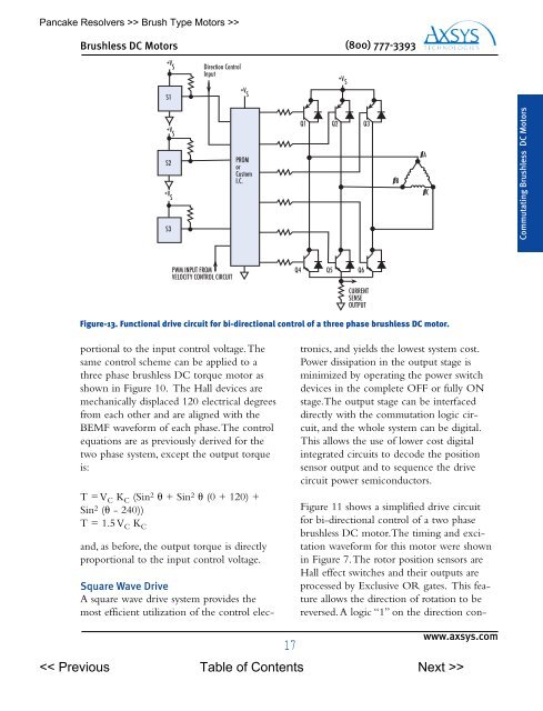
portional to the input control voltage.The<br />
same control scheme can be applied to a<br />
three phase brushless DC torque motor as<br />
shown in Figure 10. The Hall devices are<br />
mechanically displaced 120 electrical degrees<br />
from each other and are aligned with the<br />
BEMF waveform of each phase.The control<br />
equations are as previously derived for the<br />
two phase system, except the output torque<br />
is:<br />
T = VC KC (Sin2 + Sin2 (0 + 120) +<br />
Sin2 ( - 240))<br />
T = 1.5 VC KC and, as before, the output torque is directly<br />
proportional to the input control voltage.<br />
Square Wave Drive<br />
A square wave drive system provides the<br />
most efficient utilization of the control elec-<br />
+V S<br />
PROM<br />
or<br />
Custom<br />
I.C.<br />
(800) 777-3393<br />
tronics, and yields the lowest system cost.<br />
Power dissipation in the output stage is<br />
minimized by operating the power switch<br />
devices in the complete OFF or fully ON<br />
stage.The output stage can be interfaced<br />
directly with the commutation logic circuit,<br />
and the whole system can be digital.<br />
This allows the use of lower cost digital<br />
integrated circuits to decode the position<br />
sensor output and to sequence the drive<br />
circuit power semiconductors.<br />
Figure 11 shows a simplified drive circuit<br />
for bi-directional control of a two phase<br />
brushless DC motor.The timing and excitation<br />
waveform for this motor were shown<br />
in Figure 7.The rotor position sensors are<br />
Hall effect switches and their outputs are<br />
processed by Exclusive OR gates. This feature<br />
allows the direction of rotation to be<br />
reversed. A logic “1” on the direction con-<br />
www.axsys.com<br />
><br />
Q1<br />
+V S<br />
Q2 Q3<br />
Q4 Q5 Q6<br />
CURRENT<br />
SENSE<br />
OUTPUT<br />
Figure-13. Functional drive circuit for bi-directional control of a three phase brushless DC motor.<br />
0B<br />
0A<br />
0C<br />
Commutating Brushless DC Motors