

please click here - General Dynamics Global Imaging Technologies
please click here - General Dynamics Global Imaging Technologies
please click here - General Dynamics Global Imaging Technologies

You also want an ePaper? Increase the reach of your titles
YUMPU automatically turns print PDFs into web optimized ePapers that Google loves.
Pancake Resolvers >> Brush Type Motors >><br />
Brushless DC Motors<br />
position to the required resolution.<br />
4. Commutation logic and switching electronics<br />
to covert rotor position information<br />
to the proper stator phase excitation.<br />
Stator<br />
The stator for a brushless DC motor is a<br />
laminated steel core with coils of magnet<br />
wire embedded and connected in two or<br />
more phases so that by sequentially exciting<br />
these phase winding, a rotating electromagnetic<br />
field can be generated.<br />
Since both iron and copper losses in the<br />
brushless DC motor take place in the stator,<br />
generated heat is easily transferred to the<br />
surroundings. A motor with an inner rotor is<br />
better in this regard due to the larger stator<br />
area in contact with the mounting surfaces.<br />
Rotors<br />
In all continuous rotation brushless DC<br />
motors, the permanent magnetic field is on<br />
the rotor.The winding supplying the rotating<br />
electromagnetic field are in the stator.<br />
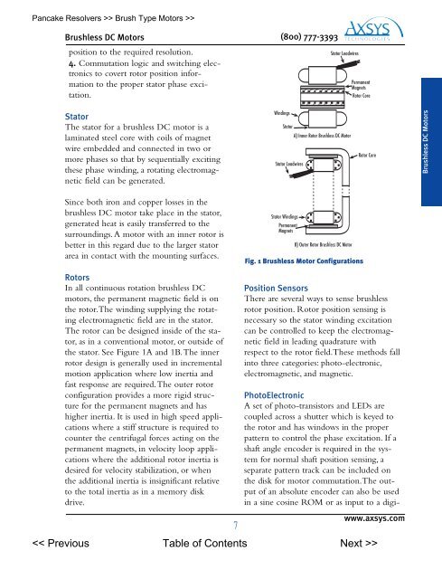
The rotor can be designed inside of the stator,<br />
as in a conventional motor, or outside of<br />
the stator. See Figure 1A and 1B.The inner<br />
rotor design is generally used in incremental<br />
motion application w<strong>here</strong> low inertia and<br />
fast response are required.The outer rotor<br />
configuration provides a more rigid structure<br />
for the permanent magnets and has<br />
higher inertia. It is used in high speed applications<br />
w<strong>here</strong> a stiff structure is required to<br />
counter the centrifugal forces acting on the<br />
permanent magnets, in velocity loop applications<br />
w<strong>here</strong> the additional rotor inertia is<br />
desired for velocity stabilization, or when<br />
the additional inertia is insignificant relative<br />
to the total inertia as in a memory disk<br />
drive.<br />
(800) 777-3393<br />
Stator Leadwires<br />
Permanent<br />
Magnets<br />
Position Sensors<br />
T<strong>here</strong> are several ways to sense brushless<br />
rotor position. Rotor position sensing is<br />
necessary so the stator winding excitation<br />
can be controlled to keep the electromagnetic<br />
field in leading quadrature with<br />
respect to the rotor field.These methods fall<br />
into three categories: photo-electronic,<br />
electromagnetic, and magnetic.<br />
PhotoElectronic<br />
A set of photo-transistors and LEDs are<br />
coupled across a shutter which is keyed to<br />
the rotor and has windows in the proper<br />
pattern to control the phase excitation. If a<br />
shaft angle encoder is required in the system<br />
for normal shaft position sensing, a<br />
separate pattern track can be included on<br />
the disk for motor commutation.The output<br />
of an absolute encoder can also be used<br />
in a sine cosine ROM or as input to a digi-<br />
www.axsys.com<br />
><br />
Windings<br />
Stator<br />
Stator Leadwires<br />
Stator Windings<br />
Permanent<br />
Magnets<br />
A) Inner Rotor Brushless DC Motor<br />
B) Outer Rotor Brushless DC Motor<br />
Rotor Core<br />
Fig. 1 Brushless Motor Configurations<br />
Rotor Core<br />
Brushless DC Motors