VHF Communication Antennas VHF Communication Antennas
VHF Communication Antennas VHF Communication Antennas
VHF Communication Antennas VHF Communication Antennas

You also want an ePaper? Increase the reach of your titles
YUMPU automatically turns print PDFs into web optimized ePapers that Google loves.
Avionics & Accessories<br />
RA Miller (RAMI)<br />
172<br />
<strong>VHF</strong> <strong>VHF</strong> <strong>Communication</strong> <strong>Antennas</strong> <strong>Antennas</strong><br />
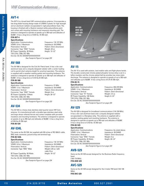
AVT-4<br />
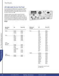
The AVT-4 is a broad-band <strong>VHF</strong> communications antenna. It incorporates a<br />
low drag blade housing design made of LURAN-S plastic for high strength<br />
and an aluminum radiator encapsulated in rigid polyurethane foam. The<br />
housing is finished with a Skydrol resistant white polyurethane paint<br />
and comes with mounting hardware and neoprene mounting pad. The<br />
antenna is designed to operate at speeds up to 350 mph and altitudes of<br />
50,000’. It has a drag force of 0.85 lbs. @ 250 mph.<br />
P/N AVT-4<br />
Specifications<br />
Application: <strong>Communication</strong>s Frequency: 118-137 MHz<br />
VSWR: 3.0 to 1 Maximum Impedance: 50 OHMS<br />
Polarization: Vertical Pattern: Omni-directional<br />
Connector: Type “BNC” Female Weight: 20 oz<br />
RF Power Capability: 30 Watts Height: 13-1/2”<br />
TSO C37d, C38d, DO-160c<br />
Env.Cat. D2-AC SXSXDFSXXXXXXXXXX<br />
See Footprint Figure C on page 223<br />
AV-568<br />
The AV-568 is designed for the Civil Air Patrol band. It has a die-cast<br />
aluminum base and a uniquely designed radiator with a center loading<br />
coil to permit short antenna length for practical operation. The antenna<br />
is supplied with a weather-sealing gasket and mounting hardware. The<br />
antenna is designed to operate at speeds up to 350 mph and altitudes of<br />
50,000’. It has a drag force of 3.43 lbs.@ 250 mph.<br />
P/N AV-568<br />
Specifications<br />
Application: <strong>Communication</strong>s Frequency: 27 MHz<br />
VSWR: 1.5 to 1 Maximum Impedance: 50 OHMS<br />
Polarization: Vertical Pattern: Omni-directional<br />
Connector: Type “BNC” Female Weight: 8 oz<br />
RF Power Capability: 5 Watts Height: 26-1/2”<br />
TSO C37d, C38d, DO-160c<br />
Env.Cat. D2-AC SXSXDFSXXXXXXXXXX<br />
See Footprint Figure A on page 223<br />
AV-534<br />
The AV-534 is a heavy-duty stainless steel quarter-wave <strong>VHF</strong> Com.<br />
antenna. It is manufactured with a durable type stainless steel whip<br />
and large stress-relieved ferrule and comes complete with porcelain<br />
insulators and mounting hardware. The antenna is designed to operate<br />
at speeds of up to 350 mph and altitudes of 50,000’. It has a drag force<br />
of 0.56 lbs.@ 250 mph.<br />
P/N AV-534<br />
AV-534L<br />
The same as the AV-534, but supplied with 96 inches of RG-58A/U cable,<br />
BNC male connector, ground strap and terminal lugs.<br />
P/N AV-534L<br />
Specifications<br />
Application: <strong>Communication</strong>s Frequency: 118-137 MHz<br />
VSWR: 3.0 to 1 Maximum Impedance: 50 OHMS<br />
Polarization: Vertical Pattern: Omni-directional<br />
Connector: Type “BNC” Male Weight: 3.25 oz / with<br />
cable 16 oz<br />
RF Power Capability: 50 Watts Height: 19-1/2”<br />
TSO C37d, C38d, DO-160c<br />
Env.Cat. D2-AC SXSXDFSXXXXXXXXXX<br />
See Footprint Figure K on page 224<br />
AV-15<br />
AV-529<br />
AVB-529<br />
AVC-529<br />
AV-568<br />
The AV-15 is used with aviation, land mobile radio and flight phone bands.<br />
The durably constructed chrome-plated phosphor bronze whip is set in a<br />
teflon insulator and the chrome-plated ball tip provides low noise static<br />
discharge. The antenna is designed to operate at speeds of up to 350 mph<br />
and altitudes up to 50,000’. It has a drag force of 0.75 @ 250 mph.<br />
P/N AV-15<br />
Specifications<br />
Application: <strong>Communication</strong>s Frequency: 450-470 MHz<br />
VSWR: 1.5 to 1 Maximum Impedance: 50 OHMS<br />
Polarization: Vertical Pattern: Omni-directional<br />
Connector: Type “N” Female Weight: 2.5 oz<br />
RF Power Capability: 100 Watts Height: 6-1/4”<br />
TSO C37d, C38d, DO-160c<br />
Env.Cat. D2-AC SXSXDFSXXXXXXXXXX<br />
See Footprint Figure K on page 224<br />
AV-529<br />
The AV-529 is designed for broadband communications (118-136 MHz).<br />
It has a die-cast aluminum base and a uniquely designed radiator<br />
encapsulated in a fiberglass whip. The antenna is supplied with a<br />
weather-sealing gasket and mounting hardware. The antenna is<br />
designed to operate at speeds up to 350 mph and altitudes of 50,000’.<br />
It has a drag force of 3.43 lbs. @ 250 mph.<br />
P/N AV-529<br />
Specifications<br />
Application: <strong>Communication</strong>s Frequency: As noted above.<br />
VSWR: 1.8 to 1 Maximum Impedance: 50 OHMS<br />
Polarization: Vertical Pattern: Omni-directional<br />
Connector: Type “BNC” Female Weight: 8 oz<br />
RF Power Capability: 25 Watts Height: 20-1/4”<br />
TSO C37d, C38d, DO-160c<br />
Env.Cat. D2-AC SXSXDFSXXXXXXXXXX<br />
See Footprint Figure A on page 223<br />
AVB-529<br />
AV-15<br />
AV-534<br />
Same as the AV-529 except designed for the Business Radio frequency<br />
band<br />
(148-174 MHz).<br />
P/N AVB-529<br />
AVC-529<br />
Same as the AV-529 except designed for the 2 meter FM band (143-149<br />
MHz).<br />
P/N AVC-529<br />
2 1 4 . 3 2 0 . 9 7 7 0 D a l l a s Av i o n i c s 8 0 0 . 5 2 7 . 2 5 8 1<br />
AVT-4
Navigation Navigation <strong>Antennas</strong> <strong>Antennas</strong><br />
AV-64 Marker Beacon Antenna<br />
The AV-64 is a boat type marker beacon antenna designed for very low<br />
drag. It is constructed of an acrylonitrile-styrene-acrylic (ASA) shell with<br />
the internal parts encapsulated in rigid urethane foam for mechanical<br />
and electrical stability. The white color allows maximum performance<br />
without losses due to color pigments or unseen dirt. Supplied with<br />
cellular neoprene mounting pad and hardware. The antenna is designed<br />
to operate at speeds up to 350 mph and altituded up to 50,000’. It has a<br />
drag force of 0.22 lbs. at 250 mph. This antenna is a direct replacement<br />
for Comant’s model CI-102.<br />
P/N AV-64<br />
Specifications<br />
Electrical<br />
Frequency 75 MHz<br />
VSWR 1.4 to 1.0 maximum<br />
Impedance 50 OHMS<br />
Weight 0.5 lbs.<br />
Height 2.2”<br />
Connector BNC (female)<br />
RF Power Capability Receive only<br />
Environmental Category [D2]XACA[SXX]<br />
XSXDFSXXXXX[XXX]X[XXXX]XXX<br />
2 1 4 . 3 2 0 . 9 7 7 0 D a l l a s Av i o n i c s 8 0 0 . 5 2 7 . 2 5 8 1<br />
Avionics & Accessories<br />
RA Miller (RAMI)<br />
173
Avionics & Accessories<br />
RA Miller (RAMI)<br />
174<br />
Navigation Navigation <strong>Antennas</strong><br />
<strong>Antennas</strong><br />
AV-12<br />
The AV-12 is a VOR receive only antenna which uses a highly efficient<br />
technique of molding the elements directly into a high-impact thermosetting<br />
bakelite center insulator. The stainless steel elements are ground<br />
to close tolerances to provide a low profile. The antenna is designed to<br />
operate at speeds of up to 350 mph and altitudes up to 50,000’. It has a<br />
drag force of 0.92 lbs.@ 250 mph.<br />
P/N AV-12<br />
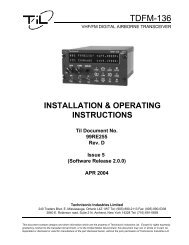
AV-569<br />
The AV-569 is a Boat Type Marker Beacon antenna designed for very low<br />
drag. It is constructed of an acrylonitrile-styrene-acrylic (ASA) shell with<br />
the internal parts encapsulated in rigid urethane foam for mechanical<br />
and electrical stability. The white color allows maximum performance<br />
without losses due to color pigments or unseen dirt. Supplied with<br />
cellular neoprene mounting pad and hardware. The antenna is designed<br />
to operate at speeds of up to 350 mph and altitudes up to 50,000’. It has<br />
a drag force of 0.20 lbs.@ 250 mph.<br />
P/N AV-569<br />
Specifications<br />
Application: Marker beacon Frequency: 75 MHz<br />
VSWR: 1.6:1 maximum Impedance: 50 OHMS<br />
Connector: BNC (female) Weight: 6.25 oz.<br />
RF Power Capability: Receive only Height: 2-1/2”<br />
TSO C35d, DO-160c<br />
Env.Cat. D2-AC SXSXDFSXXXXXXXXXX<br />
See Footprint Figure E on page 223<br />
AV-545<br />
The AV-545 is an ADF Sense antenna supplied with “Government<br />
Approved” self-gripping jaws and a stainless steel small diameter low<br />
drag tension device for reliable installation. The unit is also supplied<br />
with 23' of type 6370-2 copperweld polycovered antenna wire for<br />
minimum stretching, mounting bracket and hardware, rubber pad<br />
and ASA insulator with feed-thru. The antenna is designed to operate<br />
at speeds of up to 350 mph and altitudes up to 50,000’. It has a drag<br />
force of 0.75 lbs.@ 250 mph.<br />
P/N AV-545<br />
AV-545 Specifications<br />
Application: ADF Sense Frequency: 190-1750 KHz<br />
Impedance: 50 OHMS Weight: 13 oz.<br />
Connector: BNC (female) Length: 24’ maximum<br />
(field cuttable)<br />
RF Power Capability: Receive only<br />
TSO C41d, DO-160c<br />
Env.Cat. D2-ACXXXSXDFSXXXXXXXXXX<br />
See Footprint Figure J on page 224<br />
AV-12L<br />
Same as the AV-12 except a 25' cable with integral balun is<br />
also supplied.<br />
P/N AV-12L<br />
Specifications<br />
Application: VOR Frequency: 108-118 MHz<br />
VSWR: 2.2:1 maximum Impedance: 50 OHMS<br />
Connector: BNC (male) Weight: 5.5 oz. /<br />
with cable 14 oz.<br />
RF Power Capability: Receive only Width across tips: 23-1/2”<br />
TSO C40c, DO-160c<br />
Env.Cat. D2-AC SXSXDFSXXXXXXXXXX<br />
See Footprint Figure I on page 224<br />
AV-532<br />
The AV-532 is a VOR receive only antenna which consists of taper<br />
ground high-strength 17-7PH stainless steel elements to reliably<br />
withstand vibration and wind loads. The insulators are weather-sealed<br />
compression-molded bakelite with the mounting holes provided. The unit<br />
may be mounted with the V pointed either forward or aft. The antenna<br />
is designed to operate at speeds of up to 350 mph and altitudes up to<br />
50,000’. It has a drag force of 3.42 lbs.@ 250 mph.<br />
P/N AV-532<br />
AV-532L<br />
The same as the AV-532 except a 30' cable with integral balun is<br />
also supplied.<br />
P/N AV-532L<br />
Specifications<br />
Application: VOR Frequency: 108-118 MHz<br />
VSWR: 2.0:1 maximum Impedance: 50 OHMS<br />
Connector: BNC (male) Weight: 11 oz./w/cable 14 oz.<br />
RF Power Capability: Receive only Width across tips: 23-1/2”<br />
TSO C40c, DO-160c<br />
Env.Cat. D2-AC SXSXDFSXXXXXXXXXX<br />
See Footprint Figure I on page 224<br />
AV-533<br />
AV-569<br />
AV-533<br />
AV-532<br />
AV-12<br />
The AV-533 is a sled type marker beacon antenna constructed of a high<br />
strength 17-7PH stainless steel element, feed system, and low absorption,<br />
high strength phenolic standoff insulator. Stainless steel mounting<br />
hardware is also included. The antenna is designed to operate at speeds<br />
of up to 350 mph and altitudes up to 50,000’. It has a drag force of<br />
1.02 lbs.@ 250 mph.<br />
P/N AV-533<br />
Specifications<br />
Application: Marker beacon Frequency: 75 MHz<br />
VSWR: 1.1:1 maximum Impedance: 50 OHMS<br />
Connector: Split end lugs Weight: 7.25 oz.<br />
RF Power Capability: Receive only<br />
Height: 2-1/2”<br />
Length: 29”<br />
TSO C35d, DO-160c<br />
Env.Cat. D2-ACXXXSXDFSXXXXXXXXXX<br />
See Footprint Figure H on page 224<br />
2 1 4 . 3 2 0 . 9 7 7 0 D a l l a s Av i o n i c s 8 0 0 . 5 2 7 . 2 5 8 1<br />
AV-545
Navigation Navigation <strong>Antennas</strong><br />
<strong>Antennas</strong><br />
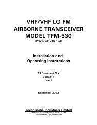
AV-741<br />
The AV-741 is designed for use with DME/Transponder sets. It is<br />
constructed from an aluminum casting which is capable of withstanding<br />
particle erosion to speeds of up to Mach 2. The antenna is produced<br />
to Military Specifications Mil-A-25708 & Mil-A-25708/1 and is qualified<br />
environmentally to Mil-Std-810. It has an operational temperature range<br />
of -55°C to 250°C (-67° to 482°F), can withstand a static load of 15psi<br />
perpendicular to the blade, and is operational to altitudes of 100,000’. The<br />
exterior is finished with a white polyurethane coating which is Skydrol<br />
resistant. The antenna is designed to operate at speeds of up to 350 mph<br />
and altitudes up to 50,000’. It has a drag force of 0.35 lbs.@ 250 mph.<br />
P/N AV-741<br />
Specifications<br />
Application: Transponder/DME Frequency: 980-1220 MHz<br />
VSWR: 1.4:1 maximum Impedance: 50 OHMS<br />
Polarization: Vertical Pattern: Omnidirectional<br />
Connector: HN (female) Weight: .5 lbs.<br />
RF Power Capability: 4 kW peak, Height: 3.3”<br />
0.1 kW continuous<br />
See Footprint Figure F on page 223<br />
AVR-546<br />
The AVR-546 is a transponder antenna durably constructed with a<br />
chrome-plated phosphor bronze radiator set in a teflon insulator. Rigid<br />
specifications assure reliable performance in all kinds of weather. The<br />
antenna is designed to operate at speeds of up to 350 mph and altitudes<br />
up to 50,000’. It has a drag force of 0.41 lbs.@ 250 mph.<br />
P/N AV-546<br />
Specifications<br />
Application: Transponder Frequency: 1030-1090 MHz<br />
VSWR: 1.3:1 maximum Impedance: 50 OHMS<br />
Polarization: Vertical Pattern: Omnidirectional<br />
Connector: C (female) Weight: 2 oz.<br />
RF Power Capability: 250 Watts Pulse Height: 3”<br />
TSO C74c, DO-160c<br />
Env.Cat. D2-AC SXSXDFSXXXXXXXXXX<br />
See Footprint K on page 224<br />
AV-22<br />
AVR-546<br />
AV-9<br />
The AV-9 is a broadband DME (“L” Band) antenna durably constructed<br />
around a Type “N” low-loss connector. The large diameter radiator of<br />
polished chrome-plated aluminum gives the broad coverage required<br />
with this type of antenna. The antenna is designed to operate at speeds<br />
of up to 350 mph and altitudes up to 50,000’. It has a drag force of<br />
0.85 lbs.@ 250 mph.<br />
P/N AV-9<br />
Specifications<br />
Application: DME Frequency: 980-1220 MHz<br />
VSWR: 1.75:1 maximum Impedance: 50 OHMS<br />
Polarization: Vertical Pattern: Omnidirectional<br />
Connector: N (female) Weight: 3 oz.<br />
RF Power Capability: 250 Watt pulse Height: 2-1/2”<br />
TSO C66c, DO-160c<br />
Env.Cat. D2-AC SXSXDFSXXXXXXXXXX<br />
See Footprint Figure K on page 224<br />
AV-22<br />
The AV-22 is a transponder antenna which utilizes a “BNC” connector<br />
that allows for a smaller mounting hole. The antenna is designed to<br />
operate at speeds of up to 350 mph and altitudes up to 50,000’. It has<br />
a drag force of 0.41 lbs.@ 250 mph.<br />
P/N AV-22<br />
Specifications<br />
Application: Transponder Frequency: 1030-1090 MHz<br />
VSWR: 1.3:1 maximum Impedance: 50 OHMS<br />
Polarization: Vertical Pattern: Omnidirectional<br />
Connector: BNC (female) Weight: 1 oz<br />
RF Power Capability: 250 Watts Pulse Height: 3”<br />
TSO C74c, DO-160c<br />
Env.Cat. D2-AC SXSXDFSXXXXXXXXXX<br />
See Footprint Figure K on page 224<br />
AV-741<br />
2 1 4 . 3 2 0 . 9 7 7 0 D a l l a s Av i o n i c s 8 0 0 . 5 2 7 . 2 5 8 1<br />
AV-9<br />
Avionics & Accessories<br />
RA Miller (RAMI)<br />
175
Avionics & Accessories<br />
RA Miller (RAMI)<br />
DME DME Antenna Antenna<br />
AV-74 DME/Transponder Antenna<br />
The AV-74 is a broadband blade style antenna for transponder or DME<br />
application. It’s housing is constructed of an acrylonitrile-styrene-acrylic<br />
(ASA) shell. The white color allows maximum performance without losses<br />
due to color pigments or unseen dirt. Supplied with cellular neoprene<br />
mounting pad and hardware. The antenna is designed to operate at<br />
speeds up to 350 mph and altitudes up to 50,000’. It has a drag force of<br />
0.09 lbs. at 250 mph. This antenna is a direct replacement for Comant’s<br />
model CI-105.<br />
P/N AV-74<br />
Specifications<br />
Electrical<br />
Frequency 960 to 1220 MHz<br />
VSWR 1.5 to 1.0 maximum<br />
Impedance 50 OHMS<br />
Weight 0.2 lbs.<br />
Height 3.4”<br />
Connector BNC (female)<br />
RF Power Capability 2.5 kW peak<br />
Environmental Category [D2]XACA[SXX]<br />
XSXDFSXXXXX[XXX]X[XXXX]XXX<br />
176 2 1 4 . 3 2 0 . 9 7 7 0 D a l l a s Av i o n i c s 8 0 0 . 5 2 7 . 2 5 8 1
Antenna Antenna Couplers<br />
Couplers<br />
AV-547<br />
The AV-547 coupler feeds two navigation receivers from one antenna.<br />
The matching circuitry is enclosed in a durable, light weight aluminum<br />
housing for superior mechanical and environmental stability. The coupler<br />
operates at altitudes of up to 50,000’.<br />
P/N AV-547<br />
Specifications<br />
Application: Nav. Frequency: 108-118 MHz<br />
VSWR: 1.4:1 maximum Impedance: 50 OHMS<br />
Insertion loss: 3 dB Avg/5 dB maximum Isolation: 30 dB minimum<br />
Connector: Type “BNC” Females Weight: 3.5 oz.<br />
RF Power Capability: Receive only Dimensions: 2”x 1-3/4”<br />
x 1-1/8”<br />
TSO C36e, C40c, DO-160c<br />
Env.Cat. D2-BC SXXXXFXXXXXXXXXXX<br />
See Footprint Figure D on page 223<br />
AV-571<br />
AV-547<br />
The AV-571 coupler splits the signal from a VOR-Type antenna to feed<br />
two NAV and one Glideslope receivers. The coupler’s construction is<br />
similar to the AV-547 and AV-570 couplers and operates to the same<br />
altitude as both.<br />
P/N AV-571<br />
Specifications<br />
Application: Nav & Glideslope Frequency: 108-118<br />
& 329-333 MHz<br />
Filtering: 30dB min/40dB avg. Impedance: 50 OHMS<br />
Insertion loss: 3.75 dB Max. Isolation: 22 dB Min./<br />
35 dB Avg.<br />
Connector: (4) BNC (female) Weight: 3.5 oz.<br />
RF Power Capability: Receive only Dimensions: 2”x 1-3/4”<br />
x 1-1/8”<br />
TSO C34e, C36e, C40c, DO-160c<br />
Env.Cat. D2-BC SXXXXFXXXXXXXXXXX<br />
See Footprint Figure D on page 223<br />
AV-570 AV-571<br />
AV-570<br />
The AV-570 coupler splits the signal from a VOR-Type NAV antenna to<br />
feed NAV and Glideslope receivers. The coupler’s construction is similar<br />
to the AV-547 coupler and operates at altitudes up to 50,000’.<br />
P/N AV-570<br />
Specifications<br />
Application: Nav & Glideslope Frequency: 108-118<br />
& 329-333 MHz<br />
Filtering: 30dB min/ 40dB avg. Impedance: 50 OHMS<br />
Insertion loss: 1 dB Max. Isolation: 38 dB Min.<br />
Connector: (3) BNC (female) Weight: 3.5 oz.<br />
RF Power Capability: Receive only Dimensions: 2”x 1-3/4”<br />
x 1-1/8”<br />
TSO C34e, C36e, C40c, DO-160c<br />
Env.Cat. D2-BC SXXXXFXXXXXXXXXXX<br />
See Footprint Figure D on page 223<br />
2 1 4 . 3 2 0 . 9 7 7 0 D a l l a s Av i o n i c s 8 0 0 . 5 2 7 . 2 5 8 1<br />
Avionics & Accessories<br />
RA Miller (RAMI)<br />
177
Avionics & Accessories<br />
RA Miller (RAMI)<br />
178<br />
Ground/Air Ground/Air <strong>Communication</strong>s<br />
AV-1<br />
The AV-1 is a base station antenna for communications with ground<br />
vehicles or aircraft. It has heavy-duty construction with 3/8” diameter<br />
aluminum radials, a 1” diameter aluminum tube radiator, and is iriditetreated<br />
for durability. It mounts easily to a 1” diameter pipe or a 1-1/4”<br />
O.D. tube with locking set screws. A built-in gap-type lightning arrestor<br />
is an important design feature. The antenna requires no additional tuning<br />
and is designed to withstand wind speeds of up to 100 mph.<br />
P/N AV-1<br />
Specifications<br />
Application: <strong>VHF</strong> communications Frequency: 118-137 MHz<br />
VSWR: 2.0:1 maximum Impedance: 50 OHMS<br />
Polarization: Vertical Pattern: Omnidirectional<br />
Connector: Accepts PL-259 Weight: 2.75 lbs.<br />
RF Power Capability: 1000 Watts Height: 34”<br />
AV-5<br />
The AV-5 is an economical Ground Plane base station antenna. It is<br />
ideally suited for use with Unicom transceivers and is field tunable for<br />
the frequency band desired. The radial arm angle is designed to give<br />
optimum VSWR at the tuned frequency. Durably constructed of high<br />
quality materials for a long operational life, the antenna is designed<br />
to withstand wind speeds of up to 100 mph. Field tunable for<br />
frequency desired.<br />
P/N AV-5<br />
Specifications<br />
Application: <strong>Communication</strong>s Frequency: 118-137 MHz<br />
VSWR: 1.5:1 maximum Impedance: 50 OHMS<br />
Polarization: Vertical Pattern: Omnidirectional<br />
Connector: Accepts PL-259 Weight: 1.0 lbs.<br />
RF Power Capability: 100 Watts Height: 34”<br />
AV-6<br />
AV-5<br />
AV-1<br />
The AV-6 is a Cable Assembly consisting of 50 foot of RG-58/U low<br />
loss transmission line, a PL-259 connector at one end and a BNC male<br />
connector at the other. The cable assembly is commonly used with the<br />
AV-1 and AV-5 Ground Based <strong>Antennas</strong>.<br />
P/N AV-6<br />
AV-2<br />
The AV-2 is a high performance vehicular antenna for use on all<br />
surface vehicles where communication on the aircraft <strong>VHF</strong> frequency<br />
band is required. Heavy duty constructed with a tapered 17-7PH<br />
stainless steel whip and spring mount. All exposed fittings are<br />
chrome-plated brass or stainless steel. The antenna is supplied<br />
with 12 feet of cable with connectors. Mounting is easily achieved on<br />
rooftop, cowl, fender or other suitable location. DC grounded for low<br />
noise pick-up. The unit is also field tunable to the 25-50 MHz and<br />
130-174 MHz ranges.<br />
P/N AV-2<br />
Specifications<br />
Application: <strong>Communication</strong>s Frequency: 118-137 MHz<br />
VSWR: 1.5:1 maximum Impedance: 50 OHMS<br />
Polarization: Vertical Pattern: Omnidirectional<br />
Connector: PL-259 Weight: 2.50 lbs.<br />
RF Power Capability: 100 Watts Height: 55” maximum<br />
(field cuttable)<br />
See Footprint Figure K on page 224<br />
AV-3<br />
The AV-3 is a low profile snap-in mounting quarter-wave antenna for use<br />
on surface vehicles. It has a solderless cable connection at the antenna<br />
and is supplied with 12 feet of cable and PL-259 connector. The antenna<br />
is field tunable by simply cutting the whip to the required length.<br />
P/N AV-3<br />
Specifications<br />
Application: <strong>Communication</strong>s Frequency: 108-512 MHz<br />
VSWR: 1.5:1 maximum Impedance: 50 OHMS<br />
Polarization: Vertical Pattern: Omnidirectional<br />
Connector: PL-259 Weight: 7 oz.<br />
RF Power Capability: 100 Watts Height: 27-1/2”<br />
See Footprint Figure K on page 224<br />
2 1 4 . 3 2 0 . 9 7 7 0 D a l l a s Av i o n i c s 8 0 0 . 5 2 7 . 2 5 8 1<br />
AV-2<br />
AV-3
Military/Commercial <strong>Communication</strong>s<br />
AT-256A/ARC<br />
The AT-256A/ARC is used for airborne communications on various<br />
fixed-wing aircraft and helicopters. The antenna is manufactured to<br />
Military Specifications MIL-A-5815 & MIL-A-5815/1. It is designed to<br />
operate at the extreme temperature range of -54°C to 125°C (-65° to<br />
257°F) with intermittent operation at 150°C (302°F) and can withstand<br />
a static load of 55 MPA (8psi) perpendicular to the blade, with an<br />
ultimate of 83 MPA (12psi). The antenna is protected by an anodic<br />
coating to prevent corrosion. The antenna’s sealability is tested to<br />
21,340m (70,000') altitude.<br />
P/N AT-256A/ARC<br />
Specifications<br />
Application Airborne communications<br />
Frequency 225 to 400 MHz<br />
Impedance 50 OHMS (nominal)<br />
VSWR 2.0:1 maximum<br />
Polarization Vertical<br />
Pattern Omnidirectional<br />
Connector N (female)<br />
Weight 0.91 Kg (2 lbs.) maximum<br />
Height 9.140” maximum<br />
RF Power Capability 50 Watts average<br />
Gain (Ref to a 1/4 wave Monopole) -1 dB > 225-400 MHz<br />
See Footprint Figure L on page 225<br />
UH-408<br />
The UH-408 is used for airborne communications on various fixed-wing<br />
aircraft and helicopters. The antenna is qualified to Military Specification<br />
MIL-E-5272 and MIL-E-5400. The antenna is designed to operate at<br />
the extreme temperature range of -54°C to 93°C (-65° to 200°F) and at<br />
altitudes of up to 18,293m (60,000'). It is protected by an anodic coating<br />
to prevent corrosion.<br />
P/N UH-408<br />
Specifications<br />
Application Airborne communications<br />
Frequency 225 to 425 MHz<br />
Impedance 50 OHMS (nominal)<br />
VSWR 2.0:1 maximum<br />
Polarization Vertical<br />
Pattern Omnidirectional<br />
Connector N (female)<br />
Weight 0.91 Kg (2 lbs.) maximum<br />
Height 7 11/16”<br />
RF Power Capability 50 Watts average<br />
Gain (Ref to a 1/4 wave Monopole) -1 dB > 225-425 MHz<br />
See Footprint Figure N on page 225<br />
AS-3808/ARC<br />
The AS-3808/ARC is designed for High Power airborne UHF<br />
communications. The antenna is manufactured to Electrospace<br />
Systems Specification EM-A0051 which specifies environmental tests<br />
per MIL-STD-810, an operating altitude of 21,340m (70,000'). It is<br />
painted with a Skydrol resistant urethane coating per MIL-C-83286,<br />
Color White No. 17925. The antenna is a one-piece blade to replace<br />
the AT-1076/ARC antenna.<br />
P/N AS-3808/ARC<br />
Specifications<br />
Application Airborne communications<br />
Frequency 225 to 400 MHz<br />
Impedance 50 OHMS (nominal)<br />
VSWR 2.0:1 maximum<br />
Polarization Vertical<br />
Pattern Omnidirectional<br />
Connector HN (female)<br />
Weight 0.45 Kg (1.0 lbs.)<br />
Height 8.245”<br />
RF Power Capability 1500 Watts continuous<br />
Gain (Ref to a 1/4 wave Monopole) +3 to -1 dBi<br />
See Footprint Figure M on page 225<br />
See product images on next page.<br />
2 1 4 . 3 2 0 . 9 7 7 0 D a l l a s Av i o n i c s 8 0 0 . 5 2 7 . 2 5 8 1<br />
Avionics & Accessories<br />
RA Miller (RAMI)<br />
179
Avionics & Accessories<br />
RA Miller (RAMI)<br />
180<br />
UHF/<strong>VHF</strong> UHF/<strong>VHF</strong> <strong>Communication</strong>s<br />
AT-1108/ARC<br />
AT-256/ARC<br />
AT-1108/ARC<br />
The AT-1108/ARC is a combined <strong>VHF</strong>/UHF airborne communications<br />
antenna designed for usage with both fixed-wing and rotary-wing<br />
aircraft. The antenna housing is fiberglass epoxy designed to withstand<br />
the exposure to sand and dust particles of desert areas and is foam filled<br />
to reduce the effect of extreme temperature changes, extreme humidity<br />
and excessive shock and vibration. The antenna is produced to Military<br />
Specification Mil-A-55680 and has continuous operation at altitudes up to<br />
15,244m (50,000') and temperatures of -54°C to 55°C (-48° to 131°F). It can<br />
withstand the impact shock of 30g and the steady-state acceleration of<br />
6g. The isolation between bands is ≥ 40 dB. A conductive gasket for<br />
positive grounding and sealing is included. The antenna is coated with<br />
a Skydrol resistant lusterless black epoxy paint.<br />
P/N AT-1108/ARC<br />
Specifications<br />
Application Airborne communications<br />
Frequency 116-152 & 225-400 MHz<br />
Impedance 50 OHMS (nominal)<br />
VSWR 3:1 maximum<br />
Polarization Vertical<br />
Pattern Omnidirectional<br />
Connector BNC (<strong>VHF</strong>) & TNC (UHF)<br />
(female)<br />
Weight 1.6 Kg (3.5 lbs.) maximum<br />
Height 14.437”<br />
RF Power Capacity 50 Watts average<br />
Gain (Ref to a 1/4 wave Dipole) -6dB Min. all freq.’s<br />
See Footprint Figure Q on page 225<br />
AS-3808/ARC<br />
AT-1108-1<br />
AT-1108-1<br />
UH-408<br />
The AT-1108-1 is a combined <strong>VHF</strong>/UHF airborne communications<br />
antenna offering less drag than the AT-1108/ARC. It has a narrower<br />
leading edge and body. The outside surfaces are abrasive resistant<br />
fiberglass epoxy and the inside is filled with foam to reduce the effect<br />
of extreme temperature changes, extreme humidity and excessive<br />
shock and vibration. The antenna is manufactured to meet the electrical<br />
requirements of Mil-E-5400 and the environmental requirements of<br />
MIL-STD-810. Drag force on the antenna at Sea Level and at zero<br />
(0) angle of attack is 2.2 Kg (1.0 lbs.) at 4330 km/hr (250mph) and<br />
5.5 Kg (2.5 lbs.) at 6928 km/hr (400mph). The isolation between bands<br />
is ≥ 40 dB. A conductive gasket for positive grounding and sealing is<br />
included. It is coated with a Skydrol resistant black epoxy paint.<br />
P/N AT-1108-1<br />
Specifications<br />
Application Airborne communications<br />
Frequency 116-152 & 225-400 MHz<br />
Impedance 50 OHMS (nominal)<br />
VSWR 3:1 maximum<br />
Polarization Vertical<br />
Pattern Omnidirectional<br />
Connector BNC (<strong>VHF</strong>) & TNC (UHF)<br />
(female)<br />
Weight 1.6 Kg (3.5 lbs.) maximum<br />
Height 14.4”<br />
RF Power Capacity 50 Watts average<br />
Gain (Ref to a 1/4 wave Dipole) -6dB Min. all freq.’s<br />
See Footprint Figure R on page 225<br />
2 1 4 . 3 2 0 . 9 7 7 0 D a l l a s Av i o n i c s 8 0 0 . 5 2 7 . 2 5 8 1
Military/Commercial <strong>Communication</strong>s<br />
37P-4<br />
The 37P-4 is designed for use with Glide Slope receivers for reliable<br />
performance. The antenna is lightweight and is suitable for mounting<br />
either in a radome or externally on the aircraft. The antenna is provided<br />
with an adapter plate with an 11” radius for mounting on rounded<br />
fuselages. The 37P-4 has an “N” type female connector and is finished<br />
with a chemical film coating per Military Specification MIL-C-5541,<br />
Class 1A for maximum corrosion protection in a salt-laden atmosphere.<br />
P/N 37P-4<br />
Specifications<br />
See Footprint Figure T on page 225<br />
Application Glide slope<br />
Frequency 329-336 MHz<br />
Impedance 52 OHMS/unbalanced line<br />
VSWR 2.0:1 maximum<br />
Polarization Horizontal<br />
Pattern Forward directional<br />
Connector N (female)<br />
Weight 0.7 lbs.<br />
Height 6”<br />
RF Power Capability Receive only<br />
AT-640A/ARN<br />
The AT-640A/ARN is a receive-only <strong>VHF</strong> Marker Beacon antenna used<br />
on both fixed-wing and rotary-wing aircraft. The antenna will meet the<br />
requirements of Military Specification MIL-A-5999 for electrical and<br />
environmental performance. It is finished with a white Skydrol resistance<br />
polyurethane paint in accordance with MIL-C-81773. The antenna has an<br />
operating temperature -40°C to 60°C (-40° to 140°F). Precipitation static<br />
is minimized through the use of a foam-filled fiberglass construction.<br />
The foam also reduces the effects of vibration, shock and temperature<br />
extremes.<br />
P/N AT-640A/ARN<br />
Specifications<br />
See Footprint Figure S on page 225<br />
Application Marker beacon<br />
Frequency 75 MHz<br />
Impedance 50 OHMS (nominal)<br />
VSWR 2.5:1 maximum<br />
Polarization Parallel fore & aft of aircraft<br />
Pattern Lobally downward<br />
Connector C (female)<br />
Weight 0.45 kg. (1.0 lbs.) maximum<br />
Height 2.5” maximum<br />
RF Power Capability Receive only<br />
2 1 4 . 3 2 0 . 9 7 7 0 D a l l a s Av i o n i c s 8 0 0 . 5 2 7 . 2 5 8 1<br />
Avionics & Accessories<br />
RA Miller (RAMI)<br />
181
Avionics & Accessories<br />
RA Miller (RAMI)<br />
182<br />
Navigation/Transponder/DML<br />
AT-740/A<br />
The AT-740/A is used for airborne radar interrogation on various<br />
fixed-wing aircraft. Manufactured to Military Specifications MIL-A-25707<br />
and MIL-A-25707/1, it is designed to operate at the extreme temperature<br />
range of -55°C to 205°C (-67° to 401°F). The antenna is a flush-mounted,<br />
cavity-back slot antenna constructed of aluminum with a fiberglass<br />
radome. It has a type BNC sampling probe and is protected by an<br />
anodic coating to prevent corrosion.<br />
P/N AT-740/A<br />
Specifications<br />
Application DME, Tacan, Beacon<br />
Frequency 960-1220 MHz<br />
Impedance 50 OHMS (nominal)<br />
VSWR (antenna) 1.8:1 maximum<br />
VSWR (sample probe) 1.5:1 maximum<br />
Polarization Vertical<br />
Pattern Omnidirectional<br />
Connector HN (antenna) & BNC<br />
(female probe)<br />
Weight 0.45 Kg (1.0 lbs.) maximum<br />
Dimensions Flush mount, 8”<br />
Dia. x 1.5” thick<br />
RF Power Capability 4 kW peak, 100 Watts average<br />
Gain (Ref 1/4 wave monopole) -0.5 dB > 960-1220 MHz<br />
Probe Attenuation 17.5 dB ≥ 1.5 dB > Freq. Rng.<br />
AT-740/A<br />
See Footprint Figure V on page 226<br />
AT-884<br />
AT-741B/B<br />
AT-741B/B<br />
The AT-741B/B is designed for use with DME, Tacan and Beacon sets.<br />
The antenna is manufactured to Military Specifications MIL-A-25708 and<br />
MIL-A-25708/1 and qualified environmentally to MIL-STD-810. It operates<br />
within a temperature range of -55°C to 250°C (-67° to 482°F) and can<br />
withstand a static load of 15 psi perpendicular to the blade. The antenna<br />
is operational to altitudes of 100,000' and is finished with a Skydrol<br />
resistant lusterless black polyurethane coating.<br />
P/N AT-741B/B<br />
Specifications<br />
Application DME, Tacan, Beacon<br />
Frequency 960-1220 MHz<br />
Impedance 50 OHMS (nominal)<br />
VSWR 1.4:1 maximum<br />
Polarization Vertical<br />
Pattern Omnidirectional<br />
Connector HN (antenna)<br />
& BNC (female probe)<br />
Weight 0.5 lbs.<br />
Height 3.3”<br />
RF Power Capability 4 kW peak, 0.1 kW continuous<br />
AT-884<br />
See Footprint Figure W on page 226<br />
The AT-884 is designed to receive vertically polarized signals at<br />
1010-1110 MHz and radiate vertically polarized signals at 1090-1110 MHz.<br />
The transponder antenna is constructed to provide functional operation<br />
during all normal maneuvers of the aircraft at all azimuthal headings in<br />
respect to any radial to the interrogating radar location. Manufactured<br />
to Military Specifications MIL-T-55046 & MIL-E-5400, the antenna has<br />
an operating temperature range of -55°C to 55°C (-65° to 130°F) and an<br />
operating altitude of up to 9,146m (30,000'). The outside surfaces are<br />
protected with a chemical resistant urethane coating.<br />
P/N AT-884<br />
Specifications<br />
Application DME, Tacan, Beacon<br />
Frequency 1010-1110 MHz<br />
Impedance 50 OHMS (nominal)<br />
VSWR 1.4:1 maximum<br />
Polarization Vertical<br />
Pattern Omnidirectional<br />
Connector C (female)<br />
Weight 0.75 lbs.<br />
Height 2.426”<br />
RF Power Capability 4 kW peak, 0.1 kW continuous<br />
See Footprint Figure X on page 226<br />
2 1 4 . 3 2 0 . 9 7 7 0 D a l l a s Av i o n i c s 8 0 0 . 5 2 7 . 2 5 8 1
Antenna Antenna Cross Cross Reference Reference Guide<br />
Guide<br />
R.A. Miller Industries Inc.<br />
General Aviation Antenna Cross Reference Guide<br />
Other<br />
MFG's<br />
Decibel<br />
Products<br />
Dayton<br />
Granger<br />
Dorne &<br />
Margolin<br />
Comant<br />
Model<br />
Foot -<br />
Print<br />
Figure<br />
Antenna<br />
Description/Application<br />
RAMI<br />
Model<br />
AV-1 Broad Band Ground Plane Base Station, 118-136 MHz -<br />
K<br />
Ground Vehicle, 118-136 Mhz (Field tuned)<br />
AV-2<br />
K<br />
High Performance Ground Vehicle, 108-512 Mhz<br />
AV-3<br />
AD-11<br />
CI-119<br />
C<br />
Broad Band Blade, 118-136 Mhz<br />
AVT-4<br />
-<br />
Ground Plane Base Station, 118-136 Mhz (Field Tuned)<br />
AV-5<br />
-<br />
Cable Kit for AV-1 and AV-5 Unicom radios, 50 foot<br />
AV-6<br />
K<br />
DME, 980-1220 Mhz<br />
AV-9<br />
CI-109<br />
CI-121<br />
CI-158C<br />
B<br />
<strong>VHF</strong> Com, 118-136 Mhz<br />
AV-10<br />
I<br />
V dipole VOR, 108-118 Mhz<br />
AV-12<br />
2 1 4 . 3 2 0 . 9 7 7 0 D a l l a s Av i o n i c s 8 0 0 . 5 2 7 . 2 5 8 1<br />
Narco VRP37<br />
I<br />
V dipole with 25' cable & integral balun<br />
AV-12L<br />
CI-177-1<br />
B<br />
<strong>VHF</strong>/FM, extended range, 138-174 Mhz<br />
AV-14<br />
CI-106-5<br />
K<br />
UHF Comm, 450-470 Mhz<br />
AV-15<br />
CI-122<br />
B<br />
<strong>VHF</strong> Com, Bent Stainless Steel Whip, 118-136 Mhz<br />
AV-17<br />
Narco 712-33-101<br />
Bendix AT2062a<br />
AD-14<br />
CI-101<br />
K<br />
Transponder Monopole, 1030-1090 Mhz<br />
AV-22<br />
Wulfsberg AT690<br />
G<br />
Lo Band <strong>VHF</strong> Bent Rod (sled type), 27-50 Mhz<br />
AV-23<br />
CI-291<br />
A<br />
Broad Band Rod, 118-136 Mhz<br />
AV-529<br />
DMC63-4/A<br />
CI-177-3<br />
A<br />
Public Service and Business Band radio, 148-174 Mhz<br />
AVB-529<br />
A<br />
Civil Air Patrol, 143-149 Mhz<br />
AVC-529<br />
AD-21<br />
DMC63-1/A<br />
CI-292-1<br />
A<br />
Stainless Steel Whip, 118-136 Mhz, 3 bolt mtg<br />
AV-530<br />
I<br />
V dipole VOR, 108-118 Mhz<br />
AV-532<br />
I<br />
V dipole with 30' cable & integral balun<br />
AV-532L<br />
H<br />
Marker Beacon, Sled type, 75 Mhz<br />
AV-533<br />
K<br />
Stainless Steel Bent Rod, 118-136 Mhz<br />
AV-534<br />
AV-74 DME/Transponder CI-105<br />
Avionics & Accessories<br />
RA Miller (RAMI)<br />
183
Avionics & Accessories<br />
RA Miller (RAMI)<br />
184<br />
R.A. Miller Industries Inc.<br />
General Aviation Antenna Cross Reference Guide<br />
Antenna Antenna Cross Cross Reference Reference Guide Guide<br />
Other<br />
MFG's<br />
Decibel<br />
Products<br />
Dayton<br />
Granger<br />
Dorne &<br />
Margolin<br />
Comant<br />
Model<br />
Foot -<br />
Print<br />
Figure<br />
Antenna<br />
Description/Application<br />
RAMI<br />
Model<br />
AV-534L Stainless Steel Bent Rod with 8' RG58A/U cable K<br />
J<br />
ADF Sense, Long wire, 190-1750 Mhz<br />
AV-545<br />
K<br />
Transponder, Monopole 1030-1090 Mhz<br />
AVR-546<br />
Beech 101-380042<br />
Trivec 82-30-01<br />
AD-3<br />
AD-10<br />
DRC20-04-14830<br />
DM H21-1<br />
CI-502<br />
D<br />
Dual VOR Coupler, 108-136 Mhz<br />
AV-547<br />
A<br />
Civil Air Patrol Rod, 27 Mhz<br />
AV-568<br />
Trivec 32-10-02<br />
AD-8<br />
MB 10-128<br />
CI-102<br />
E<br />
Marker Beacon, Boat Type, 75 Mhz<br />
AV-64<br />
Beech 101-380046<br />
GSNC20-05<br />
DM H22-1<br />
CI-507<br />
D<br />
1 VOR/1 GS, Coupler, 108-118 & 329-333 Mhz<br />
AV-570<br />
Sensor SSPD113-12<br />
Beech 101-380043<br />
Sensor S65-5366-21<br />
Collins 2372-1<br />
AD-9<br />
14830<br />
DM H23-1<br />
CI-505<br />
D<br />
2 VOR/1 GS, Coupler, 108-118 & 329-333<br />
AV-571<br />
L10-16<br />
DMN150-4<br />
CI-100-4<br />
F<br />
DME/Transponder, 960-1220 Mhz<br />
AV-741<br />
M<br />
UHF Com, Blade, High Power, 225-400 Mhz<br />
AS-3808<br />
AT-256A/<br />
ARC<br />
AT-640A/<br />
ARN<br />
2 1 4 . 3 2 0 . 9 7 7 0 D a l l a s Av i o n i c s 8 0 0 . 5 2 7 . 2 5 8 1<br />
L<br />
UHF Com, Blade, 225-400 Mhz<br />
S<br />
Marker Beacon, Boat Type, 75 Mhz<br />
V<br />
DME/Transponder (flush mount) 960-1220 Mhz<br />
AT-740/A<br />
W<br />
DME/Transponder Blade, 960-1220 Mhz<br />
AT-741B/B<br />
X<br />
Transponder Blade, 1010-1110 Mhz<br />
AT-884/<br />
APX<br />
R<br />
UHF/<strong>VHF</strong> Blade, 116-152 & 225-400 Mhz (Jet)<br />
AT-1108-1<br />
Q<br />
UHF/<strong>VHF</strong> Blade, 116-152 & 225-400 Mhz (Helo)<br />
AT-1108/<br />
ARC<br />
N<br />
UHF Com, Blade, 225-400 Mhz<br />
UH-408<br />
Collins 37P-4<br />
DMN25-3<br />
T<br />
Glideslope, 329-336 Mhz<br />
37P4
Mounting Mounting Installation Installation Footprints<br />
Footprints<br />
2 1 4 . 3 2 0 . 9 7 7 0 D a l l a s Av i o n i c s 8 0 0 . 5 2 7 . 2 5 8 1<br />
Avionics & Accessories<br />
RA Miller (RAMI)<br />
185
Avionics & Accessories<br />
RA Miller (RAMI)<br />
186<br />
Mounting Mounting Installation Installation Footprints<br />
Footprints<br />
FIGURE K<br />
D DIA. ANTENNA<br />
3/8 AV-3<br />
1/2 AV-22<br />
AV-534<br />
17/32 AV-534-L<br />
AV-9<br />
5/8<br />
AV-15<br />
AV-2<br />
3/4<br />
AVR546<br />
2 1 4 . 3 2 0 . 9 7 7 0 D a l l a s Av i o n i c s 8 0 0 . 5 2 7 . 2 5 8 1
Mounting Mounting Installation Installation Footprints<br />
Footprints<br />
2 1 4 . 3 2 0 . 9 7 7 0 D a l l a s Av i o n i c s 8 0 0 . 5 2 7 . 2 5 8 1<br />
Avionics & Accessories<br />
RA Miller (RAMI)<br />
187
Avionics & Accessories<br />
RA Miller (RAMI)<br />
188<br />
Mounting Mounting Installation Installation Footprints<br />
Footprints<br />
2 1 4 . 3 2 0 . 9 7 7 0 D a l l a s Av i o n i c s 8 0 0 . 5 2 7 . 2 5 8 1
<strong>VHF</strong> <strong>VHF</strong> <strong>Communication</strong> <strong>Antennas</strong> <strong>Antennas</strong><br />
AV-23<br />
The AV-23 is a bent rod field tunable, low profile Com.antenna which<br />
operates on the Lo-<strong>VHF</strong> Business and Public Safety Bands. Four-point<br />
mounting provides maximum durability and easy feed-thru connection.<br />
It is supplied with 20 foot of RG-58C/U cable, PL-259 Connector and<br />
mounting hardware. The antenna is designed to operate at speeds<br />
up to 350 mph and altitudes up to 50,000’. It has a drag force of 2.37 lbs.<br />
@ 250 mph.<br />
P/N AV-23<br />
Specifications<br />
Application: <strong>Communication</strong>s Frequency: 27-50 MHz<br />
(field tunable)<br />
VSWR: 1.5 to 1 @ resonance Impedance: 50 OHMS<br />
Polarization: Vertical Pattern: Omnidirectional<br />
Connector: PL-259 Weight: 28 oz<br />
RF Power Capability: 100 Watts Height: 3” Length: 9’ @ 27 MHz<br />
TSO C37d, C38d, DO-160c<br />
Env.Cat. D2-ACXXXSXDFSXXXXXXXXXX<br />
See Footprint Figure G on page 224<br />
AV-10<br />
AV-10<br />
AV-14<br />
AV-17<br />
AV-530<br />
AV-23<br />
The AV-10 is designed for high-performance aircraft applications. It<br />
exhibits excellent electrical characteristics and incorporates an<br />
efficient aerodynamic 4-bolt mounting base. The antenna essentially<br />
matches the styling of the communication antennas currently used on<br />
most singles and light twins. The antenna is designed to operate at<br />
speeds up to 350 mph and altitudes up to 50,000’. It has a drag force of<br />
2.70 lbs.@ 250 mph.<br />
P/N AV-10<br />
Specifications<br />
Application: <strong>Communication</strong>s Frequency:<br />
(AV-10) 118-137 MHz<br />
(AV-14) 138-174 MHz<br />
VSWR: 2.0 to 1 Maximum Impedance: 50 OHMS<br />
Polarization: Vertical Pattern: Omnidirectional<br />
Connector: BNC (female) Weight: 8 oz<br />
RF Power Capability: 25 Watts Height: 20-1/4”(AV-10)<br />
TSO C37d, C38d, DO-160c 14-1/2”(AV-14)<br />
Env.Cat. D2-AC SXSXDFSXXXXXXXXXX<br />
See Footprint Figure B on page 223<br />
AV-14<br />
The AV-14 is similar to the AV-10 using the same 4-bolt mounting base<br />
except it has a shorter radiating whip element. The antenna is designed<br />
to operate in the Public Service and Business Bands 138-174 MHz. The<br />
antenna is designed to operate at speeds up to 350 mph and altitudes up<br />
to 50,000’ . It has a drag force of 2.70 lbs.@ 250 mph.<br />
P/N AV-14<br />
AV-17<br />
The AV-17 is designed specifically for mounting to the underside of<br />
an aircraft, providing an excellent radiation pattern for air-to-ground<br />
communications. It has a 4-bolt mounting base and a low profile<br />
configuration that makes it ideal for helicopters and low-wing aircraft.<br />
The antenna is designed to operate at speeds up to 350 mph and altitudes<br />
up to 50,000’. It has a drag force of 0.66 lbs.@ 250 mph.<br />
P/N AV-17<br />
Specifications<br />
Application: <strong>Communication</strong>s Frequency: 118-137 MHz<br />
VSWR: 3.0:1 maximum Impedance: 50 OHMS<br />
Polarization: Vertical Pattern: Omnidirectional<br />
Connector: BNC (female) Weight: 8 oz<br />
RF Power Capability: 25 Watts Height: 8-3/4”<br />
TSO C37d, C38d, DO-160c<br />
Env.Cat. D2-AC SXSXDFSXXXXXXXXXX<br />
See Footprint Figure B on page 223<br />
AV-530<br />
The AV-530 is designed for broadband communications. The antenna has<br />
a die-cast aluminum base and a tapered stainless steel whip for less drag<br />
at higher air-speeds. It is supplied with a weather-sealing gasket and<br />
mounting hardware. The antenna is designed to operate at speeds up<br />
to 350 mph and altitudes up to 50,000’. It has a drag force of 1.65 lbs.<br />
@ 250 mph.<br />
P/N AV-530<br />
Specifications<br />
Application: <strong>Communication</strong>s Frequency: 118-137 MHz<br />
VSWR: 2.5 to 1 Maximum Impedance: 50 OHMS<br />
Polarization: Vertical Pattern: Omnidirectional<br />
Connector: BNC (female) Weight: 0.5 lbs.<br />
RF Power Capability: 25 Watts Height: 24-1/2”<br />
TSO C37d, C38d, DO-160c<br />
Env.Cat. D2-AC SXSXDFSXXXXXXXXXX<br />
See Footprint Figure A on page 223<br />
RAMI Model AV-GPS<br />
A permanently mounted external<br />
aircraft antenna designed for use<br />
with GPS receivers which provide<br />
+5 volts DC on their antenna<br />
connector. It is an active<br />
(amplified) antenna providing an<br />
average of 26 dB gain over a<br />
passive (non amplified) antenna.<br />
The antenna is designed to<br />
operate at speeds up to 350 mph<br />
and altitudes of 50,000’. It has a<br />
drag force of 0.18 lbs.@ 250 mph.<br />
Specifications<br />
Application GPS Navigation<br />
Frequency 1575 MHz ± 2MHz<br />
VSWR 1.2:1 Typical, 1.%:1 maximum<br />
Gain 26 dBic ± 2 dB<br />
DC Power Reqm’t. +5VDC ± 0.5VDC @ 20 µa maximum<br />
Connector BNC (female)<br />
Height 3/4”<br />
Footprint See Figure AA on page 226<br />
TSO Pending<br />
2 1 4 . 3 2 0 . 9 7 7 0 D a l l a s Av i o n i c s 8 0 0 . 5 2 7 . 2 5 8 1<br />
Avionics & Accessories<br />
RA Miller (RAMI)<br />
189