Lab 5.5.1: Basic Spanning Tree Protocol
Lab 5.5.1: Basic Spanning Tree Protocol
Lab 5.5.1: Basic Spanning Tree Protocol

Create successful ePaper yourself
Turn your PDF publications into a flip-book with our unique Google optimized e-Paper software.
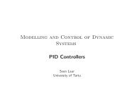
<strong>Lab</strong> <strong>5.5.1</strong>: <strong>Basic</strong> <strong>Spanning</strong> <strong>Tree</strong> <strong>Protocol</strong><br />
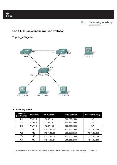
Topology Diagram<br />
Addressing Table<br />
Device<br />
(Hostname)<br />
Interface IP Address Subnet Mask Default Gateway<br />
S1 VLAN 1 172.17.10.1 255.255.255.0 N/A<br />
S2 VLAN 1 172.17.10.2 255.255.255.0 N/A<br />
S3 VLAN 1 172.17.10.3 255.255.255.0 N/A<br />
PC1 NIC 172.17.10.21 255.255.255.0 172.17.10.254<br />
PC2 NIC 172.17.10.22 255.255.255.0 172.17.10.254<br />
PC3 NIC 172.17.10.23 255.255.255.0 172.17.10.254<br />
PC4 NIC 172.17.10.27 255.255.255.0 172.17.10.254<br />
All contents are Copyright © 1992–2007 Cisco Systems, Inc. All rights reserved. This document is Cisco Public Information. Page 1 of 8
CCNA Exploration<br />
LAN Switching and Wireless: STP <strong>Lab</strong> <strong>5.5.1</strong>: <strong>Basic</strong> <strong>Spanning</strong> <strong>Tree</strong> <strong>Protocol</strong><br />
Learning Objectives<br />
Upon completion of this lab, you will be able to:<br />
• Cable a network according to the topology diagram<br />
• Erase the startup configuration and reload the default configuration, setting a switch to the default<br />
state<br />
• Perform basic configuration tasks on a switch<br />
• Observe and explain the default behavior of <strong>Spanning</strong> <strong>Tree</strong> <strong>Protocol</strong> (STP, 802.1D)<br />
• Observe the response to a change in the spanning tree topology<br />
Task 1: Perform <strong>Basic</strong> Switch Configurations<br />
Step 1: Cable a network that is similar to the one in the topology diagram.<br />
You can use any current switch in your lab as long as it has the required interfaces shown in the topology<br />
diagram. The output shown in this lab is based on Cisco 2960 switches. Other switch models may<br />
produce different output.<br />
Set up console connections to all three switches.<br />
Step 2: Clear any existing configurations on the switches.<br />
Clear NVRAM, delete the vlan.dat file, and reload the switches. Refer to <strong>Lab</strong> 2.5.1 for the procedure. After<br />
the reload is complete, use the show vlan privileged EXEC command to confirm that only default VLANs<br />
exist and that all ports are assigned to VLAN 1.<br />
S1#show vlan<br />
VLAN Name Status Ports<br />
---- -------------------------------- --------- -----------------------------<br />
1 default active Fa0/1, Fa0/2, Fa0/3, Fa0/4<br />
Fa0/5, Fa0/6, Fa0/7, Fa0/8<br />
Fa0/9, Fa0/10, Fa0/11, Fa0/12<br />
Fa0/13, Fa0/14, Fa0/15,Fa0/16<br />
Fa0/17, Fa0/18, Fa0/19,Fa0/20<br />
Fa0/21, Fa0/22, Fa0/23,Fa0/24<br />
Gig0/1, Gig0/2<br />
1002 fddi-default active<br />
1003 token-ring-default active<br />
1004 fddinet-default active<br />
1005 trnet-default active<br />
Step 3: Configure basic switch parameters.<br />
Configure the S1, S2, and S3 switches according to the following guidelines:<br />
• Configure the switch hostname.<br />
• Disable DNS lookup.<br />
• Configure an EXEC mode password of class.<br />
All contents are Copyright © 1992–2007 Cisco Systems, Inc. All rights reserved. This document is Cisco Public Information. Page 2 of 8
CCNA Exploration<br />
LAN Switching and Wireless: STP <strong>Lab</strong> <strong>5.5.1</strong>: <strong>Basic</strong> <strong>Spanning</strong> <strong>Tree</strong> <strong>Protocol</strong><br />
• Configure a password of cisco for console connections.<br />
• Configure a password of cisco for vty connections.<br />
(Output for S1 shown)<br />
Switch>enable<br />
Switch#configure terminal<br />
Enter configuration commands, one per line. End with CNTL/Z.<br />
Switch(config)#hostname S1<br />
S1(config)#enable secret class<br />
S1(config)#no ip domain-lookup<br />
S1(config)#line console 0<br />
S1(config-line)#password cisco<br />
S1(config-line)#login<br />
S1(config-line)#line vty 0 15<br />
S1(config-line)#password cisco<br />
S1(config-line)#login<br />
S1(config-line)#end<br />
%SYS-5-CONFIG_I: Configured from console by console<br />
S1#copy running-config startup-config<br />
Destination filename [startup-config]?<br />
Building configuration...<br />
[OK]<br />
Task 2: Prepare the Network<br />
Step 1: Disable all ports by using the shutdown command.<br />
Ensure that the initial switch port states are inactive with the shutdown command. Use the interfacerange<br />
command to simplify this task.<br />
S1(config)#interface range fa0/1-24<br />
S1(config-if-range)#shutdown<br />
S1(config-if-range)#interface range gi0/1-2<br />
S1(config-if-range)#shutdown<br />
S2(config)#interface range fa0/1-24<br />
S2(config-if-range)#shutdown<br />
S2(config-if-range)#interface range gi0/1-2<br />
S2(config-if-range)#shutdown<br />
S3(config)#interface range fa0/1-24<br />
S3(config-if-range)#shutdown<br />
S3(config-if-range)#interface range gi0/1-2<br />
S3(config-if-range)#shutdown<br />
Step 2: Re-enable the user ports on S1 and S2 in access mode.<br />
Refer to the topology diagram to determine which switch ports on S2 are activated for end-user device<br />
access. These three ports will be configured for access mode and enabled with the no shutdown<br />
command.<br />
S1(config)#interface fa0/3<br />
S1(config-if)#switchport mode access<br />
S1(config-if)#no shutdown<br />
S2(config)#interface range fa0/6, fa0/11, fa0/18<br />
All contents are Copyright © 1992–2007 Cisco Systems, Inc. All rights reserved. This document is Cisco Public Information. Page 3 of 8
CCNA Exploration<br />
LAN Switching and Wireless: STP <strong>Lab</strong> <strong>5.5.1</strong>: <strong>Basic</strong> <strong>Spanning</strong> <strong>Tree</strong> <strong>Protocol</strong><br />
S2(config-if-range)#switchport mode access<br />
S2(config-if-range)#no shutdown<br />
Step 3: Enable trunk ports on S1, S2, and S3<br />
Only a single VLAN is being used in this lab. However trunking has been enabled on all links<br />
between switches to allow for additional VLANs to be added in the future.<br />
S1(config-if-range)#interface range fa0/1, fa0/2<br />
S1(config-if-range)#switchport mode trunk<br />
S1(config-if-range)#no shutdown<br />
S2(config-if-range)#interface range fa0/1, fa0/2<br />
S2(config-if-range)#switchport mode trunk<br />
S2(config-if-range)#no shutdown<br />
S3(config-if-range)#interface range fa0/1, fa0/2<br />
S3(config-if-range)#switchport mode trunk<br />
S3(config-if-range)#no shutdown<br />
Step 4: Configure the management interface address on all three switches.<br />
S1(config)#interface vlan1<br />
S1(config-if)#ip address 172.17.10.1 255.255.255.0<br />
S1(config-if)#no shutdown<br />
S2(config)#interface vlan1<br />
S2(config-if)#ip address 172.17.10.2 255.255.255.0<br />
S2(config-if)#no shutdown<br />
S3(config)#interface vlan1<br />
S3(config-if)#ip address 172.17.10.3 255.255.255.0<br />
S3(config-if)#no shutdown<br />
Verify that the switches are correctly configured by pinging between them. From S1, ping the<br />
management interface on S2 and S3. From S2, ping the management interface on S3.<br />
Were the pings successful? ___________________________________________<br />
If not, troubleshoot the switch configurations and try again.<br />
Task 3: Configure Host PCs<br />
Configure the Ethernet interfaces of PC1, PC2, PC3, and PC4 with the IP address, subnet mask, and<br />
gateway indicated in the addressing table at the beginning of the lab.<br />
Task 4: Configure <strong>Spanning</strong> <strong>Tree</strong><br />
Step 1: Examine the default configuration of 802.1D STP.<br />
On each switch, display the spanning tree table with the show spanning-tree command. Root selection<br />
varies depending on the BID of each switch in your lab resulting in varying outputs.<br />
S1#show spanning-tree<br />
VLAN0001<br />
All contents are Copyright © 1992–2007 Cisco Systems, Inc. All rights reserved. This document is Cisco Public Information. Page 4 of 8
CCNA Exploration<br />
LAN Switching and Wireless: STP <strong>Lab</strong> <strong>5.5.1</strong>: <strong>Basic</strong> <strong>Spanning</strong> <strong>Tree</strong> <strong>Protocol</strong><br />
<strong>Spanning</strong> tree enabled protocol ieee<br />
Root ID Priority 32769<br />
Address 0019.068d.6980 This is the MAC address of the root switch<br />
This bridge is the root<br />
Hello Time 2 sec Max Age 20 sec Forward Delay 15 sec<br />
Bridge ID Priority 32769 (priority 32768 sys-id-ext 1)<br />
Address 0019.068d.6980<br />
Hello Time 2 sec Max Age 20 sec Forward Delay 15 sec<br />
Aging Time 300<br />
Interface Role Sts Cost Prio.Nbr Type<br />
---------------- ---- --- --------- -------- --------------------------------<br />
Fa0/1 Desg FWD 19 128.3 P2p<br />
Fa0/2 Desg FWD 19 128.4 P2p<br />
Fa0/3 Desg FWD 19 128.5 P2p<br />
S2#show spanning-tree<br />
VLAN0001<br />
<strong>Spanning</strong> tree enabled protocol ieee<br />
Root ID Priority 32769<br />
Address 0019.068d.6980<br />
Cost 19<br />
Port 1 (FastEthernet0/1)<br />
Hello Time 2 sec Max Age 20 sec Forward Delay 15 sec<br />
Bridge ID Priority 32769 (priority 32768 sys-id-ext 1)<br />
Address 001b.0c68.2080<br />
Hello Time 2 sec Max Age 20 sec Forward Delay 15 sec<br />
Aging Time 300<br />
Interface Role Sts Cost Prio.Nbr Type<br />
---------------- ---- --- --------- -------- --------------------------------<br />
Fa0/1 Root FWD 19 128.1 P2p<br />
Fa0/2 Desg FWD 19 128.2 P2p<br />
Fa0/6 Desg FWD 19 128.6 P2p<br />
Fa0/11 Desg FWD 19 128.11 P2p<br />
Fa0/18 Desg FWD 19 128.18 P2p<br />
S3#show spanning-tree<br />
VLAN0001<br />
<strong>Spanning</strong> tree enabled protocol ieee<br />
Root ID Priority 32769<br />
Address 0019.068d.6980<br />
Cost 19<br />
Port 1 (FastEthernet0/1)<br />
Hello Time 2 sec Max Age 20 sec Forward Delay 15 sec<br />
Bridge ID Priority 32769 (priority 32768 sys-id-ext 1)<br />
Address 001b.5303.1700<br />
Hello Time 2 sec Max Age 20 sec Forward Delay 15 sec<br />
Aging Time 300<br />
All contents are Copyright © 1992–2007 Cisco Systems, Inc. All rights reserved. This document is Cisco Public Information. Page 5 of 8
CCNA Exploration<br />
LAN Switching and Wireless: STP <strong>Lab</strong> <strong>5.5.1</strong>: <strong>Basic</strong> <strong>Spanning</strong> <strong>Tree</strong> <strong>Protocol</strong><br />
Interface Role Sts Cost Prio.Nbr Type<br />
---------------- ---- --- --------- -------- --------------------------------<br />
Fa0/1 Root FWD 19 128.1 P2p<br />
Fa0/2 Altn BLK 19 128.2 P2p<br />
Step 2: Examine the output.<br />
The bridge identifier (bridge ID), stored in the spanning tree BPDU consists of the bridge priority, the system ID<br />
extension, and the MAC address. The combination or addition of the bridge priority and the system ID<br />
extension are known as the bridge ID priority. The system ID extension is always the number of the VLAN.<br />
For example, the system ID extension for VLAN 100 is 100. Using the default bridge priority value of 32768, the<br />
bridge ID priority for VLAN 100 would be 32868 (32768 + 100).<br />
The show spanning-tree command displays the value of bridge ID priority. Note: The “priority” value<br />
within the parentheses represents the bridge priority value, which is followed by the value of the system ID<br />
extension.<br />
Answer the following questions based on the output.<br />
1. What is the bridge ID priority for switches S1, S2, and S3 on VLAN 1?<br />
a. S1 _______<br />
b. S2 _______<br />
c. S3 _______<br />
2. Which switch is the root for the VLAN 1 spanning tree? ________________<br />
3. On S1, which spanning tree ports are in the blocking state on the root switch?<br />
_________________<br />
4. On S3, which spanning tree port is in the blocking state? _________<br />
5. How does STP elect the root switch? _________________________<br />
6. Since the bridge priorities are all the same, what else does the switch use to determine the root?<br />
________________________<br />
Task 5: Observe the response to the topology change in 802.1D STP<br />
Now let's observe what happens when we intentionally simulate a broken link<br />
Step 1: Place the switches in spanning tree debug mode using the command debug spanningtree<br />
events<br />
S1#debug spanning-tree events<br />
<strong>Spanning</strong> <strong>Tree</strong> event debugging is on<br />
S2#debug spanning-tree events<br />
<strong>Spanning</strong> <strong>Tree</strong> event debugging is on<br />
S3#debug spanning-tree events<br />
<strong>Spanning</strong> <strong>Tree</strong> event debugging is on<br />
Step 2: Intentionally shutdown port Fa0/1 on S1<br />
All contents are Copyright © 1992–2007 Cisco Systems, Inc. All rights reserved. This document is Cisco Public Information. Page 6 of 8
CCNA Exploration<br />
LAN Switching and Wireless: STP <strong>Lab</strong> <strong>5.5.1</strong>: <strong>Basic</strong> <strong>Spanning</strong> <strong>Tree</strong> <strong>Protocol</strong><br />
S1(config)#interface fa0/1<br />
S1(config-if)#shutdown<br />
Step 3: Record the debug output from S2 and S3<br />
S2#<br />
1w2d: STP: VLAN0001 we are the spanning tree root<br />
S2#<br />
1w2d: %LINEPROTO-5-UPDOWN: Line protocol on Interface FastEthernet0/1,<br />
changed state to down<br />
1w2d: %LINK-3-UPDOWN: Interface FastEthernet0/1, changed state to down<br />
S2#<br />
1w2d: STP: VLAN0001 heard root 32769-0019.068d.6980 on Fa0/2<br />
1w2d: supersedes 32769-001b.0c68.2080<br />
1w2d: STP: VLAN0001 new root is 32769, 0019.068d.6980 on port Fa0/2, cost 38<br />
1w2d: STP: VLAN0001 sent Topology Change Notice on Fa0/2<br />
S3#<br />
1w2d: STP: VLAN0001 heard root 32769-001b.0c68.2080 on Fa0/2<br />
1w2d: STP: VLAN0001 Fa0/2 -> listening<br />
S3#<br />
1w2d: STP: VLAN0001 Topology Change rcvd on Fa0/2<br />
1w2d: STP: VLAN0001 sent Topology Change Notice on Fa0/1<br />
S3#<br />
1w2d: STP: VLAN0001 Fa0/2 -> learning<br />
S3#<br />
1w2d: STP: VLAN0001 sent Topology Change Notice on Fa0/1<br />
1w2d: STP: VLAN0001 Fa0/2 -> forwarding<br />
When the link from S2 that is connected to the root switch goes down, what is its initial conclusion about<br />
the spanning tree root?______________________<br />
Once S2 receives new information on Fa0/2, what new conclusion does it draw?____________________<br />
Port Fa0/2 on S3 was previously in a blocking state before the link between S2 and S1 went down. What<br />
states does it go through as a result of the topology change? __________________________________<br />
Step 4: Examine what has changed in the spanning tree topology using the show spanningtree<br />
command<br />
S2#show spanning-tree<br />
VLAN0001<br />
<strong>Spanning</strong> tree enabled protocol ieee<br />
Root ID Priority 32769<br />
Address 0019.068d.6980<br />
Cost 38<br />
Port 2 (FastEthernet0/2)<br />
Hello Time 2 sec Max Age 20 sec Forward Delay 15 sec<br />
Bridge ID Priority 32769 (priority 32768 sys-id-ext 1)<br />
Address 001b.0c68.2080<br />
Hello Time 2 sec Max Age 20 sec Forward Delay 15 sec<br />
Aging Time 300<br />
All contents are Copyright © 1992–2007 Cisco Systems, Inc. All rights reserved. This document is Cisco Public Information. Page 7 of 8
CCNA Exploration<br />
LAN Switching and Wireless: STP <strong>Lab</strong> <strong>5.5.1</strong>: <strong>Basic</strong> <strong>Spanning</strong> <strong>Tree</strong> <strong>Protocol</strong><br />
Interface Role Sts Cost Prio.Nbr Type<br />
---------------- ---- --- --------- -------- --------------------------------<br />
Fa0/2 Root FWD 19 128.2 P2p<br />
Fa0/6 Desg FWD 19 128.6 P2p<br />
Fa0/11 Desg FWD 19 128.11 P2p<br />
Fa0/18 Desg FWD 19 128.18 P2p<br />
S3#show spanning-tree<br />
VLAN0001<br />
<strong>Spanning</strong> tree enabled protocol ieee<br />
Root ID Priority 32769<br />
Address 0019.068d.6980<br />
Cost 19<br />
Port 1 (FastEthernet0/1)<br />
Hello Time 2 sec Max Age 20 sec Forward Delay 15 sec<br />
Bridge ID Priority 32769 (priority 32768 sys-id-ext 1)<br />
Address 001b.5303.1700<br />
Hello Time 2 sec Max Age 20 sec Forward Delay 15 sec<br />
Aging Time 300<br />
Interface Role Sts Cost Prio.Nbr Type<br />
---------------- ---- --- --------- -------- --------------------------------<br />
Fa0/1 Root FWD 19 128.1 P2p<br />
Fa0/2 Desg FWD 19 128.2 P2p<br />
Answer the following questions based on the output.<br />
1. What has changed about the way that S2 forwards traffic? __________________________________<br />
2. What has changed about the way that S3 forwards traffic?___________________________________<br />
All contents are Copyright © 1992–2007 Cisco Systems, Inc. All rights reserved. This document is Cisco Public Information. Page 8 of 8