Paper Title - Chandra X-Ray Observatory (CXC)
Paper Title - Chandra X-Ray Observatory (CXC)
Paper Title - Chandra X-Ray Observatory (CXC)

You also want an ePaper? Increase the reach of your titles
YUMPU automatically turns print PDFs into web optimized ePapers that Google loves.
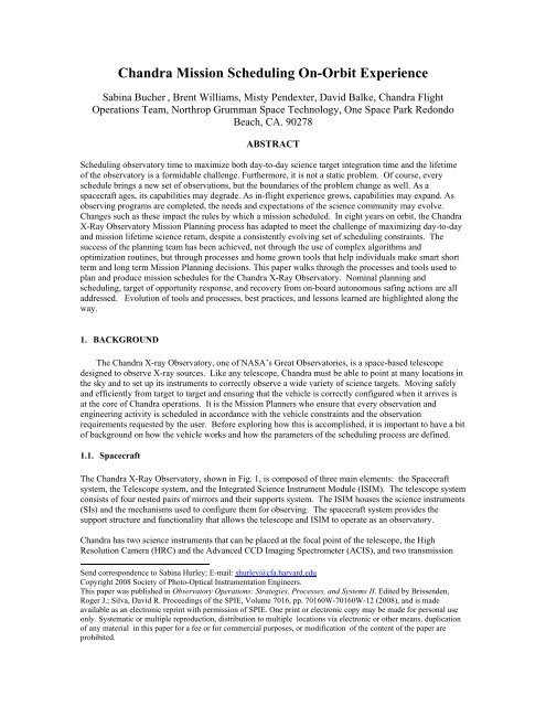
<strong>Chandra</strong> Mission Scheduling On-Orbit Experience<br />
Sabina Bucher *, Brent Williams, Misty Pendexter, David Balke, <strong>Chandra</strong> Flight<br />
Operations Team, Northrop Grumman Space Technology, One Space Park Redondo<br />
Beach, CA. 90278<br />
ABSTRACT<br />
Scheduling observatory time to maximize both day-to-day science target integration time and the lifetime<br />
of the observatory is a formidable challenge. Furthermore, it is not a static problem. Of course, every<br />
schedule brings a new set of observations, but the boundaries of the problem change as well. As a<br />
spacecraft ages, its capabilities may degrade. As in-flight experience grows, capabilities may expand. As<br />
observing programs are completed, the needs and expectations of the science community may evolve.<br />
Changes such as these impact the rules by which a mission scheduled. In eight years on orbit, the <strong>Chandra</strong><br />
X-<strong>Ray</strong> <strong>Observatory</strong> Mission Planning process has adapted to meet the challenge of maximizing day-to-day<br />
and mission lifetime science return, despite a consistently evolving set of scheduling constraints. The<br />
success of the planning team has been achieved, not through the use of complex algorithms and<br />
optimization routines, but through processes and home grown tools that help individuals make smart short<br />
term and long term Mission Planning decisions. This paper walks through the processes and tools used to<br />
plan and produce mission schedules for the <strong>Chandra</strong> X-<strong>Ray</strong> <strong>Observatory</strong>. Nominal planning and<br />
scheduling, target of opportunity response, and recovery from on-board autonomous safing actions are all<br />
addressed. Evolution of tools and processes, best practices, and lessons learned are highlighted along the<br />
way.<br />
1. BACKGROUND<br />
The <strong>Chandra</strong> X-ray <strong>Observatory</strong>, one of NASA’s Great Observatories, is a space-based telescope<br />
designed to observe X-ray sources. Like any telescope, <strong>Chandra</strong> must be able to point at many locations in<br />
the sky and to set up its instruments to correctly observe a wide variety of science targets. Moving safely<br />
and efficiently from target to target and ensuring that the vehicle is correctly configured when it arrives is<br />
at the core of <strong>Chandra</strong> operations. It is the Mission Planners who ensure that every observation and<br />
engineering activity is scheduled in accordance with the vehicle constraints and the observation<br />
requirements requested by the user. Before exploring how this is accomplished, it is important to have a bit<br />
of background on how the vehicle works and how the parameters of the scheduling process are defined.<br />
1.1. Spacecraft<br />
The <strong>Chandra</strong> X-<strong>Ray</strong> <strong>Observatory</strong>, shown in Fig. 1, is composed of three main elements: the Spacecraft<br />
system, the Telescope system, and the Integrated Science Instrument Module (ISIM). The telescope system<br />
consists of four nested pairs of mirrors and their supports system. The ISIM houses the science instruments<br />
(SIs) and the mechanisms used to configure them for observing. The spacecraft system provides the<br />
support structure and functionality that allows the telescope and ISIM to operate as an observatory.<br />
<strong>Chandra</strong> has two science instruments that can be placed at the focal point of the telescope, the High<br />
Resolution Camera (HRC) and the Advanced CCD Imaging Spectrometer (ACIS), and two transmission<br />
Send correspondence to Sabina Hurley; E-mail: shurley@cfa.harvard.edu<br />
Copyright 2008 Society of Photo-Optical Instrumentation Engineers.<br />
This paper was published in <strong>Observatory</strong> Operations: Strategies, Processes, and Systems II. Edited by Brissenden,<br />
Roger J.; Silva, David R. Proceedings of the SPIE, Volume 7016, pp. 70160W-70160W-12 (2008), and is made<br />
available as an electronic reprint with permission of SPIE. One print or electronic copy may be made for personal use<br />
only. Systematic or multiple reproduction, distribution to multiple locations via electronic or other means, duplication<br />
of any material in this paper for a fee or for commercial purposes, or modification of the content of the paper are<br />
prohibited.
grating arrays (OTGs) which can be flipped into the path of the X-rays to provide spectroscopy data. The<br />
SIs are sensitive detectors and susceptible to damage from the radiation environment. Therefore an onboard<br />
radiation sensor, EPHIN, is used to detect elevated radiation rates and stow the instruments when<br />
rates reach pre-determined levels. ACIS and HRC are located on the Science Instrument Module (SIM),<br />
which is translated to position the specified instrument at the focal point and also provides focus<br />
adjustments. Each observation requires a specific instrument, translation position, focus position and<br />
grating, each of which is specified in a strictly formatted Observation Request (OR).<br />
The OR also specifies the<br />
precise location of the<br />
observation target so that<br />
the observatory can be<br />
slewed to the correct<br />
position. Pointing of the<br />
observatory is provided by<br />
the Pointing Control and<br />
Aspect Determination<br />
(PCAD) subsystem. The<br />
PCAD subsystem system<br />
has gyros, an aspect<br />
camera, sun sensors, and<br />
reaction wheels to monitor<br />
and control where the<br />
telescope is pointing at any<br />
given moment. During<br />
observations the Aspect Fig. 1. <strong>Chandra</strong> Spacecraft<br />
Camera Assembly (ACA)<br />
is used to track stars and fiducial lights (point sources fixed in the spacecraft body frame), which are used<br />
to provide a highly accurate pointing solution. The reaction wheels are used to orient the vehicle, maintain<br />
pointing and store accumulated angular momentum. Small thrusters are used to unload angular momentum<br />
from the reaction wheels as required. Gyros provide spacecraft rate data which is used to control the<br />
motion of the vehicle. The sun sensors provide <strong>Chandra</strong> with autonomous pointing control capability,<br />
which, when particular faults are detected, will bring <strong>Chandra</strong> to a safe attitude.<br />
A spacecraft cannot operate without power, and <strong>Chandra</strong>'s electrical power comes from two solar array<br />
wings. The energy generated is distributed by the Electrical Power Subsystem (EPS), which also provides<br />
three banks of batteries to provide power during eclipses. <strong>Chandra</strong> goes through two earth eclipse seasons<br />
annually and also experiences occasional lunar eclipses.<br />
To keep the instruments and spacecraft components operating correctly and the telescope alignment<br />
sufficiently accurate, temperatures on <strong>Chandra</strong> must be well controlled. The thermal subsystem uses<br />
several of methods to provide this control. Cooling radiators, insulation, heaters, thermostats, and reflective<br />
surfaces are used to keep each component within its specified thermal limits. As the spacecraft has aged<br />
the efficacy of the multi-layer insulation (MLI) for keeping unit temperatures stable and within limits has<br />
degraded. More specifically, the sun-side of the vehicle has warmed over time, causing exposed units on<br />
the sun side to near or exceed their maximum operating temperatures. To control temperatures, the sun<br />
exposure of these units must be limited. As the angle between the Sun and the spacecraft changes units<br />
receive more or less direct sunlight, depending on their position. So thermal control of several units on<br />
<strong>Chandra</strong> is now closely tied to sun angle.<br />
Linking all of these subsystems and components together is the communications, control, and data<br />
management (CCDM) system. It provides transmit and receive capability through two low gain antennas,<br />
receives and processes commands from the ground and from the on-board computer (OBC), collects and<br />
distributes measurements from sensors, and stores data to two solid state recorders (SSRs). The Deep<br />
Space Network (DSN) is used to communicate with <strong>Chandra</strong>. Generally three one-hour tracks a day
provide opportunities to confirm the vehicle state of health, to uplink new command products and to dump<br />
the data stored on the SSR to the ground.<br />
1.2. Constraints<br />
Each instrument and subsystem has rules by which it must be operated. Furthermore, there are system level<br />
rules designed to protect the vehicle as a whole. Before launch these rules were documented in a<br />
constraints and restrictions document (CARD). With on-orbit experience some of the constraints in the<br />
CARD could be relaxed or eliminated. As the vehicle has aged new constraints have become necessary.<br />
Since not all vehicle constraints impact mission scheduling and since the CARD was designed for<br />
engineers, not schedulers, a second constraint document, the Mission Planning Guidelines, was created<br />
several years into the mission. This document provides the schedulers with a prioritized list of the rules and<br />
implementations they must make their scheduling decisions by. It is a living document and is frequently<br />
updated. To improve flexibility and accessibility the Mission Planning Guidelines have been recently<br />
ported from a single document into a TWiki web. The Revision Control System built into TWiki provides<br />
adequate configuration management for a controlled document. The TWiki web, hosted on the <strong>Chandra</strong><br />
Operations Control Center (OCC) website, allows linking between the guidelines, the CARD, and reference<br />
materials and provides a widely accessible, platform independent means for viewing the guidelines. The<br />
guidelines are now the primary source for information on vehicle constraints that impact scheduling.<br />
Although one generally thinks of constraints as flight rules for the spacecraft, they are not limited to how<br />
the vehicle is operated. In that each observation has specified parameters that determine how it is<br />
scheduled; each observation is itself a set of constraints. Some observations only define where the vehicle<br />
must point, for how long and which SI must be used. Other observations have exact timing constraints, roll<br />
angle requirements, or coordinations. Constraints that restrict how and when an observation is scheduled<br />
are specified in the same OR that defines the pointing and instrument configuration for the observation.<br />
The combination of vehicle and observation constraints creates a constraint space, which is constantly<br />
evolving. Thermal constraints change with time and with season, the radiation zones evolve with the orbit,<br />
restrictions on use of consumables become increasingly difficult to meet with mission extension and<br />
observation constraints become more complex as observers gain experience using <strong>Chandra</strong>. To date,<br />
<strong>Chandra</strong> has had no mission impacting unit failures, but unit failure could also impact the constraint space.<br />
The table below provides a summary of the current scheduling constraints that <strong>Chandra</strong> Mission Planners<br />
work within for every schedule.<br />
Table 1. <strong>Chandra</strong> Constraint Summary<br />
Science<br />
Attitude<br />
Thermal<br />
Consumabl<br />
es<br />
Target, Window, Phase, Roll, Coordination, and Target of Opportunity turnaround time<br />
all dictate when an observation can be scheduled and how difficult it is to schedule.<br />
Except for target, any of these can also be specified as a preference, which is less<br />
restrictive than a constraint.<br />
Sun position constraints, planetary and bright X-<strong>Ray</strong> source avoidance, and star quality<br />
requirements all impact when an observation can be scheduled.<br />
EPHIN temperatures, Propulsion Line temperatures, thruster temperatures and ACIS<br />
Power Supply temperatures all impact if and when an observation can be scheduled. The<br />
temperatures of these units are now dominated by sun exposure, which turns thermal<br />
constraints into time at sun angle (attitude) constraints.<br />
Minimizing number of momentum unloads and SIM moves do not currently drive<br />
scheduling, but if ignored entirely may become increasingly important<br />
Radiation Radiation Zones determine the time in any given orbit that can be used for observations
The mission planning system delivered at launch, the Offline System (OFLS) was designed to schedule all<br />
observations in accordance with the CARD and with constraints specified in the OR. However, very soon<br />
after launch, things started to change. Within the first few orbits of science operations, ACIS started<br />
incurring damage from low energy protons. This observed damage led to a new scheduling constraint that<br />
was not anticipated before launch, and, therefore, not incorporated into the ground system. Later followed<br />
changes to, among other items, scheduling of OTG moves, restrictions to the number of momentum<br />
unloads allowed and restrictions on the temperatures of various units. Each constraint change required an<br />
adjustment to the way the mission was scheduled. The <strong>Chandra</strong> scheduling process, therefore, by<br />
necessity, became adaptable and flexible.<br />
While the precise issues facing <strong>Chandra</strong> are not likely to re-occur on other missions, most spacecraft will<br />
reach a point where they must be operated by a new and changing set of rules. This paper will walk<br />
through the <strong>Chandra</strong> scheduling process, highlighting lessons learned and best practices that could aid other<br />
missions in preparing for the inevitable parameter space change caused by vehicle age, on-orbit experience,<br />
environmental exposure, and changing resources and expectations.<br />
2. Nominal Mission Scheduling Process<br />
2.1. Process Overview and Goals<br />
<strong>Chandra</strong> mission scheduling is performed on a week by week basis. Each weekly schedule includes all of<br />
the maneuver and reconfiguration commanding required to perform each observation and to safely stow the<br />
instruments when passage through the Van Allen belts makes the radiation environment too hostile to<br />
observe. Responsibility for mission scheduling is spilt between Science Operations Team (SOT) and Flight<br />
Operations Team (FOT) Mission Planners. FOT Mission Planning performs the detailed level scheduling<br />
that that turns an unordered list of observations into a weekly observing schedule and finally command<br />
loads. This detailed level scheduling will be the focus of this paper.<br />
The detailed scheduling process aims to generate optimal schedules for <strong>Chandra</strong> that meet all spacecraft<br />
health and safety constraints, meet science constraints of the observations and respect preferences of<br />
observers as much as possible. <strong>Chandra</strong> mission scheduling takes a heuristic approach to solving the<br />
problem of optimizing observing schedules. Schedules are manually ordered using the follow list of<br />
priorities: (1) Spacecraft Safety, (2) Science Goals, (3) Maximize Time for Science, (4) Minimize use of<br />
consumables. <strong>Chandra</strong> is fortunate in that at their current rate of use consumables will last beyond the<br />
planned duration of the mission, so use of consumables can be prioritized below science objectives.<br />
2.2. Process Description<br />
Every year, once the call for proposals is complete and the peer review process recommends targets for<br />
observation, approved observations are translated into ORs. The ORs are laid out into a yearly observing<br />
plan, binned by week. This yearly plan is called the Long Term Schedule (LTS). Layout of the LTS is the<br />
first step toward generating efficient weekly schedules. First, the observations that are short and have no<br />
observing constraints are pulled out into the “pool”. Pool targets are not assigned to any given week, but<br />
are instead used to fill in around constrained and long observations, improving efficiency. All remaining<br />
observations are placed into a particular week of the year, based on science constraints specified in the OR<br />
and on availability of the specified target within vehicle constraints during that week.<br />
Each week the targets scheduled in the LTS are put into an OR list that is delivered to the Flight Operations<br />
Team (FOT) Mission Planners. FOT Mission Planning then performs the detailed scheduling that turns an<br />
unordered list of observations into a weekly observing schedule and finally command loads. The mission<br />
scheduling software provided to the FOT Mission Planners at launch was designed as a “black box” that<br />
could ingest ORs and Engineering Requests (ERs) and output efficient mission schedules. An optimization<br />
routine with knowledge of spacecraft and observation constraints would do most of the work of mission
scheduling. In practice, the optimization routine did not generally produce desirable results. Furthermore,<br />
on-orbit experience quickly led to new scheduling constraints that were not anticipated before launch, and,<br />
therefore, not incorporated into the optimization routine. So, while each new constraint was incorporated<br />
into the scheduling software, building safe and efficient schedules required manual intervention.<br />
Unfortunately, a lack of visibility into the software made manually assembling a useable mission schedule<br />
an exercise in trial and error and thus an extremely inefficient process. To remedy the problem, the FOT<br />
designed and developed a stand alone, GUI based, tool, the ORViewer, that reads in observation and<br />
attitude requests and displays them in several frames of reference. Fig. 2 provides a snap of the ORViewer<br />
GUI. The displays allow the scheduler to visualize the attitudes required for the week and to assemble a<br />
sequence of maneuvers and dwells (an attitude profile) through an interactive timeline view. An efficiency<br />
view allows the scheduler to immediately assess the impact of schedule changes on efficiency. The<br />
ORViewer also allows adding in ERs, which schedule activities required for spacecraft maintenance and<br />
other non-science related activities. As requested, the ORViewer pushes the attitude profile to a second,<br />
home grown tool, the Maneuver Constraint Checker (MCC). MCC displays the attitude profile with<br />
respect to various scheduling constraints, providing visual feedback of the impact of schedule changes on<br />
each constraint. The schedulers move back and forth between ORViewer and MCC until they have<br />
assembled an attitude profile that meets all vehicle constraints and efficiently moves through all of the<br />
observations planned for the week. These two tools remain a very important part of <strong>Chandra</strong> mission<br />
scheduling processing and ordering the OR list using them is first step in assembling a schedule.<br />
Fig. 2. ORViewer scheduling tool graphical interface. Each panel can be toggled to display different views of the<br />
schedule. Constraint displays can be toggled on and off to provide maximum capability without visual clutter.<br />
Scheduling is achieved through context menus in the timeline and remaining request panels.<br />
Once the ORs and ERs are assembled into a weekly schedule they are linked together and put into the<br />
OFLS scheduling routine. Linking puts the observations into a single chain, so that the optimization<br />
routine’s algorithm only has one solution; the one designed by the scheduler. It may seem odd to pass an<br />
optimization routine a solved problem, but the routine is central to the design of the OFLS scheduling<br />
software and cannot be disabled. The OFLS scheduling software currently provides the only algorithm with<br />
knowledge of all of the exact timing and commanding requirements used to build safe mission schedules.<br />
So, by necessity, it is used to build command products from an assembled schedule. Unfortunately, linking
observations together is not guaranteed to force the optimization routine to schedule observations as<br />
requested. The mission schedulers, therefore, do a fair amount of troubleshooting, trying to get the<br />
optimization routine to return a schedule that matches the observing plan laid out in the ORViewer.<br />
Once the OFLS schedule is successfully replicating the observing plan laid out in the ORViewer, the<br />
schedule products are passed to an external algorithm for star selection. The OFLS scheduling software<br />
identifies candidate guide stars for observations before scheduling them, and only schedules observations<br />
its algorithm determines have adequate stars. With the original settings, this algorithm disallowed many<br />
observations. Clearly, approved observations need to be observed and should only be disallowed as a last<br />
resort, so the star selection parameters were relaxed to allow observations to schedule. The relaxation had<br />
the unfortunate side effect of producing catalogs with insufficient stars for accurate aspect reconstruction<br />
and, sometimes, for adequate attitude reference. Initially, unacceptable catalogs were edited by hand, with<br />
ACA engineers hand selecting desirable stars and mission planners editing them into command products.<br />
Over time the process was automated into tools and scripts. Finally, a working group of PCAD and ACA<br />
Engineers and Mission Planners defined a star selection algorithm that shifted the way star selection was<br />
performed. It assumed that an adequate catalog would be found for all observations, and accepted the risk<br />
of a re-schedule if one could not be. The algorithm was coded into a stand alone tool, the Simple AXAF<br />
User Select Acquisition and Guide star Editor (SAUSAGE), that would be used to replace every star<br />
catalog used in mission schedules. SAUSAGE also provided a GUI interface for viewing and editing star<br />
catalogs. The tool is used to this day and observations are very rarely rescheduled due to poor quality star<br />
catalogs.<br />
Once<br />
stars have been replaced the schedule products are used to generate command products, which can be<br />
uplinked to the spacecraft. The scheduling software and the command load generation software have a<br />
single interface, the Detailed Operations Timeline (DOT). The DOT is simply a formatted text file, so it<br />
can be easily modified. The DOT is what allows replacement of star catalogs after the fact and provides a<br />
means for mission schedulers to correct small scheduling problems by hand. While hand editing schedules<br />
is not desirable, it provides ultimate flexibility. This flexibility has proven to be a necessity in efficiently<br />
generating mission schedules. The command load generation software processes the DOT and uses<br />
predefined command sequences to generate command loads.<br />
Once<br />
the schedule has been made into command loads, the schedule and command products are packaged<br />
for review. The review package is ingested by a suite of independently developed and maintained set of<br />
Perl scripts, Backstop, that reverse engineer the command loads into command mnemonics and time-tags.<br />
The resulting report is processed and reviewed by each subsystem, both science instrument teams and<br />
science mission planning. Each reviewer reports back to the FOT Mission Planning Manager identifying<br />
any problems detected in the loads or approving the load set. Once review comments have been received<br />
from every review team, problems are addressed by rescheduling or by editing the DOT and new command<br />
loads are generated. The new command loads go through the same review process until no problems are<br />
reported. Once every reviewer has approved the load set they are approved by the FOT Mission Planning<br />
Manager and Flight Director. Approved command loads are saved into a database, which enables the<br />
spacecraft controllers to uplink them to the spacecraft.<br />
The<br />
scheduling process, from receipt of the OR list to command load uplink, takes approximately two and a<br />
half weeks to complete. The end-to-end process is summarized in Fig. 3. While the process may seem<br />
manual and labor intensive, it is highly effective and generally well controlled. An average of 93% of<br />
available science time is used for observations. New constraints or requests are incorporated quickly.<br />
Finally, when questions or problems arise the Mission Planner responsible for the week knows the details<br />
of every decision made in scheduling that week and can, therefore, respond more quickly and accurately.
Fig. 3. End to end <strong>Chandra</strong> mission scheduling process<br />
2.3. Process Controls:<br />
The two metrics that best monitor the performance of the scheduling process are: (1) effort required to<br />
generate a schedule, and (2) the efficiency of the schedule produced. While it is difficult to get accurate<br />
measurements of effort, efficiency is a simple calculation. The <strong>Chandra</strong> FOT computes and tracks schedule<br />
efficiency on a weekly basis and uses more qualitative measures of effort required to generate a schedule.<br />
Not surprisingly, effort and efficiency tend to track together. As schedules become harder to assemble,<br />
they also become less efficient. As Fig. 4 shows, schedule efficiency has a rather large standard deviation,<br />
but the mean was fairly consistent until 2004. In late 2004, efforts to protect the EPHIN radiation detector<br />
from getting too hot and the propulsion lines from getting too cold forced splitting observations into pieces<br />
with large maneuvers between them. The scheduling problem had become over-constrained and, as a result,<br />
the effort to schedule observations increased significantly and the availability of science targets and<br />
efficiency of schedules suffered. Clearly, the scheduling process was no longer well controlled.
Fig. 4. Weekly scheduling efficiency. Calculated by diving time spent observing science targets by time available<br />
for observing. Week to week variation largely due to OR list profile. Trends generally due to constraint<br />
migration.<br />
The decline in scheduling ability prompted cross-team analysis and discussion, which led to relaxation of<br />
the EPHIN temperature limits, which, in turn, allowed scheduling ability to recover. This cross-team group<br />
was the precursor to a new working group, the Mission Planning and Constraints Working Group<br />
(MPCWG). The mission of the MPCWG is to minimize the impact of constraints while protecting the<br />
safety of the vehicle. The group has representatives from mission planning, engineering, both SIs and<br />
project management. Since 2005, the group has been actively and effectively managing constraints and<br />
optimizing scheduling, which has kept scheduling efficiency near early mission values.<br />
While it is intuitive that if a constraint is relaxed, scheduling will get easier, it is not simple to discern how<br />
much impact a given relaxation will have. It may be that all of the work put into relaxing a constraint is for<br />
naught, because another constraint overwhelms scheduling in that part of the constraint space. To resolve<br />
this problem, the MPCWG developed a tool that can run all of the models used in scheduling and display<br />
the impact of constraint changes. Given a set of constraints and starting conditions, the tool generates a<br />
maximum allowed dwell time at every attitude in the sky. The user can set constraint thresholds, model<br />
parameters or output dates and regenerate maximum dwell times. Maximum dwell time correlates well to<br />
scheduling efficiency and target availability, since shorter allowed dwells forces splitting long observations<br />
into parts, which decreases target availability, and requires more maneuvering, which reduces efficiency.<br />
So measuring maximum allowed dwell time gives insight into scheduling ability, and generating a delta<br />
chart allows the user to see the impact of a constraint change. The tool can analyze the impact of given<br />
constraint over time, of a constraint relaxation or of a new constraint. This constraint integration tool has<br />
been fully incorporated into the <strong>Chandra</strong> constraint management process and is used to assess the impact of<br />
constraints over time and inform decisions regarding constraint relaxation versus scheduling efficiency. It<br />
also provides dwell time data that is now fed into the process of laying out the yearly observing plan. This<br />
predictive data maximizes the probability that all of the observations chosen for a given week will be able<br />
to be scheduled once that week arrives. Fig. 5 provides a sample output from the constraint integration<br />
routine.
Fig. 5. Maximum allowed dwell times by Ra and Dec for late 2007. Plot generated with constraint integration tool,<br />
which also outputs delimited text files for processing and import into other tools.<br />
3. Fast Turn-Around Scheduling<br />
3.1. Targets of Opportunity<br />
Target of Opportunity (TOO) observations can have requested turnaround times ranging from hours to<br />
months. Any TOO with a requested turnaround time greater than three weeks is incorporated into the<br />
nominal weekly scheduling process. For observations requested to occur within three weeks, extra effort is<br />
required to schedule them. If the load set where the TOO will be placed has not yet been uplinked to the<br />
spacecraft, the Mission Planner uses the ORViewer to incorporate the TOO into their observing plan and<br />
goes through the nominal scheduling process at an accelerated pace. The scheduler’s goal is to disturb as<br />
little of the original observing plan as possible, which minimizes the effort required to incorporate the TOO<br />
and the chance for introducing errors. However, when inserting a TOO observation, something must be<br />
removed from the schedule. ORs with time constraints or those coordinated with other observatories are<br />
removed only as a last resort. So the scheduler must balance keeping the schedule intact with ensuring that<br />
only unconstrained observations are removed. This is generally achieved through close coordination<br />
between flight team schedulers and science mission planners.<br />
If the requested turnaround time places the TOO observation within the week running on the spacecraft, the<br />
running loads must be interrupted and replaced with a new observing plan. Fast turn-around scheduling that<br />
replaces the running loads is referred to as a “re-plan”. In order to provide fast turnaround times, flight and<br />
science team schedulers are on-call 24 hours a day. An automated email system sends messages to pagers<br />
and cell phones alerting the planners to a fast turnaround re-plan. Science mission planning immediately<br />
starts to coordinate with the Director’s Office, science instrument teams and observer to finalize the<br />
parameters of the observation as quickly as possible. While this happens, flight mission planning takes the<br />
information they have (generally target and turn-around time) and generates a straw-man schedule.
Re-plans must take into account the requested turn around time, maneuvers required to reach the new<br />
target, spacecraft constraints, communications times and the time required to build and review a new set of<br />
products. Due to on-board memory allocation the weekly loads are divided into smaller load segments,<br />
generally lasting approximately a day and a half. Re-planning a running load segment requires stopping<br />
commanding, while it is running, and then re-planning it with new commanding. Once the running load<br />
segment has been stopped, there is no on-board commanding until a new load has been activated. Due to<br />
the slight increase in risk and the increased complexity of uplink, interrupting a running load segment is<br />
avoided whenever possible. To allow viewing all of the items that must be considered when re-planning in<br />
a single easy to use format, a graphical timeline of mission schedules is provided on the <strong>Chandra</strong> OCC<br />
website. The graphical timeline is used to give a snapshot view of the current and planned configurations<br />
of <strong>Chandra</strong> and the communications opportunities for uplink. The snapshot is used to find the first and last<br />
available uplink opportunities, load segment breaks, and to identify the lowest impact spot to place the<br />
TOO that still meets the requested turnaround. All of these items are considered when selecting the load<br />
interrupt time.<br />
Once the load interrupt time is identified, the flight scheduler begins to use the ORViewer and OFLS to<br />
generate the replacement TOO schedule. Scheduling usually begins before the observation parameters<br />
have been finalized. The planner uses a stand-in OR, filling in as much information is available at the time,<br />
to begin the scheduling process. Once all the parameters have been set, a final OR is delivered. Generally<br />
flight mission planning simply needs to re-run the software with the final parameters and perform the last<br />
few steps of the scheduling process when the final OR is delivered. If flight mission planning were to wait<br />
until all of the OR parameters were finalized to begin scheduling, the process would be delayed by hours.<br />
Once the re-planned schedule is complete it goes through the same review process as nominal weekly<br />
loads, again on an accelerated schedule. All reviewers are also on-call 24 hours a day and email messages<br />
are sent to pagers and cell phones indicating that a fast turn around review is required. Once the loads are<br />
approved, a Command Action Procedure, which directs the console operators to replace the running loads<br />
with the TOO loads, is generated, reviewed and executed.<br />
3.2. Safing Action Response<br />
<strong>Chandra</strong> is equipped with a cleverly designed safing subsystem. The flight software monitors for survival<br />
threatening conditions instead of specific unit failures. This system provides robust protection against unit<br />
failures, environmental changes and ground based errors. When the vehicle detects a survival threatening<br />
condition it takes a proportional response to safe the vehicle. Most safing actions safe the SIs and stop the<br />
running loads. Others add attitude safing by acquiring bright stars for guidance or by aligning the vehicle<br />
normal to the sun vector. The most drastic safing action, Safe Mode, swaps all core spacecraft units and<br />
uses a backup processor to bring the vehicle normal to the sun vector. Any safing action that stops the<br />
mission loads, requires mission planning response. A similar paging system to the one used for TOOs is<br />
used to alert engineers and mission planners when a safing action has occurred.<br />
Once the root cause for the safing action has been identified, any necessary recovery actions have been<br />
completed and the engineering team has confirmed that it is safe for the science mission to resume, mission<br />
planning begins to re-plan the weekly schedule. Generally, safing actions will cause some science<br />
observations to be missed. The re-plan must take skipped observations into account. First of all, when a<br />
safing action occurs and observations are missed, the configuration of the vehicle is not as expected by the<br />
original schedule. Continuity between the vehicle and the mission schedule must be re-established;<br />
therefore, the original plan cannot simply be restarted. Additionally, if an observation with a coordination<br />
or time constraint is missed all efforts should be made to reschedule that observation within its required<br />
window if safely possible. Rescheduling constrained observations, however, must be balanced with ease of<br />
resumption. As with TOO scheduling, the scheduler will aim to minimize changes to the original plan to<br />
minimize the effort required for the re-plan and the risk of introducing errors. With all these complicating<br />
factors, the graphical timeline, used to re-plan schedules for TOOs, is also a valuable resource in planning<br />
science resumption loads. Once the resumption plan is laid out and approved, and continuity is accounted<br />
for, science resumption scheduling follows the nominal scheduling process, at an accelerated rate.
When the mission loads are stopped, the planned attitude profile stops. As mentioned in Section 1, thermal<br />
control of several units on <strong>Chandra</strong> is now based on attitude. If the loads are stopped at the wrong attitude,<br />
the units can quickly get too hot or too cold. Additionally, planets can cross in front of the star tracker and<br />
angular momentum can accumulate quickly when an attitude is held for an unplanned period of time. If<br />
science cannot be resumed in time to avoid negative consequences of dwelling at an unplanned attitude a<br />
“maneuver only” load must be generated and uplinked. Maneuver only loads contain only the commanding<br />
required to perform a maneuver to a safe attitude and can be created far more quickly than science<br />
resumption loads. Maneuver only loads follow a slimmed down version of the nominal scheduling process.<br />
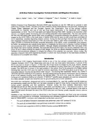
To date, the most common safing action, by far, is radiation safing. When the radiation detector senses<br />
unacceptable rates or when a decision to safe the SIs is made on the ground, the loads are stopped and the<br />
SIs stowed. This also stops the panned attitude profile. At the levels protected against by the radiation<br />
detector, radiation only poses a threat to the SIs. The vehicle could continue maneuvering without concern.<br />
Continuing the planned attitude profile would avoid the negative consequences of remaining at an<br />
unplanned attitude. It would allow for more rapid resumption of science by eliminating the need to<br />
maneuver from the attitude of the stopped observation to the first target in the resumption plan. To allow<br />
maneuvers to continue without science commanding, engineering and science loads must be separated, but<br />
run concurrently. When a safety issue threatens the SIs, but not the rest of the vehicle, only the science<br />
loads can be stopped. If a safety issue threatens both, then both sets can be stopped. In anticipation of the<br />
next solar maximum, the <strong>Chandra</strong> FOT is investigating changing the ground and flight software to allow<br />
this separation.<br />
3.3. Anomaly Response<br />
To date, the anomalies on <strong>Chandra</strong> have been detected well before they caused a safing monitor limit to be<br />
reached. Several anomalies have, however, required changes to mission schedules. If the running loads<br />
must be reworked to mitigate or work around an anomaly, the TOO scheduling process, without the effort<br />
of generating an OR for a new observation, is used to re-plan observations and engineering activities. If the<br />
loads cannot be reworked in-time to avoid undesirable reconfigurations, then they will be stopped and the<br />
SIs stowed. In this case, the safing response re-plan process is followed.<br />
When an anomaly requires a long term change to the scheduling process, the MPCWG coordinates the<br />
required changes. New constraints often start out very conservative. The conservatism combined with the<br />
learning curve for schedulers working with a new rule and the lack of automated tools to help adhere to the<br />
new constraint can cause a temporary decline in scheduling efficiency and increase in scheduling effort.<br />
The MPCWG works to mitigate the decline, by investigating safe ways to relax the new constraint and<br />
methods to help the planners work within it.<br />
4. Conclusions<br />
The mission scheduling process requires balancing many factors, such as, observation constraints, observer<br />
preferences, maneuver size, momentum accumulation and unloading, mechanism motions, thermal<br />
management and attitude restrictions. Such a complex problem leads people to want to develop an<br />
algorithm that does all of the work, a “black box” scheduling system that ingests requests and outputs a<br />
schedule with no manual intervention. However, such a system simply cannot support rapid changes to<br />
constraints and priorities and cannot answer questions when problems arise. Maintaining mission<br />
scheduling capability in the face of evolving constraints and expectations requires a method that allows<br />
specifying how requests are scheduled. To prevent such specifications from being trail and error, the<br />
system must provide the user with the information required to make scheduling decisions. The <strong>Chandra</strong><br />
Mission Planners use visual representations of the schedule and the constraints to assemble a set of<br />
maneuvers and dwells that achieves the scientific goals of the mission, without compromising vehicle<br />
safety, in the most efficient manner possible. Optimization routines can be very helpful in solving the<br />
complex problem of mission scheduling, but they cannot be the only answer. A scheduling algorithm<br />
cannot work with engineers as constraints evolve, and cannot rapidly change its priorities and rules the way<br />
the human brain can. Adaptive mission scheduling requires a balance of automated tools and human input.
Providing the scheduler with all of the information that goes into scheduling and using optimization<br />
routines to aid, not replace, the scheduler allows mission scheduling to evolve as the vehicle ages.<br />
Like any program, <strong>Chandra</strong> has experienced problems that were unanticipated before launch. To date, a<br />
majority of the problems experienced have been successfully mitigated by modifying mission scheduling.<br />
However, at one time these mitigations over-constrained the scheduling problem and caused a drastic<br />
reduction in science time efficiency. By introducing scheduling process controls and a cross-team group<br />
tasked with balancing spacecraft safety and scheduling capability the <strong>Chandra</strong> mission recovered this lost<br />
efficiency. New tools that anticipate constraint impacts allow proactive investigation and planning and<br />
have successfully kept scheduling efficiency high, despite several new constraints.<br />
The tools and techniques developed during the operational portion of the <strong>Chandra</strong> mission have allowed the<br />
mission scheduling process to adapt to new constraints and changing expectations. An environment that<br />
fosters innovation empowered the FOT to develop these new tools and processes and continues to<br />
encourage improvements to this day. Constant innovation has expanded the resources available to<br />
schedulers, keeping the scheduling process in control, despite increasing complexity.