AM Modulation and Demodulation - University of Dayton : Homepages
AM Modulation and Demodulation - University of Dayton : Homepages
AM Modulation and Demodulation - University of Dayton : Homepages

You also want an ePaper? Increase the reach of your titles
YUMPU automatically turns print PDFs into web optimized ePapers that Google loves.
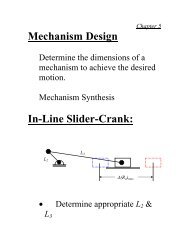
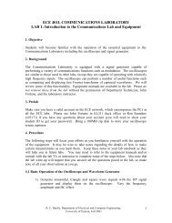
v2() t<br />
(V)<br />
0.3<br />
0.25<br />
0.2<br />
0.15<br />
0.1<br />
0.05<br />
Figure 4: Input/Output voltage relationship for nonlinear circuit (data from PSPICE with D1N4148<br />
diode <strong>and</strong> 1.8k Ohm resistor wi th no additional load).<br />
3. Prelab Assignment<br />
0<br />
0.2 0.3 0.4 0.5 0.6 0.7 0.8<br />
v1() t (V)<br />
Figure 5: Envelope detector for simple demodulation <strong>of</strong> DSB-LC signals.<br />
• Design a simple RLC b<strong>and</strong>pass filter centered at 600kHz with a 40kHz b<strong>and</strong>width (i.e.,<br />
attenuation < -3dB in a 40kHz passb<strong>and</strong>) using available component values. The lab has<br />
10uH, 47uH, <strong>and</strong> 100uH inductors. The available resistor values are shown in Table 1<br />
<strong>and</strong> the available capacitor values are shown in Table 2. Make sure you convert your<br />
design frequencies to radians/sec before using st<strong>and</strong>ard filter formulas. Verify your<br />
design with a PSPICE frequency sweep analysis.<br />
R. C. Hardie, Department <strong>of</strong> Electrical <strong>and</strong> Computer Engineering,<br />
<strong>University</strong> <strong>of</strong> <strong>Dayton</strong>, Fall 2003<br />
4