Learning Autodesk® Maya® 2008 - Digital River
Learning Autodesk® Maya® 2008 - Digital River
Learning Autodesk® Maya® 2008 - Digital River

You also want an ePaper? Increase the reach of your titles
YUMPU automatically turns print PDFs into web optimized ePapers that Google loves.
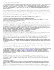
Official Autodesk Training Guide<br />
<strong>Learning</strong><br />
Autodesk ®<br />
Maya ®<br />
<strong>2008</strong><br />
The Special Effects Handbook<br />
A hands-on introduction to key tools and techniques in Autodesk Maya <strong>2008</strong><br />
based on the LAIKA short film Moongirl<br />
Free Model<br />
From Turbo Squid<br />
Value US $100.00
Table of Contents<br />
How to use this book 10<br />
Project 01<br />
Lesson 01 Materials 15<br />
Lesson 02 Textures 45<br />
Project 02<br />
Lesson 03 Lighting 77<br />
Lesson 04 Shadows 97<br />
Lesson 05 Cameras 131<br />
Lesson 06 Raytracing 151<br />
Project 03<br />
Lesson 07 Controlling Renders 163<br />
Lesson 08 Special Effects and Compositing 187<br />
Lesson 09 Hardware Rendering 209<br />
Lesson 10 Vector Rendering 219<br />
Lesson 11 Maya Paint Effects 237<br />
Project 04<br />
Lesson 12 Caustics and Global Illumination 247<br />
Lesson 13 Final Gathering and HDRI 259<br />
Lesson 14 mental ray Shaders 281
Project 05<br />
Lesson 15 Maya Dynamics 317<br />
Lesson 16 Rigid Body Dynamics 323<br />
Lesson 17 Rigid Body Constraints 337<br />
Lesson 18 Rigid Body Optimization 351<br />
Project 06<br />
Lesson 19 Introduction to Particles 371<br />
Lesson 20 Rigid Bodies and Particles 409<br />
Lesson 21 Particle Collisions 415<br />
Lesson 22 Particle Expressions 431<br />
Lesson 23 The emit Function 449<br />
Lesson 24 Advanced Particle Expressions 467<br />
Lesson 25 Goals 481<br />
Lesson 26 Particle Instancing 495<br />
Project 07<br />
Lesson 27 Rendering Particles 519<br />
Lesson 28 Compositing 545<br />
Project 08<br />
Lesson 29 Maya Fluids 557<br />
Lesson 30 Maya Fur 579<br />
Lesson 31 Maya Hair 599<br />
Lesson 32 Maya nCloth 625<br />
Index 642
•<br />
•<br />
•<br />
•<br />
Lesson 08<br />
Special Effects and Compositing<br />
Once you have modeled, textured, and added lights to your scene, there are a number of special<br />
effects you can include to enhance the quality of your render before and after rendering.<br />
In this lesson you will learn the following:<br />
How to control glow;<br />
How to use motion blur;<br />
How to use mental ray motion blur;<br />
How to use depth of field;<br />
•<br />
How to render for compositing.
Project 03<br />
188<br />
Project 03<br />
Special effects<br />
OpticalFX lets you add glows, halos, and lens flares to lights. Those effects can be used to<br />
simply brighten up a light source or to create explosions, rocket thrusters, and other special<br />
effects. Shader glow can be used to brighten up a material with a luminous radiance. It can be<br />
used to create lava, neon lights, and other glow effects.<br />
Light glow<br />
In the real world, when light shines directly into an observer’s eye or into a camera’s lens, the<br />
light source may appear to glow. If the light passes through a mesh (for example, a star filter on<br />
a camera) or through hair or eyelashes, the light will refract, producing a star-like glow. In some<br />
cases, the light may reflect off the surface of a camera’s compound lens and produce a lens<br />
flare. These are all examples of optical light effects.<br />
When lights appear to glow, it is purely a retinal effect in the eye. To see this, look up at a light<br />
source such as a street light and squint. You will see a glow around the light. Now use your<br />
finger to block only the light source; the glow disappears. Notice also that if you cover only<br />
part of the light source, the glow is still visible and will in fact appear in front of your finger.<br />
The light glow in Maya simulates this real world effect of blocking the light source, called<br />
occlusion.<br />
Light glow occlusion<br />
The most common issue that arises when working with light glow in Maya is the need to<br />
control Light Source Occlusion. Often people will animate the position of objects that pass<br />
in front of glowing lights and will find that the glow shows right through the objects. This is<br />
because the light needs you to specify how big or small the light source actually is in order to<br />
know when it is completely covered by an object.<br />
Note: The light glow feature is only supported by the Maya software renderer.<br />
1 Create a light glow<br />
•<br />
Open a point light’s Attribute Editor.<br />
• In the Light Effects section, click on the map button beside the Light Glow.<br />
An opticalFX node is automatically created, connected to the light node, and displayed in<br />
the Attribute Editor. Also, a new icon has appeared, surrounding the light source in the views.<br />
LeArNING AUtoDeSK MAYA <strong>2008</strong> | tHe SPecIAL eFFectS HANDBooK
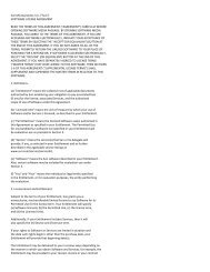
2 Set the size of the light source<br />
Now that you have created a glow effect,<br />
you need to consider how you want this<br />
glow to behave. Recall that the light glow<br />
is only going to shut off completely if the<br />
entire light source is occluded. If the light<br />
is going to pass behind an object, the size<br />
of this sphereShape icon, relative to the<br />
size of the object, will determine whether<br />
you see the glow though the object or not.<br />
•<br />
Select the light glow icon in one of the views.<br />
LeSSoN 08: SPecIAL eFFectS AND coMPoSItING<br />
Note: Adjusting the Radius attribute will not affect the appearance of the light glow. It is<br />
only used to determine occlusion.<br />
Comparison of different radius values<br />
Point light OpticalFX icon<br />
Notice that a new tab appears in the Attribute Editor, called sphereShape.<br />
• Click on the sphereShape tab.<br />
• Select Render Sphere Attributes → Radius.<br />
• Use this Radius attribute to adjust the size of the icon in the scene.<br />
In the images shown above, a glowing point light moves from left to right behind the columns.<br />
In the middle images, the glow is partially dimmed with a radius of 1.0, increasingly dimmed<br />
with a radius of 0.3, and fully occluded with a radius of 0.1.<br />
LeArNING AUtoDeSK MAYA <strong>2008</strong> | tHe SPecIAL eFFectS HANDBooK<br />
Lesson 08: Special Effects and Compositing 189
Project 03<br />
190<br />
Project 03<br />
Shader glow<br />
Unlike light glow, shader glow in a scene is controlled by a single shaderGlow node. This node<br />
can be found in the Hypershade window, under the Materials tab.<br />
1 Scene file<br />
• Open the scene file called 08-glow_01.ma.<br />
This scene contains a big star fish with pre-created shading network and a<br />
textured background.<br />
2 Add a glow effect to the fish<br />
•<br />
Select the fish geometry.<br />
• In the Hypershade, click the Graph materials on selected objects button.<br />
The fish already has a shading network that mimics stars on its skin.<br />
• Select the fish:lambert2 material.<br />
• In the Attribute Editor, scroll to the Special Effects section and set<br />
Glow Intensitiy to 1.0.<br />
• Render the scene.<br />
You should see a glow where the material is not black. The glow is bluish because it inherits<br />
of the color of the stars. Also, the stars are connected to the incandescence of the material,<br />
so they will be visible even if there are no lights in the scene.<br />
The star material with glow<br />
LeArNING AUtoDeSK MAYA <strong>2008</strong> | tHe SPecIAL eFFectS HANDBooK
3 Hide the source object<br />
• Open the Special Effects section and set Hide Source to On.<br />
•<br />
LeSSoN 08: SPecIAL eFFectS AND coMPoSItING<br />
The Hide Source attribute will render the glow without the geometry, giving an<br />
interesting effect.<br />
Render the scene.<br />
4 Shader glow<br />
The hide source effect<br />
By modifying a scene’s shader glow, you will affect how the glow renders for your entire<br />
scene. You can achieve some very interesting effects by tweaking this specialized shader.<br />
• In the Hypershade, select the Materials tab.<br />
• Open the Attribute Editor for the shaderGlow1 node.<br />
Try to change the<br />
• Glow Type and Halo Type to different values, and then<br />
render your scene.<br />
LeArNING AUtoDeSK MAYA <strong>2008</strong> | tHe SPecIAL eFFectS HANDBooK<br />
Lesson 08: Special Effects and Compositing 191
Project 03<br />
192<br />
Project 03<br />
Creating a neon effect<br />
Neon tubes are the quintessential shader glow example. Try this to create a realistic<br />
neon effect.<br />
1 Create the shader<br />
• Create a Surface Shader material and assign it to any object.<br />
• Set the Out Color attribute to a bright color.<br />
• Set the Out Glow Color to a darker complementary color.<br />
Notice how you are able to set the glow color directly.<br />
2 Render the effect<br />
Modified shader glow<br />
Surface shader glow<br />
LeArNING AUtoDeSK MAYA <strong>2008</strong> | tHe SPecIAL eFFectS HANDBooK
LeSSoN 08: SPecIAL eFFectS AND coMPoSItING<br />
With other material types, there is no attribute to control the shader glow color directly. It is<br />
derived from the glow color on the shaderGlow node and the color of the material. With the<br />
surface shader material, it is possible to experiment with different combinations of glow color<br />
and surface color. Also, because the surface shader has no sense of a shading model, it renders<br />
as though it is self illuminating—perfect for neon tubes, L.E.D. displays, etc.<br />
Motion blur<br />
Motion blur simulates how a real camera works if objects are moving while the camera’s<br />
shutter is still open. This technique is very common in the entertainment industry for creating<br />
photorealistic images and animation involving quick motions.<br />
With the Maya software renderer, there are two types of motion blur: 2D and 3D. The shutter<br />
angle determines the blur length, but this can be overridden in the Render Settings. This<br />
matter will be discussed later in the lesson.<br />
Understand the shutter angle<br />
Whether using 2D or 3D motion blur, it is important to understand the shutter angle.<br />
The motion blur algorithm uses a shutter open, shutter mid and shutter close sample for<br />
every frame to determine the change in position of a given triangle.<br />
Note: Triangle refers to a tessellation triangle on a surface.<br />
The shutter angle that you specify for motion blur will determine the resulting amount of<br />
blur to be calculated. Following is how the motion blur is calculated, taking into account the<br />
shutter angle:<br />
Take the Shutter Angle value (the default is 144), and divide it by 360-degrees.<br />
For example, 144 / 360 = 0.4.<br />
0.4 represents the interval in time between the shutter open and shutter close samples.<br />
Shutter mid is always the frame time itself. For example, for motion blur at frame 1, shutter<br />
open would be at frame 0.8 and shutter closed would be at frame 1.2. However, when we<br />
calculate motion blur for mental ray, we calculate forward only.<br />
By this, you can see that a shutter angle of 360-degrees would give shutter open and close<br />
samples that are exactly one frame apart, i.e. 360/360= 1.<br />
You will notice that by setting the shutter angle to 360, we increased the amount of motion<br />
blur. This is because the longer the shutter is open (i.e. the further apart the shutter open and<br />
shutter close samples are taken), the blurrier a moving object will appear to be.<br />
LeArNING AUtoDeSK MAYA <strong>2008</strong> | tHe SPecIAL eFFectS HANDBooK<br />
Lesson 08: Special Effects and Compositing 193
Project 03<br />
194<br />
Project 03<br />
How to change the shutter angle<br />
•<br />
Open the Attribute Editor for the camera.<br />
• Open the Special Effects section.<br />
• Adjust the Shutter Angle attribute.<br />
mental ray motion blur<br />
In mental ray, there are two types of motion blur: Linear (transformation) and Exact<br />
(deformation). Motion blur in mental ray<br />
blurs everything: shaders, textures, lights,<br />
shadows, reflections, refractions, and<br />
caustics. The shutter angle determines the<br />
blur path length, but this can be adjusted by<br />
the mental ray motion blur attributes in the<br />
Render Settings.<br />
To turn On motion blur in mental ray, go to<br />
the mental ray Render Settings and open up<br />
the Motion Blur section. From there, you can<br />
select one of the options from the calculation<br />
drop-down menu.<br />
Note: Motion blur in mental ray is calculated forward only.<br />
Linear vs. exact motion blur<br />
LeArNING AUtoDeSK MAYA <strong>2008</strong> | tHe SPecIAL eFFectS HANDBooK<br />
Blurred shadows and<br />
reflections using mental ray<br />
As it is with the software renderer’s motion blur, the decision whether to use linear (2D) or<br />
exact (3D) mental ray motion blur depends on the type of motion of your object, as well as<br />
the time available to render the animation. Linear motion blur is faster to calculate than exact<br />
motion blur.<br />
Linear motion blur only takes into account an object’s transformation, rotation, and scale.<br />
The object’s deformation will not be considered. For example, if you have blend shapes or a<br />
skeleton that deforms a piece of geometry, the resulting motion wouldn’t be considered when<br />
calculating this type of motion blur.<br />
Exact takes into account all the transformations as well as the object’s deformations. This type<br />
of blur is more expensive to render.<br />
Note: An object’s motion blur can be turned off in its Render Stats section of the<br />
Attribute Editor.
Editing mental ray motion blur<br />
LeSSoN 08: SPecIAL eFFectS AND coMPoSItING<br />
Motion Blur By is a multiplier for the Shutter Angle. The larger this value, the longer the<br />
shutter remains open, resulting in more blur.<br />
Shutter represents the length of time the camera’s shutter is open. The longer a shutter is<br />
open, the more blurry an object will be. However, unlike a real camera, the shutter value does<br />
not affect the brightness of an image. If the shutter is set to 0, there will be no motion blur.<br />
Larger values increase the length of the blur.<br />
Shutter Delay represents the normalized time that a shutter remains closed before opening.<br />
For instance, if the shutter delay is set to 0, the shutter opens at the beginning of the frame. If<br />
the shutter delay is set to .5, it opens halfway through the frame.<br />
There are four separate controls for Time Contrast: Red, Green, Blue and Alpha. If you have<br />
a fast-moving object, these values can usually be set high. Motion blur tends to make sampling<br />
artifacts less noticeable, so you can get away with higher contrast values (in other words,<br />
lower quality settings). However, if you find that your motion blur is grainy, you can smooth it<br />
by decreasing your time contrast values. The lower the time contrast values, the greater your<br />
render times.<br />
Tip: Always try fixing the quality of motion blur by decreasing Time Contrast values first<br />
and Number of Samples last. This way, you can increase render performance while<br />
not compromising non-blurred anti-aliasing.<br />
Motion Steps can create motion paths from motion transforms. The image on the left<br />
represents a value of 1 for motion steps. The image on the right represents a value of 8 for<br />
motion steps. Notice the rounder blur on the outer edges of the blade on the right.<br />
Different amount of motion steps<br />
LeArNING AUtoDeSK MAYA <strong>2008</strong> | tHe SPecIAL eFFectS HANDBooK<br />
Lesson 08: Special Effects and Compositing 195
Project 03<br />
196<br />
Project 03<br />
2D vs. 3D motion blur<br />
The decision whether to use 3D or 2D motion blur is really a matter of determining which one is<br />
more appropriate for a given scene and the time available to render the animation. 3D motion<br />
blur is usually slower and more memory intensive. However, there will be times when 3D<br />
motion blur is required because of some limitations of 2D blur (discussed in the next section).<br />
In general, it is recommended that you try to use 2D motion blur because it is very fast and<br />
produces excellent results in most cases. All of the motion blur attributes, other than Shutter<br />
Angle, are found in the Render Settings under the Motion Blur section. If it is desirable for<br />
motion blur to be off for some objects, open the Attribute Editor for those objects and toggle<br />
Off the motion blur in the Render Stats section.<br />
The following example compares the results of 2D vs. 3D motion blur.<br />
Limitations of 2D motion blur<br />
Comparison between 2D (left) and 3D (right) motion blur<br />
There was quite a difference in rendering time for the above images. The 3D motion blur image<br />
took about four times as long as the 2D motion blur image to render.<br />
Note: Motion vector files can be used by other programs to generate blur.<br />
2D motion blur does not work well in these situations:<br />
Moving transparent objects with a background<br />
The background will also be blurred in this case. The solution is to blur the transparent object<br />
separately and composite it into the rest of the scene.<br />
LeArNING AUtoDeSK MAYA <strong>2008</strong> | tHe SPecIAL eFFectS HANDBooK
Detailed background behind moving objects<br />
LeSSoN 08: SPecIAL eFFectS AND coMPoSItING<br />
Some details might be lost since the renderer has to make assumptions about the background<br />
area occluded by the moving objects. The solution is to blur the moving objects without the<br />
background and then composite the results.<br />
Fast rotating objects<br />
A motion vector can be thought of as the direction of a pixel in 3D. This vector does not<br />
contain any rotation values, so the rendered image will show a linear movement because it<br />
does not know about the arc motion of the pixel in between the first and last positions.<br />
Objects entering from outside the image or leaving the image<br />
The renderer does not know the object color outside of the image and has to make<br />
assumptions. The solution is to render a slightly larger image, which covers the original image,<br />
and then crop it to the desired size.<br />
Volume objects (particles, fog) and image planes<br />
Motion vectors are only calculated for moving triangles (tessellated NURBS and poly meshes).<br />
Note: The rendered results from 3D and 2D are quite different. It is not a good idea to mix<br />
the rendered images from these two kinds of blurring operations.<br />
Depth of field<br />
Depth of field is a photographic effect in which objects within a certain range of distance<br />
remain sharply focused. Objects outside this range appear out of focus. You can simulate this<br />
using the camera’s Depth of Field attribute. This is not a post-process effect in mental ray, but<br />
true depth of field.<br />
1 Setting up the camera for depth of field<br />
• Open the file 08-depthOfField_01.ma.<br />
• In a four-view layout, set camera1 to replace the Perspective view.<br />
• In the top view, select camera1 and press t to show the camera’s Manipulators. Place<br />
the Center of Interest at the location you want to remain in focus.<br />
• Select Window → General Editors → Connection Editor.<br />
• Open the Hypershade and select the camera you are using from the Cameras tab.<br />
• Reload this camera into both sides of the Connection Editor.<br />
• Connect the Center of Interest to the Focus Distance.<br />
LeArNING AUtoDeSK MAYA <strong>2008</strong> | tHe SPecIAL eFFectS HANDBooK<br />
Lesson 08: Special Effects and Compositing 197
Project 03<br />
198<br />
Project 03<br />
Note: Another alternate but equally useful workflow in setting up depth of field is to<br />
use the Distance Tool. This can be found under Create → Measure Tools →<br />
Distance Tool. This will allow you to measure the distance between the camera and<br />
the point in your scene that you want to use as the focus distance.<br />
2 Enable depth of field<br />
• In the Attribute Editor for the camera, open the Depth of Field section.<br />
• Set the Depth of Field flag to On.<br />
• Adjust the F Stop to control the amount of depth of field.<br />
The F Stop value represents the distance in front of and behind the focus distance that will<br />
remain in focus. A low value represents a short distance that will be in focus; a very high<br />
value F-stop will result in very little blur because a deeper range is in focus. In essence, the<br />
lower the F-stop value, the smaller the region in focus will be.<br />
Image rendered with depth of field<br />
Tip: It is possible to use Render Region to test render depth of field.<br />
LeArNING AUtoDeSK MAYA <strong>2008</strong> | tHe SPecIAL eFFectS HANDBooK
Limitations of depth of field<br />
LeSSoN 08: SPecIAL eFFectS AND coMPoSItING<br />
Transparent surfaces can cause problems with depth of field. The technical reason for<br />
this limitation is that the transparent surface is at a certain depth from the camera. The<br />
renderer only stores one depth per pixel, and it chooses to store the nearest point to the<br />
eye. For transparent surfaces, the depth of the transparent surface will determine the blur,<br />
so the background will show through, un-blurred. The background, when seen through the<br />
transparent object, will be blurred at the same depth as the transparent surface. This limitation<br />
is not limited to Maya and has led to the industry accepted practice of rendering components<br />
separately and compositing them.<br />
Reasons to render for compositing<br />
Compositing is the process of merging multiple layers of image information into one image<br />
to create a final look. A common misconception is that compositing is for large productions<br />
with many artists. However, smaller production facilities and individual artists can also benefit<br />
from the opportunities and advantages offered by compositing. For example, with compositing<br />
you can:<br />
• Have the flexibility to re-render or color-correct individual elements without having to<br />
re-render the whole scene.<br />
• Increase creative potential and achieve effects with the 2D compositing package that<br />
are not possible with the renderer.<br />
• Take advantage of effects that are faster and more flexible in 2D, such as depth of field<br />
and glow, rather than rendering them in 3D.<br />
• Combine different looks from different renderers, such as hardware and software<br />
particle effects.<br />
•<br />
Combine 3D rendered elements with 2D live action footage.<br />
• Save time when rendering scenes where the camera does not move; you only need to<br />
render one frame of the background to be used behind the whole animation sequence.<br />
• Successfully render large complex scenes in layers so that you don’t exceed your<br />
hardware and software memory capabilities.<br />
Set up a render for compositing<br />
Rendering in layers refers to the process of separating scene elements so that different objects<br />
or sets of objects can be rendered as separate images. The first step is to determine how to<br />
divide the scene into layers. This may be very simple or incredibly complex and will depend<br />
entirely on your needs for any given project. Once you have decided how you want to separate<br />
your scene elements, there are several workflow approaches you can use to render them<br />
separately.<br />
LeArNING AUtoDeSK MAYA <strong>2008</strong> | tHe SPecIAL eFFectS HANDBooK<br />
Lesson 08: Special Effects and Compositing 199
Project 03<br />
200<br />
Project 03<br />
Rendering with render layers<br />
A typical approach to separating your scene elements is to use Render Layers. You can assign<br />
objects to render layers using the same workflow as you would when working with display<br />
layers.<br />
Render layers allow you to organize the objects in your scene specifically to meet your<br />
rendering needs. The most basic approach might be to separate objects into foreground,<br />
midground and background layers. Or, you may decide to divide the scene elements by specific<br />
objects or sets of objects.<br />
Compositing<br />
flag to be used<br />
Layers to<br />
be rendered<br />
Render options<br />
of layers<br />
Render Layer Editor<br />
If you need very precise control over the color of your rendered objects, separate from the<br />
shadows on them, you can further break down your shot by rendering separate passes within<br />
any render layer. The term render passes generally refers to the process of rendering various<br />
attributes separately such as color, shadows, specular highlights, etc. The Render Layers Editor<br />
allows you to set this up.<br />
The following images show Leon rendered with different render passes: specular highlights<br />
(left) and diffuse (center). The last image on the right shows the resulting composited image.<br />
LeArNING AUtoDeSK MAYA <strong>2008</strong> | tHe SPecIAL eFFectS HANDBooK<br />
Display /<br />
Render layers<br />
Create new layers<br />
Only the active<br />
layer is displayed<br />
Display all<br />
objects<br />
Specular and color rendered as separate render passes and composited
LeSSoN 08: SPecIAL eFFectS AND coMPoSItING<br />
Tip: Render passes are not limited to the example above. You can easily render beauty,<br />
shadow, specular, color and diffuse passes by setting simple checkboxes to On.<br />
The alpha channel<br />
When rendering objects for compositing, one of the most important requirements is an alpha<br />
channel. The alpha channel, sometimes called a mask or matte, contains information about the<br />
coverage and opacity of objects in an image. This information is later used by the compositing<br />
application to combine the images.<br />
In the alpha channel, opaque regions of objects are white, and fully transparent objects or<br />
empty spaces are black. The grayscale regions in the alpha channel mean semi-transparent<br />
objects.<br />
The following image shows the alpha channel for Leon and the boat.<br />
Matte opacity<br />
Alpha and RGB channels<br />
There are many cases where compositing the separate elements of even a simple scene can be<br />
tricky and require careful planning.<br />
The following image depicts the compositing of two separately rendered objects. A problem<br />
exists where, for example, Leon stands in the boat, and his geometry is both in front of and<br />
behind some of the boat’s geometry. This is because the alpha channel does not contain any<br />
information about what part of an object goes in front or behind other objects. For this reason,<br />
the compositing application doesn’t know this information either.<br />
LeArNING AUtoDeSK MAYA <strong>2008</strong> | tHe SPecIAL eFFectS HANDBooK<br />
Lesson 08: Special Effects and Compositing 201
Project 03<br />
202<br />
Project 03<br />
The Matte Opacity feature provides one way to resolve this dilemma.<br />
Leon in front of the boat layer Leon behind the boat layer<br />
Separately rendered objects that will be difficult to composite correctly<br />
Note: In some cases, it is also possible to affect the alpha channels later, in the compositing<br />
application, to allow images to composite correctly. A third possible approach is<br />
to render the images with a depth channel for use in compositing packages with<br />
depth compositing capabilities. However, there are limitations to depth compositing<br />
techniques, so it is a good idea to learn these other methods as well.<br />
To ensure that the objects composite properly, you can use an attribute called Matte Opacity,<br />
found in the Attribute Editor for all materials. This allows you to manipulate the rendered alpha<br />
value on a per-material basis.<br />
Matte opacity found in any material’s Attribute Editor<br />
LeArNING AUtoDeSK MAYA <strong>2008</strong> | tHe SPecIAL eFFectS HANDBooK
The Matte Opacity feature has three modes:<br />
Black Hole<br />
LeSSoN 08: SPecIAL eFFectS AND coMPoSItING<br />
To solve this particular compositing problem, the Black Hole mode is useful. This mode will<br />
set the RGBA values to exactly (0,0,0,0), resulting in images with cutout regions that allow<br />
the objects to fit together correctly. The image below shows the alpha of Leon once the boat<br />
materials have been set to Black Hole.<br />
Opacity Gain<br />
Black hole used to hide parts of the objects<br />
This is the default mode for Matte Opacity. Alpha values are calculated in the normal way,<br />
and then multiplied by the Matte Opacity value. Because the Matte Opacity attribute has a<br />
default value of 1.0, the rendered alpha values remain unchanged (1.0 * x = x). However, you<br />
can adjust the matte opacity value to achieve the following effects:<br />
• Animate the matte opacity value from 0-1 or vice versa to create fade-in or fade-out<br />
effects when composited.<br />
• Texture map the matte opacity attribute to create interesting compositing effects,<br />
especially if you use an animated texture or sequence of images.<br />
LeArNING AUtoDeSK MAYA <strong>2008</strong> | tHe SPecIAL eFFectS HANDBooK<br />
Lesson 08: Special Effects and Compositing 203
Project 03<br />
204<br />
Project 03<br />
Solid Matte<br />
When Matte Opacity is in Solid Matte mode, the normally calculated alpha values are<br />
ignored in favor of the matte opacity setting. The entire matte for the object is set to the<br />
value of the matte opacity attribute. This can be useful if you need an object to have a specific<br />
alpha value. For example, if you have a transparent object, the normal alpha value calculated<br />
by the renderer will be 0. Solid matte can be used to set a non-zero value for the alpha on the<br />
transparent object. If you were rendering a view through a window and wanted to composite<br />
that into another scene, setting the matte opacity value to 1.0 (in solid matte mode) on the<br />
window’s material would help you achieve this.<br />
Note: Opacity gain and solid matte modes will not change the RGB component of your<br />
image. They will only change the alpha value generated by the shader.<br />
Altering the mattes in a compositing application<br />
Depending on what effects will be used at the compositing stage, it is sometimes important<br />
to render the whole object rather than having parts cut away with black hole. This gives you<br />
greater flexibility for effects such as blur, or overcoming moiré patterns on edges. Under<br />
these circumstances, you would need to use techniques in the compositing application in<br />
order to composite the elements correctly. This can involve manipulating a combination of<br />
the alpha values themselves, or creating custom masks to reveal/conceal objects as they are<br />
layered together.<br />
The final composite image<br />
LeArNING AUtoDeSK MAYA <strong>2008</strong> | tHe SPecIAL eFFectS HANDBooK
mental ray blurred reflections and refractions<br />
LeSSoN 08: SPecIAL eFFectS AND coMPoSItING<br />
Typically, raytraced reflections and refractions exhibit very sharp definition. In reality, there are<br />
always inaccuracies in surface finishes and impurities in material structures that cause light<br />
rays to be reflected and refracted slightly off the original ray direction.<br />
mental ray reflection and refraction blur of a material<br />
You can adjust mental ray reflection and refraction blur in the mental ray section of the<br />
material node.<br />
Reflection and refraction blur<br />
These attributes determine the amount of reflection and refraction blur. A good starting point<br />
is between 0.1 and 0.3.<br />
Reflection and refraction rays<br />
When reflection and refraction blur have been enabled, ray direction is not exactly determined<br />
by the raytracing algorithm. Reflection and refraction rays will randomly deviate as specified<br />
by the blur attributes. This attribute is used to control the amount of supersampling required<br />
by the random deviation of the ray direction. Generally, higher reflection and refraction rays<br />
are required with more blur.<br />
Use Background Shader<br />
You can also use the Use Background Shader to make 3D geometry look like it is part of a<br />
real image. For example, if you want to place Leon over a background shot of a desert, you will<br />
need his shadows to be on the sand. Doing so would greatly help to enhance the integration of<br />
CG elements into the background image.<br />
1 Scene file<br />
•<br />
Open the file called 08-waterfall_01.ma.<br />
LeArNING AUtoDeSK MAYA <strong>2008</strong> | tHe SPecIAL eFFectS HANDBooK<br />
Lesson 08: Special Effects and Compositing 205
Project 03<br />
206<br />
Project 03<br />
2 Image plane<br />
• Create an Image Plane for the camera1.<br />
• Browse for the image called waterfall.tif from the sourceimages directory.<br />
3 Environment<br />
•<br />
•<br />
Hide the set.<br />
Model a stand-in geometry that represents the content of the image plane.<br />
If you model a geometry similar to the content of the reference image, your shadows and<br />
reflections will perfectly match upon compositing.<br />
• Assign a Use Background Shader to the stand-in geometry.<br />
4 Lights<br />
•<br />
This will make the geometry disappear seamlessly into the background image, but it will<br />
catch shadows and reflections.<br />
Create lighting similar to the one in the reference image.<br />
• Turn On shadows on the lights.<br />
•<br />
Render the scene.<br />
The stand-in geometry will receive shadows, creating the illusion that Leon is actually part of<br />
the image.<br />
Stand-in geometry receives shadows and reflections<br />
LeArNING AUtoDeSK MAYA <strong>2008</strong> | tHe SPecIAL eFFectS HANDBooK
LeSSoN 08: SPecIAL eFFectS AND coMPoSItING<br />
Tip: The same approach can be used to make a 2D image on an image plane look like<br />
it is part of a 3D scene. Use the same technique for modeling stand-in geometry:<br />
Assign a Use Background Shader to the stand-ins. With the stand-in geometry<br />
casting shadows and raytraced reflections of other geometry in the 3D scene, it<br />
is very convincing.<br />
Camera projection<br />
The Use Background technique described above reaches its limit in a case where, for example,<br />
you decide you want to be able to animate something that is getting its color from part of a<br />
2D image plane. This might be a case of making a dog talk or a cat’s eyes bulge open, where<br />
the dog and cat exist in a live shot behind stand-in geometry. In this case, you can use the As<br />
Projection method of texture mapping to project the 2D image onto the stand-in, making sure<br />
that the Projection Type on the projection node is set to perspective and the Link to Camera<br />
attribute is set to the appropriate camera. Then you would do a Convert Solid Texture to<br />
create parametric texture maps on the surfaces. Once this is done, you can animate the standin<br />
geometry and render it so that it can be composited with the original images.<br />
Composite rendering<br />
If you find yourself in a situation where you are rendering an object over a background that<br />
is any color other than completely black (0, 0, 0), you should set Premultiply to Off in the<br />
Render Settings under the Render Options section.<br />
What this feature does is prevent the edges of geometry from being anti-aliased against the<br />
background color. For this reason, the RGB component of the image will look badly aliased.<br />
However, the mask channel is perfectly anti-aliased. The mask channel is what is used to<br />
blend the rendered element into the background of choice at the compositing stage.<br />
Because the composite rendering flag prevented the edges from including any of the rendering<br />
background color, you will not get an unsightly rim showing in the rendering background color<br />
after compositing.<br />
Premultiply Threshold is mainly a games feature. This is a normalized [0, 1] alpha threshold;<br />
the foreground is registered only if the alpha value is above the composite threshold.<br />
Conclusion<br />
Adding effects enhances a scene’s quality and produces some interesting results.<br />
Compositing involves rendering a scene in separate components and then merging<br />
those components together.<br />
In the next lesson, you will review hardware rendering.<br />
LeArNING AUtoDeSK MAYA <strong>2008</strong> | tHe SPecIAL eFFectS HANDBooK<br />
Lesson 08: Special Effects and Compositing 207