SIP Trunking Configuration Guide for Adtran NetVanta 7100 Office In ...
SIP Trunking Configuration Guide for Adtran NetVanta 7100 Office In ...
SIP Trunking Configuration Guide for Adtran NetVanta 7100 Office In ...

You also want an ePaper? Increase the reach of your titles
YUMPU automatically turns print PDFs into web optimized ePapers that Google loves.
www.CoxBusiness.com<br />
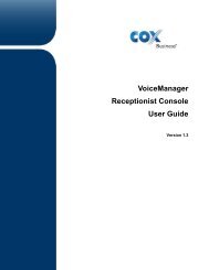
<strong>SIP</strong> <strong>Trunking</strong> <strong>Configuration</strong> <strong>Guide</strong><br />
<strong>for</strong><br />
<strong>Adtran</strong> <strong>NetVanta</strong> <strong>7100</strong> <strong>Office</strong> <strong>In</strong> A Box<br />
A4.03.00.SC.E<br />
© 2012, Cox Communications, <strong>In</strong>c. All rights reserved.<br />
This documentation is the confidential and proprietary intellectual property of Cox<br />
Communications, <strong>In</strong>c. Any unauthorized use, reproduction, preparation of derivative works,<br />
per<strong>for</strong>mance, or display of this document, or software represented by this document is strictly<br />
prohibited.
Table of Contents<br />
1 Audience ................................................................................................................................................ 4<br />
2 <strong>In</strong>troduction ............................................................................................................................................ 4<br />
2.1 tekVizion Labs ................................................................................................................................ 5<br />
3 <strong>SIP</strong> <strong>Trunking</strong> Network Components ...................................................................................................... 6<br />
3.1 Hardware Components ................................................................................................................... 7<br />
3.2 Software Requirements .................................................................................................................. 7<br />
4 Features ................................................................................................................................................. 8<br />
4.1 <strong>SIP</strong> Registration Method ................................................................................................................. 8<br />
4.2 Features Supported ........................................................................................................................ 8<br />
4.3 Features Not Supported ................................................................................................................. 8<br />
5 Caveats and Limitations......................................................................................................................... 9<br />
6 <strong>Configuration</strong> ........................................................................................................................................ 10<br />
6.1 <strong>Configuration</strong> Checklist ................................................................................................................. 10<br />
6.2 IP Address Worksheet .................................................................................................................. 11<br />
6.3 <strong>NetVanta</strong> <strong>7100</strong> Detailed <strong>Configuration</strong> Steps............................................................................... 12<br />
6.3.1 Set System IP Address ......................................................................................................... 12<br />
6.3.2 VLAN <strong>Configuration</strong> ............................................................................................................... 17<br />
6.3.3 DHCP Server ......................................................................................................................... 20<br />
6.3.4 Set System Parameters ........................................................................................................ 22<br />
6.3.5 Configure Eth 0/1 .................................................................................................................. 23<br />
6.3.6 Create Trunk .......................................................................................................................... 25<br />
6.3.7 Trunk Groups ......................................................................................................................... 30<br />
Table of Figures<br />
Figure 1 – Cox Fiber Network ....................................................................................................................... 4<br />
Figure 2 – <strong>SIP</strong> Trunk Lab Reference Network .............................................................................................. 6<br />
Figure 3 – Set IP Address in PC ................................................................................................................. 12<br />
Figure 4 – <strong>Adtran</strong> <strong>NetVanta</strong> Back view ....................................................................................................... 13<br />
Figure 5 – Enter Username and Password ................................................................................................. 13<br />
Figure 6 – Physical <strong>In</strong>terfaces ..................................................................................................................... 14<br />
Figure 7 – Eth 0/0 ........................................................................................................................................ 15<br />
Figure 8 – Add Static Route ........................................................................................................................ 16<br />
Figure 9 – Save and Reboot ....................................................................................................................... 17<br />
Figure 10 – Default VLANs ......................................................................................................................... 17<br />
Figure 11 – Default VLAN ........................................................................................................................... 18<br />
Figure 12 – VoIP VLAN ............................................................................................................................... 19<br />
Figure 13 – DHCP Server Settings ............................................................................................................. 20<br />
Figure 14 – DHCP Excluded Ranges ......................................................................................................... 21<br />
Figure 15 – System Parameters ................................................................................................................. 22<br />
Figure 16 – System Parameters continued ................................................................................................. 23<br />
Figure 17 – Physical <strong>In</strong>terface 0/1 .............................................................................................................. 23<br />
Figure 18 – eth 0/1 <strong>Configuration</strong> ............................................................................................................... 24<br />
Figure 19 – Allowed VLAN List ................................................................................................................... 25<br />
Figure 20 – Create Trunk Account .............................................................................................................. 25<br />
Figure 21 – Modify <strong>SIP</strong> Trunk ..................................................................................................................... 26<br />
Figure 22 – Modify <strong>SIP</strong> Trunk cont ............................................................................................................. 27<br />
Figure 23 – Modify <strong>SIP</strong> Trunk cont ............................................................................................................. 28<br />
Property of Cox Communications, <strong>In</strong>c. Version 1.0<br />
Page 2 of 31
Figure 24 – Add Register Entry ................................................................................................................... 29<br />
Figure 25 – Add TrunkGroup ...................................................................................................................... 30<br />
Figure 26 – Default Outbound Call Templates <strong>for</strong> Trunk Group ................................................................. 31<br />
Table of Tables<br />
Table 1 – PBX <strong>Configuration</strong> Steps ............................................................................................................ 10<br />
Table 2 – IP Addresses ............................................................................................................................... 11<br />
Property of Cox Communications, <strong>In</strong>c. Version 1.0<br />
Page 3 of 31
1 Audience<br />
This document is intended <strong>for</strong> the <strong>SIP</strong> trunk customer’s technical staff and Value Added Retailer (VAR)<br />
having installation and operational responsibilities.<br />
2 <strong>In</strong>troduction<br />
This <strong>Configuration</strong> <strong>Guide</strong> describes configuration steps <strong>for</strong> Cox <strong>SIP</strong> trunking to a <strong>NetVanta</strong> <strong>7100</strong> “<strong>Office</strong> <strong>In</strong><br />
A Box” IP-PBX. Cox <strong>SIP</strong> trunking is a scalable and efficient IP trunking telecommunication solution <strong>for</strong><br />
your business that provides all the traditional services such as Direct <strong>In</strong>ward Dialing, Hunting, Calling<br />
Name, Calling Number, Local/Long Distance and Business Continuity options, including:<br />
Burstable Trunk Capacity – Dynamically increases call capacity during peak busy periods so your<br />
customers never receive a busy signal.<br />
Call Forward Always – On the trunk group pilot number <strong>for</strong> all calls in case of an outage (i.e.,<br />
flood, fire, loss of power, etc.).<br />
Call Forward Not Reachable – On the trunk group pilot number that operates on a per-call<br />
contingency basis to <strong>for</strong>ward the call to any PSTN number (i.e., call center or alternate office<br />
location) during temporary call completion impairments.<br />
Route Exhaustion – Automatic reroute of trunk group calls to any PSTN phone number (i.e., a call<br />
center) if calls can’t be completed to the PBX.<br />
Support <strong>for</strong> geo-redundant PBX deployments and automatic reroute of <strong>SIP</strong> trunks to the backup<br />
customer data center.<br />
All calls are routed over Cox’s national fiber network with guaranteed Quality of Service (QoS); calls never<br />
traverse the <strong>In</strong>ternet.<br />
Figure 1 – Cox Fiber Network<br />
Property of Cox Communications, <strong>In</strong>c. Version 1.0<br />
Page 4 of 31
2.1 tekVizion Labs<br />
tekVizion Labs TM is an independent testing and Verification facility offered by tekVizion PVS, <strong>In</strong>c.<br />
(“tekVizion”). tekVizion Labs offers several types of testing services including:<br />
Remote Testing – provides secure, remote access to certain products in tekVizion Labs <strong>for</strong><br />
pre-Verification and ad hoc testing<br />
Verification Testing – Verification of interoperability per<strong>for</strong>med on-site at tekVizion Labs<br />
between two products or in a multi-vendor configuration (“solution Verification”)<br />
Product Assessment – independent assessment and verification of product functionality,<br />
interface usability, assessment of differentiating features as well as suggestions <strong>for</strong> added<br />
functionality, stress and per<strong>for</strong>mance testing, etc.<br />
tekVizion is a systems integrator specifically dedicated to the telecommunications industry. Our core<br />
services include consulting/solution design, interoperability/Verification testing, integration, custom<br />
software development and solution support services. Our services helps service providers achieve a<br />
smooth transition to packet-voice networks, speeding delivery of integrated services. While we have<br />
expertise covering a wide range of technologies, we have extensive experience surrounding our<br />
FastForward>> practice areas which include: <strong>SIP</strong> <strong>Trunking</strong>, Packet Voice, Service Delivery, and<br />
<strong>In</strong>tegrated Services.<br />
The tekVizion team brings together experience from the leading service providers and vendors in<br />
telecom. Our unique expertise includes legacy switching services and plat<strong>for</strong>ms, and unparalleled product<br />
knowledge, interoperability and integration experience on a vast array of VoIP and other next-generation<br />
products. We rely on this combined experience to do what we do best: help our clients advance the<br />
rollout of services that excite customers and result in new revenues <strong>for</strong> the bottom line. tekVizion<br />
leverages this real-world, multi-vendor integration and test experience and proven processes to offer<br />
services to vendors, network operators, enhanced service providers, large enterprises and other<br />
professional services firms. tekVizion’s headquarters, along with a state-of-the-art test lab and Executive<br />
Briefing Center, is located in the Telecom Corridor® in Richardson, Texas.<br />
(For more in<strong>for</strong>mation on tekVizion and its practice areas, please visit tekVizion Labs’s web site at<br />
www.tekVizionlabs.com.)<br />
Property of Cox Communications, <strong>In</strong>c. Version 1.0<br />
Page 5 of 31
3 <strong>SIP</strong> <strong>Trunking</strong> Network Components<br />
The network <strong>for</strong> the <strong>SIP</strong> trunk reference configuration is illustrated below and is representative of a<br />
<strong>NetVanta</strong> <strong>7100</strong> configuration. A key element of the <strong>NetVanta</strong> <strong>7100</strong> configuration are the use of Virtual<br />
LANs (VLANs) to route the data (<strong>In</strong>ternet) traffic separately from the <strong>SIP</strong> <strong>Trunking</strong> voice services.<br />
<strong>In</strong>ternet<br />
Default Gateway:<br />
174.46.0.113<br />
<strong>NetVanta</strong> <strong>7100</strong><br />
VLAN2 (Voip)<br />
IP: 10.10.20.1<br />
VLAN1<br />
IP: 10.10.10.3<br />
Analog Line<br />
Eth 0/0<br />
IP: 174.46.0.114<br />
Eth 0/1 – Eth 0/24<br />
VLAN 2<br />
Eth 0/1<br />
VLAN 2<br />
Eth 0/24<br />
IP: 10.10.20.6<br />
DID: 678-238-3601<br />
VLAN 2<br />
Eth 0/23<br />
IP: 10.10.20.7<br />
DID: 678-238-3602<br />
VLAN 2<br />
Eth 0/22<br />
IP: 10.10.20.8<br />
DID: 678-238-3603<br />
FAX<br />
VLAN1 (Default) 10.10.10.1<br />
VLAN2 (Voip) 10.10.20.1<br />
Customer Premise Cox<br />
Cox E-SBC<br />
VLAN 2 Eth 0/1<br />
LAN IP: 10.10.20.2<br />
Net Mask: 255.255.255.0<br />
VLAN1<br />
Eth 0/10<br />
IP: 10.10.10.4<br />
Figure 2 – <strong>SIP</strong> Trunk Lab Reference Network<br />
Session Border<br />
Controller (SBC)<br />
Cox<br />
Network<br />
<strong>SIP</strong> Call<br />
Server<br />
Note: While the <strong>NetVanta</strong> <strong>7100</strong> does offer a DHCP server <strong>for</strong> dynamic IP address assignment <strong>for</strong> the <strong>SIP</strong><br />
phones; the Cox Enterprise Session Border Controller (E-SBC) requires a static LAN IP address that<br />
must be manually assigned by the LAN network administrator. The DHCP’s IP address pool is<br />
constrained so that the E-SBC can be assigned a static LAN IP address outside of the dynamic pool.<br />
The lab network consists of the following components:<br />
<strong>Adtran</strong> <strong>NetVanta</strong> PBX <strong>for</strong> voice features, DHCP Server, <strong>SIP</strong> proxy and <strong>SIP</strong> trunk termination.<br />
Various <strong>SIP</strong> phones on the local LAN.<br />
The Cox E-SBC is the Edgewater Networks (www.edgewaternetworks.com) EdgeMarc appliance.<br />
The EdgeMarc is the service demarcation point between customer’s LAN network and Cox’s<br />
WAN network and provides firewall/NAT traversal, B2B/UA and <strong>SIP</strong> Application-level gateway.<br />
The EdgeMarc has diverse routes to a primary and secondary Acme SBC.<br />
Acme Packet Net-Net 9200 Session Border Controllers (SBC).<br />
PSTN<br />
Property of Cox Communications, <strong>In</strong>c. Version 1.0<br />
Page 6 of 31
3.1 Hardware Components<br />
Adtan <strong>NetVanta</strong> <strong>7100</strong><br />
Polycom IP330 Phone<br />
Analog fax machine<br />
EdgeMarc 4550 E-SBC<br />
3.2 Software Requirements<br />
<strong>Adtran</strong> <strong>NetVanta</strong> <strong>7100</strong> Release A4.03.00.SC.E<br />
EdgeMarc 4550 9.12.5 Release<br />
Property of Cox Communications, <strong>In</strong>c. Version 1.0<br />
Page 7 of 31
4 Features<br />
4.1 <strong>SIP</strong> Registration Method<br />
Cox Network requires <strong>SIP</strong> REGISTER support to allow the IP-PBX to originate calls from the IP-PBX and<br />
to send calls to the PBX from the PSTN. <strong>NetVanta</strong> <strong>7100</strong> supports <strong>SIP</strong> Register with authentication. Cox<br />
implementation team provides the Pilot number and the authentication key, which should be provisioned<br />
in the <strong>NetVanta</strong> <strong>7100</strong>. How to configure these in the <strong>NetVanta</strong> <strong>7100</strong> are shown in Section 6.3.4.<br />
4.2 Features Supported<br />
Basic calls using G.711ulaw<br />
Calling Party Number Presentation<br />
Anonymous call<br />
Call Transfer Consultative<br />
Call Forwarding<br />
Call Hold and Resume<br />
Call Pickup<br />
Call Waiting<br />
DND<br />
Call Park<br />
Hunt groups (Simultaneous and Sequential Ring)<br />
Three-Way Calling<br />
PBX Auto Attendant to Off-net Numbers<br />
G.711 Fax<br />
E911 Call<br />
RFC2833 transcoding<br />
PBX-Defined Caller ID (spoofing)<br />
4.3 Features Not Supported<br />
PBX Authorization Codes<br />
PBX Account Codes<br />
Property of Cox Communications, <strong>In</strong>c. Version 1.0<br />
Page 8 of 31
5 Caveats and Limitations<br />
<strong>Adtran</strong> VetVanta <strong>7100</strong> hairpins both call legs during call transfer and call <strong>for</strong>ward, meaning the<br />
<strong>SIP</strong> sessions are not released after transfer or <strong>for</strong>ward. The sessions are released when the calls<br />
are released.<br />
To make a call to the LD operator (9 +0) call please reference Section 6.4.2<br />
Provisioning the Pilot number to be used as an extension causes Blind Transfer and Call Forward<br />
type calls to have no talk path. All other DID’s work without problem when assigned to an<br />
extension.<br />
Property of Cox Communications, <strong>In</strong>c. Version 1.0<br />
Page 9 of 31
6 <strong>Configuration</strong><br />
6.1 <strong>Configuration</strong> Checklist<br />
<strong>In</strong> this section we present an overview of the steps that are required to configure <strong>NetVanta</strong> <strong>7100</strong> <strong>for</strong> <strong>SIP</strong><br />
<strong>Trunking</strong> as well as all features that were tested.<br />
Table 1 – PBX <strong>Configuration</strong> Steps<br />
Step Description Reference<br />
Step 1 Set System IP Address Section 6.3.1<br />
Step 2 VLAN <strong>Configuration</strong> Section 6.3.2<br />
Step 3 DHCP Server Section 6.3.3<br />
Step 4 Set System Parameters Section 6.3.4<br />
Step 5 Create Trunk Section 6.3.5<br />
Step 6 Trunk Groups Section 6.3.6<br />
Property of Cox Communications, <strong>In</strong>c. Version 1.0<br />
Page 10 of 31
6.2 IP Address Worksheet<br />
The specific values listed in the table below and in subsequent sections are used in the lab configuration<br />
described in this document, and are <strong>for</strong> illustrative purposes only. The customer must obtain and use<br />
the values <strong>for</strong> your deployment.<br />
Table 2 – IP Addresses<br />
Component Cox Lab Value Customer Value<br />
EdgeMarc E-SBC<br />
LAN IP Address 10.10.20.2<br />
LAN Subnet Mask 255.255.255.0<br />
<strong>NetVanta</strong> <strong>7100</strong> IP PBX<br />
Voip Signaling IP Address<br />
The Voip Connection will typically be on the<br />
same subnet as the LAN IP Address of the<br />
E-SBC. If this is not the case, then Layer 3<br />
routing must be in place.<br />
VLan 1<br />
This is Default VLan. This is the Data<br />
VLan. Please Reference Figure 10<br />
VLan 2<br />
This is VoIP VLan. This is the<br />
Phone/Signalling network. Please<br />
Reference Figure 10<br />
Eth 0/0 <strong>In</strong>terface<br />
This is the IP Address that is configured <strong>for</strong><br />
the <strong>In</strong>ternet connection. This will be<br />
different than the IP Address used <strong>for</strong> this<br />
example. Please Reference Figure 8<br />
Default Gateway<br />
The Default Gateway must be Eth 0/0’s<br />
default gateway. Please consult your<br />
Network Administrator <strong>for</strong> the correct<br />
address. Please Reference Figure 8<br />
10.10.20.1<br />
10.10.10.1<br />
10.10.20.1<br />
174.46.0.114<br />
174.46.0.113<br />
Property of Cox Communications, <strong>In</strong>c. Version 1.0<br />
Page 11 of 31
6.3 <strong>NetVanta</strong> <strong>7100</strong> Detailed <strong>Configuration</strong> Steps<br />
Equipment used <strong>for</strong> configuration setup:<br />
<strong>Adtran</strong> <strong>NetVanta</strong> <strong>7100</strong>.<br />
<strong>Adtran</strong> <strong>NetVanta</strong> <strong>7100</strong> software version release A4.03.00.SC.E<br />
6.3.1 Set System IP Address<br />
This is accomplished via an Ethernet cable connected from a laptop or PC to the 1 st port on the front<br />
panel of the <strong>NetVanta</strong> <strong>7100</strong> (eth0/1). <strong>NetVanta</strong>’s default IP address is 10.10.10.1. Once the steps in<br />
6.3.1 are completed the PC settings will be placed back to their original values.(may want to record the<br />
original values be<strong>for</strong>e change the IP address of the PC) The default IP address <strong>for</strong> the <strong>NetVanta</strong> <strong>7100</strong> is<br />
10.10.10.1.<br />
1. Set the IP Address on the PC to Obtain An IP address Automatically<br />
2. Click on OK<br />
Figure 3 – Set IP Address in PC<br />
Property of Cox Communications, <strong>In</strong>c. Version 1.0<br />
Page 12 of 31
3. Apply power to the <strong>NetVanta</strong> <strong>7100</strong>. Wait approx. 3min. to allow the <strong>NetVanta</strong> <strong>7100</strong> to be come<br />
up and fully operational<br />
4. Connect ETH 0/0 to the network that the <strong>In</strong>ternet Connection is located. Please reference Figure<br />
2 and Table 2<br />
5. Connect Fax machine to FSX 0/1<br />
Figure 4 – <strong>Adtran</strong> <strong>NetVanta</strong> Back view<br />
6. Connect Lan Cable between PC and <strong>NetVanta</strong> <strong>7100</strong><br />
7. Start <strong>In</strong>ternet Explorer(IE) on the PC connect to the <strong>NetVanta</strong> <strong>7100</strong><br />
8. <strong>In</strong> the address bar type https://10.10.10.1/admin<br />
9. There will be a dialog window appear requesting username and password.<br />
10. Enter username: admin<br />
11. Enter password: password<br />
12. Click OK<br />
13. Navigate to System > Physical <strong>In</strong>terfaces<br />
Figure 5 – Enter Username and Password<br />
Property of Cox Communications, <strong>In</strong>c. Version 1.0<br />
Page 13 of 31
Figure 6 – Physical <strong>In</strong>terfaces<br />
14. Double Click on eth0/0<br />
15. Set Description: For this example ‘PBX Network <strong>In</strong>terface‘ is used<br />
16. Set Enable: Check box<br />
17. Set Speed/Duplex: For this example 100Mbps/full is used. Consult your network Administrator<br />
person <strong>for</strong> proper settings.<br />
18. Set <strong>In</strong>terface Mode: IP routing<br />
19. Set Address Type: Static<br />
20. Set IP Address: For this example 174.46.0.114 is used. This is the IP address that the IP PBX<br />
uses <strong>for</strong> the <strong>In</strong>ternet Connection. Please refer to Figure 2 and Table 2 <strong>for</strong> the IP address<br />
scheme used <strong>for</strong> this example.<br />
21. Set Subnet Mask: For this example 255.255.255.240 is used.<br />
22. Set Dynamic DNS: disabled. Cox Network does not provide DNS services.<br />
23. Set Media-Gateway IP Address Type: None<br />
24. Click Apply<br />
Property of Cox Communications, <strong>In</strong>c. Version 1.0<br />
Page 14 of 31
Figure 7 – Eth 0/0<br />
Property of Cox Communications, <strong>In</strong>c. Version 1.0<br />
Page 15 of 31
25. Navigate to Data > Router/Bridge > Route table<br />
26. This default route is required <strong>for</strong> the <strong>In</strong>ternet connection.<br />
27. Set Destination Address: 0.0.0.0<br />
28. Set Destination Mask: 0.0.0.0<br />
29. Set Gateway: Address: For this example 174.46.0.113 is used. Please reference Figure 2 and<br />
Table 2 <strong>for</strong> the IP address scheme used <strong>for</strong> this example. Please consult your network<br />
Administrator <strong>for</strong> the IP address to use.<br />
30. Click on Add<br />
31. Click on Save<br />
32. Navigate to Utilities > Reboot Unit<br />
33. Click on Save and Reboot<br />
Figure 8 – Add Static Route<br />
Property of Cox Communications, <strong>In</strong>c. Version 1.0<br />
Page 16 of 31
Figure 9 – Save and Reboot<br />
34. Disconnect the Ethernet Cable between your PC and the <strong>NetVanta</strong> <strong>7100</strong><br />
35. Return the PC to its original configuration with the in<strong>for</strong>mation stored from step 1 of Section 6.3.1<br />
36. Connect the PC to its original network cable<br />
37. Once the <strong>NetVanta</strong> <strong>7100</strong> is rebooted the administrator should be able to connect to 174.46.0.114<br />
via the WEB GUI.<br />
38. Open IE<br />
39. <strong>In</strong> the address bar type https://174.46.0.114/admin<br />
6.3.2 VLAN <strong>Configuration</strong><br />
There are two VLANS by default that are provisioned in the <strong>NetVanta</strong> <strong>7100</strong>. The names are Default (<strong>for</strong><br />
data traffic) and VoIP.<br />
1. Navigate to Data > VLANs<br />
Figure 10 – Default VLANs<br />
Property of Cox Communications, <strong>In</strong>c. Version 1.0<br />
Page 17 of 31
Figure 11 – Default VLAN<br />
Property of Cox Communications, <strong>In</strong>c. Version 1.0<br />
Page 18 of 31
Figure 12 – VoIP VLAN<br />
Property of Cox Communications, <strong>In</strong>c. Version 1.0<br />
Page 19 of 31
6.3.3 DHCP Server<br />
By default there are two DHCP Servers configured on the <strong>NetVanta</strong> <strong>7100</strong> one <strong>for</strong> each VLAN; Default and<br />
VoIP. Phones use the VoIP DHCP Server and PCs use the Default DHCP Server. Eth0/0 DOES NOT use<br />
either of the DHCP Servers, rather it uses a statically assigned IP Address to be assigned from the<br />
“Excluded Ranges” per the following steps. Please refer to Figure 2 and Table 2 <strong>for</strong> the IP address<br />
Scheme used <strong>for</strong> this example.<br />
1. Navigate to System > DHCP Server<br />
2. Click on Excluded Ranges<br />
Figure 13 – DHCP Server Settings<br />
Property of Cox Communications, <strong>In</strong>c. Version 1.0<br />
Page 20 of 31
3. Set Start IP Address: This is the first IP address in the range not to be used. For this example<br />
10.10.20.1 is used.<br />
4. Set End IP Address: This is the last IP address in the range not to be used/allocated by the<br />
DHCP server. For this example the range is 5 IP addresses 10.10.20.1 – 10.10.20.5. The range<br />
is created so that the IP addresses can be excluded from the DHCP Pool!.<br />
Figure 14 – DHCP Excluded Ranges<br />
Property of Cox Communications, <strong>In</strong>c. Version 1.0<br />
Page 21 of 31
6.3.4 Set System Parameters<br />
The System Parameters Shown in Figure 15 below is the defaults used in this example.<br />
1. Navigate to Voice > System setup<br />
Figure 15 – System Parameters<br />
Property of Cox Communications, <strong>In</strong>c. Version 1.0<br />
Page 22 of 31
Figure 16 – System Parameters continued<br />
6.3.5 Configure Eth 0/1<br />
For this example Eth 0/1 is used to connect to the LAN interface of the E-SBC and to carry the VLAN 2<br />
voice traffic in the steps below. Two applications are associated with this interface: Voice and Voice<br />
Signaling.<br />
1. Navigate to System > Physical <strong>In</strong>terfaces.<br />
2. Click on eth 0/1<br />
Figure 17 – Physical <strong>In</strong>terface 0/1<br />
1. Click on <strong>Configuration</strong> tab<br />
2. Confirm Enabled: is checked<br />
3. Set Power Over Ethernet: un checked. This is not required when this port is used <strong>for</strong><br />
connection to the LAN interface of the E-SBC.<br />
4. Set Native VLAN: vlan2(Voip)<br />
5. Confirm Edge-Port Mode: is checked<br />
6. Click Apply<br />
Property of Cox Communications, <strong>In</strong>c. Version 1.0<br />
Page 23 of 31
Figure 18 – eth 0/1 <strong>Configuration</strong><br />
7. Click on Allowed VLAN List tab<br />
The only Allowed VLAN List should be 2 as the Figure below shows. You may have to per<strong>for</strong>m step 8<br />
then step 9 to accomplish this task.<br />
8. Click on Delete all and Click Apply<br />
9. Click on Add Range: 2 – 2<br />
See screen below.<br />
10. Click on Add<br />
11. Click on Apply<br />
Property of Cox Communications, <strong>In</strong>c. Version 1.0<br />
Page 24 of 31
6.3.6 Create Trunk<br />
Figure 19 – Allowed VLAN List<br />
1. Navigate to Voice > Trunks >Trunk Accounts<br />
2. Set Trunk Name: Cox <strong>SIP</strong> Trunk<br />
3. Type: <strong>SIP</strong><br />
4. Click Add<br />
Figure 20 – Create Trunk Account<br />
Property of Cox Communications, <strong>In</strong>c. Version 1.0<br />
Page 25 of 31
5. Navigate to Voice > Trunks > Trunk Accounts > Modify Trunk Account<br />
6. Click on Trunk Name: Cox <strong>SIP</strong>Trunk as used in this example<br />
7. Confirm Operational Status: Available<br />
8. Confirm Administrative Status: Enabled<br />
9. Set Max Number Calls: [example “10”] This number will be received from a Cox Representative<br />
and is based on the service purchased from Cox.<br />
10. Set <strong>SIP</strong> Server Address: This is the static LAN IP address of the Cox E-SBC. Please use the<br />
actual E-SBC LAN IP <strong>for</strong> your network. The IP Address used in this configuration is 10.10.20.2.<br />
The E-SBC LAN IP address may/will be different from this example. Please see Figure 2 and<br />
Table 2 <strong>for</strong> the IP address scheme.<br />
11. Set <strong>SIP</strong> Server Port: 5060<br />
Figure 21 – Modify <strong>SIP</strong> Trunk<br />
Property of Cox Communications, <strong>In</strong>c. Version 1.0<br />
Page 26 of 31
12. Set <strong>SIP</strong> Proxy Address:This is also the static LAN IP address of the Cox E-SBC. Please use the<br />
actual E-SBC LAN IP <strong>for</strong> your network. The IP Address used in this configuration is 10.70.96.2.<br />
The E-SBC LAN IP address may/will be different from this example. Please see Figure 2 and<br />
Table 2 <strong>for</strong> the IP address scheme.<br />
13. Set Outbound Proxy Port: 5060<br />
Figure 22 – Modify <strong>SIP</strong> Trunk cont<br />
Property of Cox Communications, <strong>In</strong>c. Version 1.0<br />
Page 27 of 31
14. Set User Name:6782383600<br />
15. Set Password: ***********<br />
The actual <strong>SIP</strong> Registration Password and Username will be provided by your Cox Account<br />
Representative and must be kept confidential! The Trunk Group Pilot Number (User) is used<br />
here <strong>for</strong> illustration purposes only!<br />
16. Click Add Register Entry<br />
Figure 23 – Modify <strong>SIP</strong> Trunk cont<br />
Property of Cox Communications, <strong>In</strong>c. Version 1.0<br />
Page 28 of 31
17. Set Start Value: 6782383600<br />
18. Set End Value: 6782383600<br />
Note: Only the Trunk Group Pilot Number needs to <strong>SIP</strong> Register with Cox <strong>SIP</strong> <strong>Trunking</strong>.<br />
19. Set Authentication: Set<br />
20. Set User: 6782383600<br />
21. Set Password: 6782383600<br />
The actual <strong>SIP</strong> Registration Password and Username will be provided by your Cox Account<br />
Representative and must be kept confidential! The Trunk Group Pilot Number (User) is used here <strong>for</strong><br />
illustration purposes only!<br />
22. Click Add Register Entry<br />
23. <strong>In</strong> Figure 23 click Apply<br />
Figure 24 – Add Register Entry<br />
Property of Cox Communications, <strong>In</strong>c. Version 1.0<br />
Page 29 of 31
6.3.7 Trunk Groups<br />
Each Trunk Group created comes packaged with default Outbound Call Templates. As noted in the<br />
Figure below, Class of Service should be used to restrict call types <strong>for</strong> individual user types (normal vs.<br />
executives, etc.)<br />
1. Navigate to Voice > Trunks > Trunk Groups<br />
2. Set Group Name: COX<strong>SIP</strong>TRUNK is used <strong>for</strong> this example<br />
3. Click Add<br />
Figure 25 – Add TrunkGroup<br />
Property of Cox Communications, <strong>In</strong>c. Version 1.0<br />
Page 30 of 31
4. Set Resource Selection: Linear Hunt<br />
5. Click on Add Members and add the trunk member that was created in Section 6.3.4<br />
6. Check the calls that are allowed to go out on this trunk group as seen in the Figure 21 below.<br />
7. Notice Detailed View – Permit/Restriction Call Templates. This will be covered in Section<br />
6.4.2<br />
8. Click Apply<br />
Figure 26 – Default Outbound Call Templates <strong>for</strong> Trunk Group<br />
Property of Cox Communications, <strong>In</strong>c. Version 1.0<br />
Page 31 of 31