1st class lever 2nd class lever 3rd class lever
1st class lever 2nd class lever 3rd class lever
1st class lever 2nd class lever 3rd class lever

You also want an ePaper? Increase the reach of your titles
YUMPU automatically turns print PDFs into web optimized ePapers that Google loves.
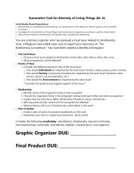
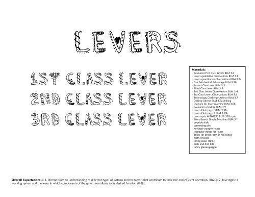
Levers<br />
<strong>1st</strong> <strong>class</strong> <strong>lever</strong><br />
<strong>2nd</strong> <strong>class</strong> <strong>lever</strong><br />
<strong>3rd</strong> <strong>class</strong> <strong>lever</strong><br />
Materials:<br />
- Resources First Class Levers BLM 3.0<br />
- Levers qualitative observations BLM 3.1<br />
- Levers quantitative observations BLM 3.2a<br />
- Calc Mechanical Advantage BLM 3.2b<br />
- Second Class Lever BLM 3.3<br />
- Third Class Lever BLM 3.5<br />
- <strong>2nd</strong> Class Levers Observations BLM 3.4<br />
- <strong>3rd</strong> Class Levers Observations BLM 3.6<br />
- Technology Challenge-Askmar BLM 3.7<br />
- Drilling Scheme BLM 3.8a drilling<br />
- Diagram for <strong>lever</strong> machine BLM 3.8b<br />
- Evaluation checklist BLM 3.9<br />
- Levers Quiz page 1 BLM 3.10a<br />
- Levers Quiz page 2 BLM 3.10b<br />
- Levers quiz ANSWERS BLM 3.10c quiz<br />
- Word Search Simple Machines BLM 3.11<br />
- popsicle sticks<br />
- connecting pins<br />
- notched wooden <strong>lever</strong>s<br />
- triangular stands for <strong>lever</strong>s<br />
- bricks (or other form of resistance)<br />
- metric masses<br />
- spring scales (10 N)<br />
- drills and drill bits<br />
- safety glasses/goggles<br />
Overall Expectation(s): 3. Demonstrate an understanding of different types of systems and the factors that contribute to their safe and efficient operation. (8s20); 2. Investigate a<br />
working system and the ways in which components of the system contribute to its desired function (8s19).
Structures and Mechanisms – Systems in Action<br />
– <strong>1st</strong> Class Levers –<br />
Description: During this subtask, the students will review the three <strong>class</strong>es of <strong>lever</strong>s. They students will have the opportunity to<br />
observe, discover, and investigate <strong>lever</strong>s and their practical applications and to apply their previous knowledge to practical<br />
applications and situations. The students will investigate ways of linking different <strong>class</strong>es <strong>lever</strong>s to a system, as a way of<br />
improving the performance of that system<br />
Activity 1 - First Class Levers<br />
Part #1 (Qualitative)<br />
1. Place the <strong>lever</strong> on the fulcrum so the fulcrum is in the centre groove. (BLM 3.0 - Diagram 1)<br />
2. Place the brick (resistance/load) on one end of the <strong>lever</strong>. Move the <strong>lever</strong> so the fulcrum is close to the resistance.<br />
3. Have the students push down on the other end of the <strong>lever</strong> using their hands as the effort force.<br />
4. Record these observations on the chart. (Blackline master BLM 3.1)<br />
5. Repeat this procedure by moving the fulcrum to the centre of the load, then closer to the effort. Record observations<br />
each time.<br />
Part #2 (Quantitative)<br />
1. Place the <strong>lever</strong> on the fulcrum so the fulcrum is in the centre groove. The effort arm should be overhanging the desk<br />
(BLM 3.0 - Diagram 2)<br />
2. Place a measured resistance, 200 g weight, on one end of the <strong>lever</strong>. Position the <strong>lever</strong> so the fulcrum is close to the<br />
resistance.<br />
3. Hook a Newton spring scale over the end of the <strong>lever</strong>. (Note: AN eye hook may be placed under the end of the <strong>lever</strong><br />
to anchor the spring scale.)<br />
4. Record the effort needed to lift the resistance. (see blackline master BLM 3.2a)<br />
5. Repeat the procedure by moving the fulcrum to the centre of <strong>lever</strong> and the close to the effort. The fulcrum is moving<br />
away from the resistance and closer to the effort. Again, record the force (effort) necessary to move the resistance.<br />
6. Have the students calculate the mechanical advantage of a first <strong>class</strong> <strong>lever</strong> by altering the resistance arm and the effort<br />
arm using two 200 g weights. Students will change the distance of the arms four times and calculate the resulting<br />
Mechanical Advantage.<br />
7. Record the measurement of distances of each arm in the appropriate box on table BLM 3.2b. Then have students<br />
calculate Mechanical Advantage and write in the correct response in the corresponding box on table BLM 3.2b.<br />
Note: The students should notice that during this activity there is a change in direction of the forces.
Things to remember about machines:<br />
All machines, no matter how complex or how simple they are, contain one or more of the simple machines.<br />
There are six simple machines:<br />
1. Lever<br />
2. Wheel and Axle<br />
3. Pulley<br />
4. Inclined Plane<br />
5. Wedge<br />
6. Screw<br />
(If you look carefully at this list you will notice that the wheel and axle and the pulley are extensions of the ever.<br />
You will also notice that the wedge and the screw are different forms of the inclined plane.) Generally speaking<br />
machines are devices invented to help a person work a little bit easier. Machines are very useful from four<br />
perspectives. They can transfer a force from one place to another; take a force and change its direction; take a<br />
small force and increase this force to lift heavy objects which could not be lifted without a machine; move objects<br />
further and faster by increasing the distance and speed of a force.<br />
Note: No machine will increase both force and distance at the same time. One will come at the expense of the<br />
other. Think about it this way - If you apply a small force to a heavy object and it moves, however, you will only<br />
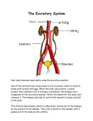
be able to move it a short distance.<br />
Things to remember about <strong>lever</strong>s:<br />
Lever: a rigid bar or rod that pivots at a fixed point.<br />
Fulcrum: a fixed point, or point at which the <strong>lever</strong> pivots.<br />
Effort: a force exerted or applied to the <strong>lever</strong>.<br />
Resistance: a force that the <strong>lever</strong> exerts on the object (the load).<br />
Effort arm: the distance between the fulcrum and the effort force.<br />
Resistance arm: the distance between the object or the resistance force and the fulcrum.<br />
Remember with a first <strong>class</strong> <strong>lever</strong>, the closer you move the fulcrum to the resistance or object you are trying to<br />
move, the less effort force you will have to apply. However, as previously discussed, the effort distance will move<br />
a greater distance and the resistance will move a shorter distance. If you move the fulcrum closer to the effort, you<br />
will need a greater force to move the resistance. However, this time you will make the effort distance shorter and<br />
the resistance will move a greater distance. If this seems somewhat confusing, reread the previous few points and<br />
blackline masters: BLM 3.0, BLM 3.3 & BLM 3.5 in sight. (The first three activities will demonstrate and reinforce<br />
this point.) First <strong>class</strong> <strong>lever</strong>s occur when the fulcrum is placed anywhere between the effort and the resistance.<br />
Second <strong>class</strong> <strong>lever</strong>s occur when the resistance is between the fulcrum and effort. Third <strong>class</strong> <strong>lever</strong>s occur when the<br />
effort is between the fulcrum and the resistance.
Structures and Mechanisms – Systems in Action<br />
– <strong>2nd</strong> Class Levers –<br />
Description: During this subtask, the students will review the three <strong>class</strong>es of <strong>lever</strong>s. They students will have the opportunity to<br />
observe, discover, and investigate <strong>lever</strong>s and their practical applications and to apply their previous knowledge to practical<br />
applications and situations. The students will investigate ways of linking different <strong>class</strong>es <strong>lever</strong>s to a system, as a way of<br />
improving the performance of that system<br />
Activity 2 - Second Class Levers<br />
(Note: Attach eye hooks to the top of the <strong>lever</strong>, as an anchor for the Newton spring scale.)<br />
1. Position the resistance (load) between the fulcrum and the effort. Start by placing the resistance (load) close to the<br />
fulcrum. (See blackline master BLM 3.3)<br />
2. Have students apply the effort first using their hands (qualitative), then using the Newton spring scale. Record both<br />
qualitative and quantitative observations. (See blackline master BLM 3.4)<br />
3. Repeat this procedure, first by moving the resistance to the centre of the <strong>lever</strong>, then close to the effort. (Note: the<br />
resistance is moving away from the fulcrum towards the effort.)<br />
4. Record your observations.<br />
Note: Students should note that the second <strong>class</strong> <strong>lever</strong> does not change the direction of the force. Both the effort and the<br />
resistance move upward.
Things to remember about machines:<br />
All machines, no matter how complex or how simple they are, contain one or more of the simple machines.<br />
There are six simple machines:<br />
1. Lever<br />
2. Wheel and Axle<br />
3. Pulley<br />
4. Inclined Plane<br />
5. Wedge<br />
6. Screw<br />
(If you look carefully at this list you will notice that the wheel and axle and the pulley are extensions of the ever.<br />
You will also notice that the wedge and the screw are different forms of the inclined plane.) Generally speaking<br />
machines are devices invented to help a person work a little bit easier. Machines are very useful from four<br />
perspectives. They can transfer a force from one place to another; take a force and change its direction; take a<br />
small force and increase this force to lift heavy objects which could not be lifted without a machine; move objects<br />
further and faster by increasing the distance and speed of a force.<br />
Note: No machine will increase both force and distance at the same time. One will come at the expense of the<br />
other. Think about it this way - If you apply a small force to a heavy object and it moves, however, you will only<br />
be able to move it a short distance.<br />
Things to remember about <strong>lever</strong>s:<br />
Lever: a rigid bar or rod that pivots at a fixed point.<br />
Fulcrum: a fixed point, or point at which the <strong>lever</strong> pivots.<br />
Effort: a force exerted or applied to the <strong>lever</strong>.<br />
Resistance: a force that the <strong>lever</strong> exerts on the object (the load).<br />
Effort arm: the distance between the fulcrum and the effort force.<br />
Resistance arm: the distance between the object or the resistance force and the fulcrum.<br />
Remember with a first <strong>class</strong> <strong>lever</strong>, the closer you move the fulcrum to the resistance or object you are trying to<br />
move, the less effort force you will have to apply. However, as previously discussed, the effort distance will move<br />
a greater distance and the resistance will move a shorter distance. If you move the fulcrum closer to the effort, you<br />
will need a greater force to move the resistance. However, this time you will make the effort distance shorter and<br />
the resistance will move a greater distance. If this seems somewhat confusing, reread the previous few points and<br />
blackline masters: BLM 3.0, BLM 3.3 & BLM 3.5 in sight. (The first three activities will demonstrate and reinforce<br />
this point.) First <strong>class</strong> <strong>lever</strong>s occur when the fulcrum is placed anywhere between the effort and the resistance.<br />
Second <strong>class</strong> <strong>lever</strong>s occur when the resistance is between the fulcrum and effort. Third <strong>class</strong> <strong>lever</strong>s occur when the<br />
effort is between the fulcrum and the resistance.
Structures and Mechanisms – Systems in Action<br />
– <strong>3rd</strong> Class Levers –<br />
Activity 3 - Third Class Levers<br />
1. Set up the third <strong>class</strong> <strong>lever</strong> (see blackline master BLM 3.5), with the effort between the fulcrum and the resistance.<br />
2. Starting with the effort closer to the fulcrum, use the eye hooks as an anchor for the Newton spring scale. Record both<br />
qualitative and quantitative observations. (see blackline master BLM 3.6)<br />
3. Repeat this procedure with the effort in the the centre of the <strong>lever</strong>. Record your observations.<br />
4. Repeat this procedure with the effort closer to load. Record your observations.<br />
Note: The students may have to hold down on the <strong>lever</strong> just above the fulcrum to prevent the <strong>lever</strong> from being lifted up.<br />
Students should note that the third <strong>class</strong> <strong>lever</strong> also does not change the direction of the force.<br />
Activity 4 - Performance Task<br />
Provide the students with copies of BLM 3.7 - pages 1 to 4 and review the SPICE Model BLM 3.7 - page 1.<br />
1. The students will be given the rescue situation. Refer to the Technology Challenge - Help the Askmar (BLM 3.7).<br />
2. Each student will receive six popsicle sticks and seven connecting pins.<br />
3. Two of those six popsicle sticks will be drilled with a ¼ inch drill bit. One at either end. Drill one in the middle.<br />
4. Each of the remaining four Popsicle sticks are to be drilled in the middle and at one of the ends (see blackline master<br />
BLM 3.8a)<br />
5. Assemble the "space" arm as per the diagram (BLM 3.8b).<br />
6. Upon completion the student will be given the task of retrieving the 200 g weight (Askmar), bringing it back across n<br />
open span of 16 cm (water).
Things to remember about machines:<br />
All machines, no matter how complex or how simple they are, contain one or more of the simple machines.<br />
There are six simple machines:<br />
1. Lever<br />
2. Wheel and Axle<br />
3. Pulley<br />
4. Inclined Plane<br />
5. Wedge<br />
6. Screw<br />
(If you look carefully at this list you will notice that the wheel and axle and the pulley are extensions of the ever.<br />
You will also notice that the wedge and the screw are different forms of the inclined plane.) Generally speaking<br />
machines are devices invented to help a person work a little bit easier. Machines are very useful from four<br />
perspectives. They can transfer a force from one place to another; take a force and change its direction; take a<br />
small force and increase this force to lift heavy objects which could not be lifted without a machine; move objects<br />
further and faster by increasing the distance and speed of a force.<br />
Note: No machine will increase both force and distance at the same time. One will come at the expense of the<br />
other. Think about it this way - If you apply a small force to a heavy object and it moves, however, you will only<br />
be able to move it a short distance.<br />
Things to remember about <strong>lever</strong>s:<br />
Lever: a rigid bar or rod that pivots at a fixed point.<br />
Fulcrum: a fixed point, or point at which the <strong>lever</strong> pivots.<br />
Effort: a force exerted or applied to the <strong>lever</strong>.<br />
Resistance: a force that the <strong>lever</strong> exerts on the object (the load).<br />
Effort arm: the distance between the fulcrum and the effort force.<br />
Resistance arm: the distance between the object or the resistance force and the fulcrum.<br />
Remember with a first <strong>class</strong> <strong>lever</strong>, the closer you move the fulcrum to the resistance or object you are trying to<br />
move, the less effort force you will have to apply. However, as previously discussed, the effort distance will move<br />
a greater distance and the resistance will move a shorter distance. If you move the fulcrum closer to the effort, you<br />
will need a greater force to move the resistance. However, this time you will make the effort distance shorter and<br />
the resistance will move a greater distance. If this seems somewhat confusing, reread the previous few points and<br />
blackline masters: BLM 3.0, BLM 3.3 & BLM 3.5 in sight. (The first three activities will demonstrate and reinforce<br />
this point.) First <strong>class</strong> <strong>lever</strong>s occur when the fulcrum is placed anywhere between the effort and the resistance.<br />
Second <strong>class</strong> <strong>lever</strong>s occur when the resistance is between the fulcrum and effort. Third <strong>class</strong> <strong>lever</strong>s occur when the<br />
effort is between the fulcrum and the resistance.
BLM 3.1<br />
Fulcrum close to the<br />
resistance<br />
Fulcrum in the centre<br />
Fulcrum close to the effort<br />
Student Notes:<br />
Copyright: Thames Valley District School Board, 1999<br />
Page 46 of 120<br />
Observations<br />
(Recording what you feel)<br />
QUALITATIVE (Observations)
BLM 3.2a<br />
Fulcrum close to the<br />
resistance<br />
Fulcrum in the centre<br />
Fulcrum close to the effort<br />
Student Notes:<br />
Copyright: Thames Valley District School Board, 1999<br />
Page 47 of 120<br />
Observations<br />
(Recording what you see)<br />
QUANTITATIVE (# of Newtons)
BLM 3.2b<br />
Trial<br />
1<br />
2<br />
3<br />
4<br />
Student Notes:<br />
Copyright: Thames Valley District School Board, 1999<br />
CALCULATING MECHANICAL ADVANTAGE<br />
Distance of<br />
Resistance Arm<br />
from the fulcrum (cm)<br />
Page 48 of 120<br />
Distance of<br />
Effort Arm<br />
from the fulcrum (cm)<br />
Mechanical<br />
Advantage<br />
(MA)
Effort<br />
Copyright: Thames Valley District School Board, 1999<br />
Page 49 of 120<br />
Second Class Levers<br />
Resistance<br />
BLM 3.3
BLM 3.4 Second Class Levers<br />
Resistance close to the<br />
fulcrum<br />
Resistance in the centre<br />
Resistance close to the<br />
effort<br />
Student Notes:<br />
Copyright: Thames Valley District School Board, 1999<br />
Page 50 of 120<br />
Observations<br />
(Qualitative and Quantitative)<br />
QUALITATIVE<br />
(Observations)<br />
QUANTITATIVE<br />
(# of Newtons)
Copyright: Thames Valley District School Board, 1999<br />
Page 51 of 120<br />
Third Class Levers<br />
Resistance Effort Effort Effort<br />
BLM 3.5
BLM 3.6 Third Class Levers<br />
Effort close to the<br />
fulcrum<br />
Effort in the centre<br />
Effort close to the<br />
resistance<br />
Student Notes:<br />
Copyright: Thames Valley District School Board, 1999<br />
Page 52 of 120<br />
Observations<br />
(Qualitative and Quantitative)<br />
QUALITATIVE<br />
(Observations)<br />
QUANTITATIVE<br />
(# of Newtons)
SPICE MODEL<br />
–<br />
–<br />
–<br />
–<br />
BLM 3.7 Page 1 of 4<br />
S = SITUATION<br />
Observe the scene. Look for problems or possibilities. Consider what has<br />
happened to create the problem.<br />
P = PROBLEMS AND POSSIBILITIES<br />
Clarify and define what the problem is and what the possible solutions to the<br />
problem might be.<br />
I = INVESTIGATION / IDEAS<br />
Brainstorm as many solutions to the problem as possible. Research each idea.<br />
Consider the factors such as resources, equipment, costs, skills.<br />
C = CHOOSE / CONSTRUCT<br />
Choose the idea which you consider the best after considering all of the<br />
contributing factors. Plan and construct. Test when necessary as you proceed.<br />
E = EVALUATE<br />
Look back at the problem and reflect on how well the requirements were achieved<br />
in your solution. Consider improvements.<br />
** This method of design is not linear. “Backtracking” will occur in most design problems the<br />
need to revise, move back in the process or to begin again is common in innovation.<br />
“Sidetrips” will need to be taken during the process as well; these involve seeking clarification,<br />
doing research and solving mini-problems.<br />
Copyright: Thames Valley District School Board, 1999<br />
Page 53 of 120<br />
Adapted from the SPICE model created by Geoff Day, University of Toronto, 1989
TECHNOLOGY CHALLENGE<br />
Name: Date:<br />
Problem and Possibilities:<br />
Ideas:<br />
Design #1 Design #2<br />
BLM 3.7 Page 2 of 4<br />
Situation: Help the Askmar (Year 3000 the New Millennium)<br />
You have just spent a week at an all expenses paid science conference on Mars. The conference was a gathering<br />
of the minds. Top scientists were gathered together sharing information on the three <strong>class</strong>es of <strong>lever</strong>s and three practical<br />
applications. Upon returning to earth your spaceship experienced technical difficulties. You crash landed on an uncharted<br />
planet where you found a primitive group of people who are in a bit of a bind. The Askmar, a sacred burial mask, had<br />
been stolen by a rival tribe and placed on the island of Winpact. Unfortunately, the island is totally surrounded by water<br />
and the primitive group does not have the technology to recover the Askmar. Can you help? In your ship you are<br />
equipped with only a few Popsicle sticks, a drill, a few connecting pins, and your vast knowledge of <strong>lever</strong>s. You must<br />
prove to them that you can save the Askmar.<br />
Copyright: Thames Valley District School Board, 1999<br />
Page 54 of 120
Equipment needed: Equipment needed:<br />
Design # was chosen because<br />
Choose / Construct: (step by step procedure)<br />
Observations:<br />
Copyright: Thames Valley District School Board, 1999<br />
Page 55 of 120<br />
BLM 3.7 Page 3 of 4
Evaluate:<br />
Some of the challenges were:<br />
Possible change(s) for next time would be<br />
because<br />
This device would be useful for<br />
I am proud of my design because<br />
Copyright: Thames Valley District School Board, 1999<br />
Page 56 of 120<br />
Page 4 of 4
Copyright: Thames Valley District School Board, 1999<br />
Page 58 of 120<br />
Diagram for Lever Machine<br />
BLM 3.8B
BLM 3.9<br />
Student’s Name: __________________________<br />
Date: ___________________________________<br />
Evaluation checklist for small groups<br />
1. Works co-operatively with others 1 2 3 4<br />
2. Considers all facts before drawing conclusions 1 2 3 4<br />
3. Shows respect for others 1 2 3 4<br />
4. Listens to others without interrupting 1 2 3 4<br />
5. Volunteers information 1 2 3 4<br />
6. Supports group’s ideas with facts 1 2 3 4<br />
7. Contributes well when called upon 1 2 3 4<br />
8. Stays on task 1 2 3 4<br />
9. Willing to have ideas challenged 1 2 3 4<br />
10. Willing to make necessary changes as facts are presented 1 2 3 4<br />
FURTHER COMMENTS:<br />
Copyright: Thames Valley District School Board, 1999<br />
Page 59 of 120
BLM 3.10a<br />
Levers Quiz<br />
1. Why do we choose to use simple machines? __________________________<br />
_____________________________________________________________<br />
2. List the six kinds of simple machines.<br />
__________________________ _________________________<br />
__________________________ _________________________<br />
__________________________ _________________________<br />
3. How does a <strong>lever</strong> work? _________________________________________<br />
_____________________________________________________________<br />
4. Define the following terms:<br />
a. Resistance force __________________________________________<br />
b. Effort force ______________________________________________<br />
c. Effort distance ____________________________________________<br />
5. What is mechanical advantage? __________________________________<br />
____________________________________________________________<br />
6. How do all simple machines help to make work easier?<br />
____________________________________________________________<br />
____________________________________________________________<br />
7. List three examples of each of the three types of <strong>lever</strong>s.<br />
____________________________________________________________<br />
____________________________________________________________<br />
____________________________________________________________<br />
Practical Application<br />
List three other practical applications of your “space” arm and describe their use.<br />
___________________________________________________________________<br />
___________________________________________________________________<br />
________________________________________________________________<br />
___________________________________________________________________<br />
___________________________________________________________________<br />
___________________________________________________________________<br />
___________________________________________________________________<br />
______________________________________________________________<br />
Copyright: Thames Valley District School Board, 1999<br />
Page 60 of 120
Application<br />
Copyright: Thames Valley District School Board, 1999<br />
Page 61 of 120<br />
Levers Quiz<br />
10 20 30 40 60 70 80 90<br />
Questions<br />
BLM 3.l0b<br />
200 g 100 g<br />
1. What is the distance between the balance point and the 100g weight?<br />
2. What is the mechanical advantage of this first <strong>class</strong> <strong>lever</strong> system?<br />
3. Divide 200g by 100g. What is your answer?<br />
4. How closely does the mechanical advantage compare to the ratio of the two masses?
BLM 3.10c<br />
LEVERS QUIZ (possible answers)<br />
1. We use simple machines to try to make our work a little easier.<br />
Page 1 of 2<br />
2. The six types of simple machines are LEVER, WHEEL & AXLE, PULLEY, INCLINED<br />
PLANE, WEDGE, and SCREW.<br />
3. A <strong>lever</strong> works by changing the amount of force that you must exert in order to move an<br />
object.<br />
4. Resistance force is the force the <strong>lever</strong> exerts on the object.<br />
Effort force is the force exerted or applied to the <strong>lever</strong>.<br />
Effort distance is the distance between the fulcrum and the effort force.<br />
5. Mechanical Advantage is the RATIO of the force produced by the LOAD (Resistance) to<br />
the force applied by the EFFORT. Students must always remember that the units for both<br />
Load and Effort must be the same.<br />
6. All simple machines help to make work easier by transferring a force from one place to<br />
another.<br />
7. The following are examples of each type of <strong>lever</strong>:<br />
FIRST CLASS: seesaw, scissors, pliers, hedge clippers<br />
SECOND CLASS: wheelbarrow, standing on your tip toes, fridge cart<br />
THIRD CLASS: tweezers, shooting a puck with a hockey stick, picking up something<br />
between your thumb & forefinger<br />
PRACTICAL APPLICATION (answers will vary)<br />
Example 1: A factory could have an arm that could reach across equipment to pick up supplies a<br />
worker might need so the worker would not have to continually walk around machinery to get<br />
supplies.<br />
Example 2: People in a boat could use the arm to reach into the water to collect garbage, so they<br />
do not have to actually get in the water to collect it.<br />
Example 3: Pool maintenance people could use it to add chemicals to the water. Since they would<br />
not have to get close to the pool, the chemicals would not splash up onto their skin and burn<br />
them.<br />
Copyright: Thames Valley District School Board, 1999<br />
Page 62 of 120
APPLICATION QUESTIONS<br />
Page 2 of 2<br />
1. The distance between the balance point and the 100g weight is 90 units - 50 units = 40<br />
units.<br />
2. The mechanical advantage of this first <strong>class</strong> <strong>lever</strong> is<br />
Load (Resistance) ÷ Effort<br />
= 200 g ÷ 100 g<br />
= 2<br />
3. 200 ÷ 100 = 2<br />
4. Mechanical Advantage is the comparison of the two masses so therefore, the answers to<br />
questions 2 & 3 are exactly the same.<br />
Copyright: Thames Valley District School Board, 1999<br />
Page 63 of 120