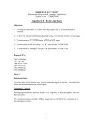
Course notes - Myweb.dal.ca - Dalhousie University
Course notes - Myweb.dal.ca - Dalhousie University
Course notes - Myweb.dal.ca - Dalhousie University

Create successful ePaper yourself
Turn your PDF publications into a flip-book with our unique Google optimized e-Paper software.
IC Design and Fabri<strong>ca</strong>tion<br />
ECED 4260<br />
Switch<br />
Switch<br />
Switch<br />
Matrix<br />
Matrix<br />
Matrix<br />
Switch<br />
Matrix<br />
CLB<br />
Switch<br />
Matrix<br />
CLB<br />
CLB CLB<br />
Switch<br />
Matrix<br />
Switch<br />
Switch<br />
Switch<br />
Matrix<br />
Matrix<br />
Matrix<br />
Jason GU<br />
Electri<strong>ca</strong>l and Computer Comp ter Engineering<br />
<strong>Dalhousie</strong> <strong>University</strong><br />
Halifax. NS B3J 2X4<br />
Canada<br />
Sept. 5 2012
Part 1. Review of<br />
Classi<strong>ca</strong>l Sequential<br />
Logic Design<br />
• 1.1 Introduction to Combinational<br />
Logic<br />
• 1.2 Boolean Algebra<br />
• 1.3 Mixed Logic<br />
• 1.4 Algebraic Specifi<strong>ca</strong>tion of<br />
Combinational Logic<br />
• 1.5 Memory Elements<br />
• 1.6 Synthesis Procedure<br />
• 1.7: Introduction to Programmable<br />
Logic Devices (PLDs)<br />
1
V in<br />
V out<br />
1.1 Introduction to<br />
Combinational Logic<br />
Logic Symbole for inverter:<br />
V in<br />
Truth Table<br />
V in<br />
V out<br />
Dynamic Behavior:<br />
Analog view<br />
V out<br />
t<br />
t<br />
V out<br />
V in<br />
2
1.1 Introduction to<br />
Combinational<br />
Logic(cont’d)<br />
Logic gates: single input<br />
Black box<br />
Input Output<br />
A F1 F2 F3 F4<br />
L L L H H<br />
H L H L H<br />
What are these functions?<br />
3
1.1 Introduction to<br />
Combinational Logic<br />
(cont’d)<br />
Logic gates: Two input<br />
Input<br />
Black box<br />
Output<br />
A B F1 F2 F3 F4 F5 F6 F7 F8 F9 F10 F11 F12 F13 F14 F15 F16<br />
L L L L L H<br />
L H L L L H<br />
H L L L H H<br />
H H L H L H<br />
What are these functions?<br />
4
1.1 Introduction to<br />
Combinational Logic<br />
(cont’d)<br />
Logic gates: Multiple input<br />
X1<br />
X2<br />
X N<br />
...<br />
Black box<br />
If X1=X2=...=XN=H, then F=H; otherwise, F=L.<br />
If X1=X2=...=XN=L, then F=L; otherwise, F=H.<br />
If X1=X2=...=XN=H, then F=L; otherwise, F=H.<br />
If X1=X2=...=XN=L, then F=H; otherwise, F=L.<br />
If an odd number of Xi are H, then F=H; otherwise, F=L.<br />
If an even number of Xi are H, then F=H; otherwise, F=L.<br />
What are these functions?<br />
F<br />
5
1.1 Introduction to<br />
Combinational Logic<br />
(cont’d) Remarks:<br />
• After all signals have stabilized, the<br />
present output signals are entirely<br />
determined by the present input<br />
signals<br />
• Combinational logic has no memory<br />
of past inputs<br />
• Combinational logic <strong>ca</strong>n always be<br />
implemented as a network of basic<br />
logic gates<br />
• Typi<strong>ca</strong>lly there are no signal paths<br />
that loop back on themselves.<br />
6
X1<br />
X2<br />
X N<br />
1.1 Introduction to<br />
Combinational Logic:<br />
Time diagram:<br />
X1---X N<br />
Y1---Y M<br />
(cont’d) :<br />
Combinational<br />
Logic<br />
Y1<br />
Y2<br />
Y M<br />
7
1.1 Introduction to<br />
Combinational Logic:<br />
Example 1.1<br />
Example: Design a 3-input NXOR gate using only<br />
NOT, AND and OR gates.<br />
Behavior:<br />
Truth Table:<br />
X1 X2 X3 F<br />
L L L H<br />
L L H L<br />
L H L L<br />
L H H H<br />
H L L L<br />
H L H H<br />
H H L H<br />
H H H L<br />
x1 x2 x3<br />
8<br />
F
1.2 Boolean Algebra(1)<br />
• A)There is a set S of possible values.<br />
Set S must contain at least two special<br />
values, which is denoted by 0 and 1<br />
• B) There are two binary operations,<br />
• . and +, that <strong>ca</strong>n be applied to pairs of<br />
elements from S to produce elements<br />
from S.<br />
• C) operations . and + are<br />
commutative. i.e. For a, b∈ S<br />
a+b=b+a and a.b=b.a<br />
9
1.2 Boolean Algebra(2)<br />
• D) operations . and + distribute<br />
over one another.<br />
• a.(b+c)=(a.b)+(a.c)<br />
• a+(b.c)=(a+b).(a+c)<br />
• Elements 0 and 1 are identities<br />
for + and . respectively.<br />
• 0+a=a and 1.a=a<br />
• For each element, a ∈ S there<br />
exists an element a ∈ S such<br />
that a + a = 1 and a. a =<br />
0<br />
10
1.2 Boolean Algebra:<br />
Theorem<br />
• Idempotent: a+a=a a.a=a<br />
• Null elements: a+1=1 a.0=0<br />
• Involution a = a<br />
• Absorption: a+(a.b)=a a.(a+b)=a<br />
• Associativity:<br />
• a+(b+c)=(a+b)+c<br />
• a.(b.c)=(a.b).c<br />
• DeMorgan:<br />
a + b = a . b , a n d a . b = a +<br />
b<br />
11
1.2 Boolean Algebra:<br />
Theorem (cont’d)<br />
• Adjacency: a.b+a. b=a<br />
• (a+b).(a+ b )=a<br />
• Consensus:<br />
• (a.b)+(b.c)+( a.c)=(a.b)+( a.c)<br />
• Duality: the dual of Boolean<br />
equation is the equation obtained by<br />
interchanging all .’s and +’s, and<br />
interchanging all 0’s and 1’s<br />
• Principle of duality: A Boolean<br />
equation is true if and only if the<br />
dual Boolean equation is true<br />
12
1.3 Mixed Logic<br />
• Draw backs of entirely positive or<br />
negative logic conventions:<br />
– The rules for synthesizing and<br />
analyzing multiple level NAND/NOR<br />
networks from AND/OR networks are<br />
compli<strong>ca</strong>ted<br />
– It is difficult sometimes to read off<br />
Boolean equations from a circuit<br />
diagram that uses only positive logic<br />
– Mixed logic is the practice of using<br />
both positive and negative signal<br />
encoding on the same circuit diagram.<br />
– Mixed logic is also <strong>ca</strong>lled “direct<br />
polarity indi<strong>ca</strong>tion”<br />
– If used properly, mixed logic <strong>ca</strong>n<br />
improve the readability of circuit<br />
diagrams.<br />
13
1.3 Mixed Logic: Main<br />
Ideas<br />
• The shape of a gate symbol<br />
should reflect the logi<strong>ca</strong>l<br />
function<br />
• Bubbles are used on all inputs<br />
and outputs to indi<strong>ca</strong>te how<br />
Boolean 0’s and 1’s are encoded<br />
using physi<strong>ca</strong>l L’s and H’s<br />
– No bubble positive logic<br />
– Bubble negative logic<br />
14
1.3 Mixed Logic:<br />
Logic<br />
signal<br />
A<br />
B<br />
C<br />
Notations<br />
Positive<br />
logic<br />
A.H<br />
B(H)<br />
C<br />
Negative<br />
logic<br />
A.L<br />
B(L)<br />
C/<br />
D D . H D . L<br />
15
AND gates:<br />
A.H<br />
B.H<br />
A(L)<br />
B(L)<br />
OR gates:<br />
A.H<br />
B.H<br />
A(L)<br />
B(L)<br />
1.3 Mixed Logic:<br />
Example 1.2<br />
C.H<br />
C.H<br />
A(H)<br />
B(H)<br />
A.H<br />
C(H)<br />
B.L<br />
C=A.B<br />
A(H)<br />
B(H)<br />
A.H<br />
C(H)<br />
B.L<br />
C=A+B<br />
C(L)<br />
C.L<br />
C(L)<br />
C.L<br />
16
1.4 Algebraic<br />
Specifi<strong>ca</strong>tion of<br />
Combinational Logic<br />
• Definitions<br />
– A literal is a variable or its<br />
complement form<br />
– A minterm of n variables is<br />
product of n literals in which each<br />
variable appears exactly once in<br />
either true or complement form<br />
– A maxterm if n variable is a sum<br />
of n literals in which each<br />
variable appears exactly once in<br />
either true or complement form.<br />
17
1.4 Algebraic<br />
Specifi<strong>ca</strong>tion of<br />
Combinational Logic<br />
1). Boolean Function Truth Table<br />
Mi<br />
0<br />
1<br />
2<br />
3<br />
4<br />
5<br />
6<br />
7<br />
X1 X2 X3 F<br />
0 0 0 0<br />
0 0 1 1<br />
0 1 0 1<br />
0 1 1 0<br />
1 0 0 1<br />
1 0 1 0<br />
1 1 0 0<br />
1 1 1 1<br />
2) As a sum of minterms:<br />
( )<br />
F X 1 ,X 2 ,X 3 =m +m +m +m<br />
1 2 4 7<br />
( )<br />
3) As a product of maxterms<br />
F X 1 ,X 2 ,X 3 =M +M +M +M<br />
0 3 5 6<br />
X1 X2 X3 F<br />
L L L L<br />
L L H H<br />
L H L H<br />
L H H L<br />
H L L H<br />
H L H L<br />
H H L L<br />
H H H H<br />
= X1 X 2 X + X 1 X X 3 +X X 2 X 3 +X X X<br />
3 2 1 1 2 3<br />
=(X1+X2+X3)(X1+ X2 + X3)(X1+X2+ X3)(X1+ X2 +X3)<br />
18
1.4.1 Simplifi<strong>ca</strong>tion of<br />
Boolean Functions<br />
• Motivation:<br />
– Simpler circuit, fewer gates, save<br />
money<br />
• Definition<br />
– Impli<strong>ca</strong>nts: a group of 2 n adjacent 1’s in<br />
a k-map.<br />
– Prime impli<strong>ca</strong>nt: an impli<strong>ca</strong>nt that<br />
<strong>ca</strong>nnot be doubled in size by applying<br />
the adjacency theorem<br />
– Minimum cover: smallest set of prime<br />
impli<strong>ca</strong>nts that covers all the 1’s or 0’s<br />
– Minimum S.O.P: a sum of products that<br />
corresponding to a minimum cover of<br />
the 1’s<br />
– Minimum P.O.S: a product of sums that<br />
corresponds to a minimum cover of the<br />
0’s<br />
19
1.4.2 Karnaugh Maps<br />
– A Karnaugh Map is a binary truth<br />
table in which the function values<br />
are arranged to facilitate the<br />
visual detection of of logi<strong>ca</strong>l<br />
relationships and therefore the<br />
manual appli<strong>ca</strong>tion of the laws<br />
and theorems of Boolean Algebra<br />
– Find the F of following:<br />
BC<br />
A<br />
00<br />
01<br />
11<br />
10<br />
0 1<br />
1 0<br />
1 1<br />
0 1<br />
0 0<br />
20
A B C D W X Y Z<br />
0 0 0 0 0 0 0 1 1<br />
1 0 0 0 1 0 1 0 0<br />
2 0 0 1 0 0 1 0 1<br />
3 0 0 1 1 0 1 1 0<br />
4 0 1 0 0 0 1 1 1<br />
5 0 1 0 1 1 0 0 0<br />
6 0 1 1 0 1 0 0 1<br />
7 0 1 1 1 1 0 1 0<br />
8 1 0 0 0 1 0 1 1<br />
9 1 0 0 1 1 1 0 0<br />
1 0 1 0<br />
1 0 1 1<br />
1 1 0 0<br />
1 1 0 1<br />
1 1 1 0<br />
1 1 1 1<br />
1.4.2 Example 1.3<br />
• Design a two-level combinational<br />
circuit that converts from binary<br />
coded decimal(BCD) to excess 3<br />
code<br />
AB<br />
CD<br />
00<br />
01<br />
11<br />
10<br />
AB<br />
CD<br />
00<br />
01<br />
11<br />
10<br />
00 01 11 10<br />
00 01 11 10<br />
1 1 1<br />
0 0 0<br />
1 1<br />
0 0<br />
AB<br />
CD<br />
00<br />
01<br />
11<br />
10<br />
W X<br />
AB<br />
CD<br />
00<br />
01<br />
11<br />
10<br />
Y Z<br />
00 01 11 10<br />
0 1 0<br />
1 0 1<br />
1 0<br />
1 0<br />
00 01 11 10<br />
1 1 1<br />
0 0 0<br />
0 0<br />
1 1<br />
21
A A<br />
B B<br />
C C<br />
D D<br />
B<br />
C<br />
B<br />
D<br />
B<br />
C<br />
D<br />
C<br />
D<br />
C D<br />
D<br />
1.4.2 Example 1.3<br />
• Design a two-level combinational<br />
circuit that converts from binary<br />
coded decimal(BCD) to excess 3<br />
code<br />
X<br />
Y<br />
Z<br />
W =<br />
X=BC+BD+BCD<br />
( )( )<br />
Y= C+D C+D<br />
Z= D<br />
22
1.5 Memory Elements:<br />
SR latches:<br />
JK Flip-Flop:<br />
D Flip-Flop:<br />
Latches<br />
23
1.5 Sequential Logic:<br />
Remarks<br />
• After all signals have stabilized,<br />
present output signals are<br />
determined by both the present and<br />
past input signals<br />
• Circuit has closed loops with<br />
implement memory elements.<br />
• Two class of sequential logic:<br />
– Synchronous sequential logic: a timing<br />
signal is used.<br />
– Asynchronous sequential logic: no<br />
timing signal is used. The memory<br />
elements are free to change state<br />
immediately after input signals change<br />
24
1.5 Sequential Logic:<br />
Remarks (cont’d)<br />
• General structure of a sequential<br />
circuit:<br />
INPUT OUTPUT<br />
Present<br />
State<br />
Combinational<br />
Logic<br />
Memory<br />
Elements<br />
Next<br />
State<br />
Timing signal<br />
(if synchronous)<br />
25
Input<br />
Input<br />
1.5 Sequential Logic:<br />
Special Classes<br />
Next state<br />
logic<br />
Next state<br />
logic<br />
Next state<br />
logic<br />
Next<br />
State<br />
Next<br />
State<br />
Next State<br />
Memory<br />
Elements<br />
Memory<br />
Elements<br />
Memory<br />
Elements<br />
Clock<br />
Clock Present<br />
State<br />
Clock Present<br />
State<br />
Output<br />
Logic<br />
Output<br />
Logic<br />
Present State<br />
Output<br />
Output<br />
26
1.5 Sequential Logic:<br />
Example 1.4<br />
X : input<br />
A, B, states<br />
+<br />
Q = Q K + Q J<br />
+<br />
+<br />
A = A * (X A ) + A X<br />
B = B (X ⊕<br />
B ) + B X<br />
Z=B<br />
27
1.5 Sequential Logic:<br />
X : input<br />
A, B, states<br />
+<br />
Q = Q K + Q J<br />
Example 1.4<br />
+<br />
+<br />
A = A * (X A ) + A X<br />
B = B (X ⊕<br />
B ) + B X<br />
Z = X B + X A + X A B<br />
28
1.5 Sequential Logic:<br />
Remarks<br />
• Moore outputs: depend on<br />
present state only<br />
• Mealy outputs depend on<br />
present state and input<br />
29
1.6 Synthesis Procedure<br />
• From the behavior specifi<strong>ca</strong>tion<br />
derive a symbolic state table<br />
• Reduce the state table by merging<br />
equivalent states<br />
• Find a promising state assignment<br />
• Construct the binary state table<br />
• Find minimum flip-flop input<br />
functions<br />
• Find minimum output functions.<br />
• Draw the complete schematic<br />
diagram<br />
• Verify the design using simulation<br />
and /or analysis<br />
30
Example 1.5: Design a<br />
Mealy Machine<br />
• Input X and output Z<br />
• Output Z=1 whenever either of<br />
the sequences 110 or 0010 has<br />
just been observed. At all other<br />
times Z is set to 0. Note that the<br />
machine does not reset once one<br />
of the two sequences is<br />
detected.<br />
31
s3<br />
1/0<br />
0/1<br />
Example 1.5 Step1:<br />
Derive the Symbolic<br />
s2<br />
1/0<br />
1/0<br />
s1<br />
1/0<br />
0/0<br />
Table<br />
s0<br />
0/0<br />
1/0<br />
reset<br />
0/00/0 1/0<br />
1/0<br />
1/0<br />
s4<br />
s5<br />
0/0<br />
s6<br />
0/1<br />
0/0<br />
32<br />
s7
Example 1.5 Step1:<br />
Derive the Symbolic<br />
Present<br />
state<br />
State<br />
S0<br />
S1<br />
S2<br />
S3<br />
S4<br />
S5<br />
S6<br />
S7<br />
S7<br />
S5<br />
Table<br />
Next state<br />
X=0<br />
S4<br />
S4<br />
S3<br />
S5<br />
S5<br />
S5<br />
X=1<br />
S1<br />
S2<br />
S2<br />
S1<br />
S1<br />
S6<br />
S2<br />
S1<br />
Output, Z<br />
X=0<br />
0<br />
0<br />
1<br />
0<br />
0<br />
0<br />
1<br />
0<br />
X=1<br />
0<br />
0<br />
0<br />
0<br />
0<br />
0<br />
0<br />
0<br />
33
S1<br />
S2<br />
S3<br />
S4<br />
S5<br />
S6<br />
S7<br />
Example 1.5 Step2:<br />
Reduce the State Table<br />
Equivalent state: same next state, same output<br />
S2=S6 iff S3=S7<br />
S3=S4=S7<br />
S0 S1 S2 S3 S4 S5 S6<br />
34
Example 1.5 Step2:<br />
Reduce the State Table<br />
Present<br />
state<br />
State<br />
S0<br />
S1<br />
S2<br />
S3<br />
S5<br />
Next state<br />
X=0<br />
S3<br />
S3<br />
S3<br />
S5<br />
S5<br />
X=1<br />
S1<br />
S2<br />
S2<br />
S1<br />
S2<br />
Output, Z<br />
X=0<br />
0<br />
0<br />
1<br />
0<br />
0<br />
X=1<br />
Draw the reduced state diagram…<br />
0<br />
0<br />
0<br />
0<br />
0<br />
35
Example 1.5 Step3:<br />
Find a Promising State<br />
Assignment<br />
• Heuristic rules--states which<br />
satisfy the following constraints<br />
should be given adjacent binary<br />
assignments:<br />
– 1. States that have the same next<br />
state for a given input<br />
– 2. States that are the next states of<br />
the same state<br />
– 3. States that have the same<br />
output for the same input.<br />
36
Example 1.5 Step3:<br />
Find a Promising State<br />
Assignment<br />
– States that have the same next<br />
state for a given input<br />
• {S0,S1,S2} {S3,S5} X=0<br />
• {S0,S3} {S1,S2,S5} X=1<br />
– states that are the next state of the<br />
same state<br />
• S0{S3,S1} S1{S2,S3} S2{S2,S3}<br />
• S3{S1,S5} S5{S2 S5}<br />
– States that have the same output<br />
for the same input.<br />
• X=0 {S0 S1 S3 S5}<br />
• X=1 {S0,S1,S2,S3,S5}<br />
37
BC<br />
Example 1.5 Step3:<br />
Final State Assignment<br />
A<br />
00<br />
01<br />
11<br />
10<br />
State<br />
S0<br />
S1<br />
S2<br />
S3<br />
S5<br />
0 1<br />
S0 S2<br />
S1 S5<br />
S3<br />
0<br />
1<br />
1<br />
1<br />
BC<br />
0<br />
0<br />
1<br />
0<br />
A<br />
00<br />
01<br />
11<br />
10<br />
Final state assignment<br />
A<br />
0<br />
B<br />
0<br />
0 1<br />
S0<br />
S1<br />
S2<br />
S5 S3<br />
C<br />
0<br />
1<br />
0<br />
0<br />
1<br />
38
Example 1.5: Step4:<br />
Construct the Binary<br />
Present state<br />
ABC<br />
000<br />
001<br />
100<br />
110<br />
101<br />
State Table<br />
Next State<br />
X=0<br />
110<br />
110<br />
110<br />
101<br />
101<br />
X=1<br />
001<br />
100<br />
100<br />
001<br />
100<br />
output<br />
X=0 X=1<br />
0 0<br />
0 0<br />
1 0<br />
0 0<br />
0 0<br />
39
Example 1.5 Step5,6:<br />
Find Minimum Flip-flop<br />
BC<br />
BC<br />
XA<br />
00<br />
01<br />
11<br />
10<br />
XA<br />
00<br />
01<br />
11<br />
10<br />
Input & Output<br />
Functions<br />
00 01 11 10<br />
1 1 1 0<br />
1 1 1 1<br />
1 0<br />
A+<br />
00 01 11 10<br />
0 0 0 1<br />
0 1 0 0<br />
1 1<br />
C+<br />
+<br />
A = X A C + B X<br />
B + = X A + X B C<br />
BC<br />
BC<br />
XA<br />
00<br />
01<br />
11<br />
10<br />
00 01 11 10<br />
1 1 0 0<br />
1 0 0 0<br />
XA<br />
00<br />
01<br />
11<br />
10<br />
0 0<br />
B+<br />
00 01 11 10<br />
0 1 0 0<br />
0 0 0 0<br />
0 0<br />
Z<br />
+<br />
C = B + X A C + X A C<br />
Z= X A<br />
BC<br />
40
Example 1.5 Step7: D<br />
Flip-Flop<br />
Implementation<br />
41
Example 1.5: Step7: J-K<br />
JA: Set A=0<br />
choose 1<br />
KA: set A=1<br />
choose 0<br />
J<br />
A<br />
A<br />
=X+C<br />
K = X B<br />
Flip Flop<br />
Implementation<br />
J<br />
Q +<br />
B<br />
=QJ+QK<br />
JB: Set B=0<br />
choose 1<br />
KB: set B=1<br />
choose 0<br />
K = 1<br />
B<br />
=XC+XA<br />
JC: Set C=0<br />
choose 1<br />
KC: set C=1<br />
choose 0<br />
J<br />
C<br />
C<br />
=B+X A<br />
K = X + A<br />
42
Example 1.5: Step7: J-K<br />
Flip Flop<br />
Implementation<br />
43
Example 1.5 Step8:<br />
Verifi<strong>ca</strong>tion<br />
• How to verify it?<br />
44
1.7: Programmable<br />
Logic Devices (PLDs)<br />
• Device that <strong>ca</strong>n be programmed<br />
to implement a wide variety of<br />
possible Boolean functions<br />
• Programming is performed, by<br />
the user, using an inexpensive<br />
programmer<br />
• Frequently one PLD <strong>ca</strong>n be<br />
used to replace many SSI/MSI<br />
devices.<br />
45
1.7.1General PLD Block<br />
n inputs<br />
m outputs<br />
Diagram:<br />
Input<br />
Buffers<br />
Output<br />
Inverters<br />
2 n<br />
AND Array<br />
OR Array<br />
• Four main types of PLDs:<br />
• PLAs, PALs, PROMs,<br />
FPGAs<br />
m<br />
P<br />
46
1.7.2 Programmable<br />
Logic Arrays (PLAs)<br />
n inputs<br />
m outputs<br />
Input<br />
Buffers<br />
Programmable<br />
Output Inverters<br />
2 n<br />
m<br />
Programmable<br />
AND array<br />
Programmable<br />
OR array<br />
• Remarks:<br />
– PLAs are most efficient when the<br />
output functions share many product<br />
terms.<br />
– PLAs are more flexible than PALs or<br />
PROMs<br />
P<br />
47
1.7.2 Programmable<br />
Logic Arrays (PLAs)<br />
48
1.7.3 Programmable<br />
Array Logic (PALs)<br />
n inputs<br />
m outputs<br />
Input<br />
Buffers<br />
Programmable<br />
Output Inverters<br />
2 n<br />
Programmable<br />
AND array<br />
Fixed OR<br />
array<br />
• PALs are most useful when the<br />
desired output functions do not<br />
share product terms<br />
m<br />
P<br />
49
1.7.3 Example 1.6<br />
• Use a PAL to implement the<br />
following two functions.<br />
F 1 = ab + ab F 2 = ab +<br />
ab<br />
50
n inputs<br />
Input<br />
Buffers<br />
1.7.4: ROM<br />
K outputs<br />
2 n<br />
Fixed AND<br />
array<br />
Programmable<br />
OR array<br />
How many possible<br />
minterms ?<br />
• Remarks:<br />
– Essentially, a ROM stores the entire<br />
truth table of one or more Boolean<br />
functions.<br />
– Different types of ROMs:<br />
• Mask ROM: programmable once at the<br />
factory<br />
• PROM: programmable once by the user<br />
• EPROM: <strong>ca</strong>n be programmed and erased<br />
many times<br />
• Flash memory: electri<strong>ca</strong>lly reprogrammable<br />
ROM<br />
51
1.7.5: FPGAs<br />
A Gate array is an integrated circuit containing pre placed, but<br />
unconnected, transistor clusters and/or logic gates. A final layer of<br />
metallization is etched at the factory to form the interconnections<br />
that join up the pre-placed elements into a useful circuit.<br />
A field-programmable gate array is a programmable integrated<br />
circuit containing pre-placed logic gate circuits that are<br />
interconnected by wiring and fuse or anti-fuse-programmable<br />
switches. The programming step <strong>ca</strong>n be performed “in the field”<br />
using a PC controller programmer unit<br />
PLAs, PALs, and PROMs Vs. FPGAs<br />
Transistor elements<br />
Two-level<br />
implementation<br />
Bus connection<br />
Fuse programming<br />
Gate element<br />
Multi-level<br />
implementation<br />
Matrix connection<br />
Fuse or anti-fuse<br />
52<br />
programming
Switch<br />
Matrix<br />
Switch<br />
Matrix<br />
Switch<br />
Matrix<br />
1.7.5: Example 1.7<br />
Architecture of the<br />
CLB<br />
Xilinx FPGA<br />
Switch<br />
Matrix<br />
Switch<br />
Matrix<br />
Switch<br />
Matrix<br />
CLB<br />
CLB CLB<br />
CLB: Configurable Logic Block<br />
Switch<br />
Matrix<br />
Switch<br />
Matrix<br />
Switch<br />
Matrix<br />
53
•PART II<br />
•VHDL<br />
•&<br />
•Simulation<br />
1
Part 2. VHDL and Simulation<br />
• 2.1 Introduction to VHDL<br />
• 2.2 S<strong>ca</strong>lar Data Types and<br />
Operations<br />
• 2.3 Sequential Statement<br />
• 2.4 Composite Data Types and<br />
Operations<br />
• 2.5 Modeling Constructs<br />
• 2.6 Subprograms & Packages &<br />
use clause<br />
• 2.7 Resolved Signals & Generic<br />
Constants<br />
• 2.8 Components and<br />
Configurations<br />
• 2.9 Logic Simulation<br />
• 2.10 Predefined Environments<br />
2
2.1 Introduction to VHDL<br />
• Conventional Hardware Specifi<strong>ca</strong>tion<br />
• Truth tables<br />
• Boolean equations<br />
• State diagrams<br />
• Pseudo-code behavioral algorithms<br />
• Schematic diagrams<br />
• Netlist, proprietary <strong>ca</strong>d formats<br />
• Advantages<br />
• Similar to methods in other engineering<br />
areas<br />
• Familiar, graphi<strong>ca</strong>l<br />
• Disadvantages<br />
• Too many different method<br />
• Specifi<strong>ca</strong>tion languages typi<strong>ca</strong>lly are not<br />
defined in syntax or semantics<br />
• Specifi<strong>ca</strong>tions are not typi<strong>ca</strong>lly<br />
manipulatable<br />
3
2.1 Introduction to VHDL<br />
(cont’d)<br />
• Motivation of HDLs<br />
• Obtain benefits of an unambiguous,<br />
standard specifi<strong>ca</strong>tion language<br />
• Facilitate use of computer-aided design<br />
(CAD) and computer-aided engineering<br />
tools<br />
• Facilitate exploration of rapidly<br />
improving logic synthesis technology<br />
• Increase designer efficiency, permit rapid<br />
prototyping, reduce time-to-market, etc.<br />
• Some Common HDLs<br />
• ABEL<br />
• Verilog-HDL(<strong>ca</strong>dence, IEEE 1364)<br />
• VHDL (US DoD, now IEEE 1164 and<br />
1076<br />
4
2.1 Introduction to VHDL<br />
cont’d: Synthesis Technology<br />
• Evolution of<br />
synthesis<br />
technology<br />
• logic minimization<br />
software<br />
• PLA synthesis<br />
software<br />
• Multiple-level<br />
combination logic<br />
synthesis<br />
• Sequential logic<br />
synthesis<br />
• Automatic mapping<br />
to gate arrays,<br />
standard cells,<br />
(PLDs), FPGAs<br />
• VHDL and logic<br />
synthesis<br />
• VHDL provided a<br />
key platform for<br />
commercializing<br />
logic synthesis<br />
technology<br />
• IEEE standard<br />
1076.3 defines a<br />
subset of VHDL<br />
for use by logic<br />
synthesis tools<br />
5
2.1.1History of VHDL<br />
• Very high speed Integrated Circuit<br />
Program<br />
• The US department of Defense funded the<br />
VHSIC program in the 1970’s and 1980’s<br />
to promote the improvement of<br />
semiconductor technology<br />
• One product of the VHSIC program was<br />
VHDL<br />
• Originals of VHDL<br />
• To improve documentation of complex<br />
hardware designs and thus improve the<br />
ability to subcontract the design of<br />
military systems<br />
• To provide a standard modeling and<br />
simulation language<br />
• Initial Standards: IEEE 1076 (1987)<br />
6
2.1.2 Fundamental Concept:a<br />
Simple Design<br />
1 - - eqcomp4 is a four bit equality comparator<br />
2 entity eqcomp4 is<br />
3 port ( a, b: in bit_vector(3 down to 0);<br />
4 equals: out bit); -- equals is output<br />
5 end entity eqcomp4;<br />
6<br />
7 architecture dataflow of eqcomp4 is<br />
8 begin<br />
9 equals
2.1.2 Example 2.1<br />
Design an entity of a three input And gate<br />
1 - - three input and gate<br />
2 entity and3 is<br />
3 port ( a, b, c : in bit;<br />
4 d: out bit); -- d is output<br />
5 end entity and3;<br />
6<br />
7 architecture structure1 of and3 is<br />
8 begin<br />
9 d
2.1.2 Example 2.2 : An N-bit<br />
• Entity Counter is<br />
Counter<br />
• Generic (N: Natural);<br />
• Port(Clk: in bit;<br />
• reset: in bit;<br />
• R:out natural range 0 to N-1);<br />
• End Entity counter;<br />
Clk<br />
Counter<br />
R<br />
Reset<br />
9
2.1.2 Example 2.2 : An N-bit<br />
Counter (cont’d)<br />
Counter with Synch. reset<br />
• Architecture sync of counter is<br />
• Signal C: Natural range 0 to N-1;<br />
• Begin<br />
• R
R<br />
2.1.2 Example 2.2 : An N-bit<br />
Counter (cont’d) : one error<br />
Clk<br />
0<br />
MUX<br />
register<br />
C<br />
N-1<br />
A B<br />
Comparator<br />
Reset<br />
A=B<br />
11
2.1.3 Lexi<strong>ca</strong>l Elements<br />
• Comments -- a comments is important<br />
• Identifiers are a sequence of non-space<br />
characters that obey the following<br />
rules<br />
• Every character is either a letter, a digit,<br />
or the underscore (_)<br />
• The first character in the sequence is a<br />
letter<br />
• The sequence contains no adjacent<br />
underscores, and the last character is not<br />
an underscore<br />
Remarks: VHDL identifiers are <strong>ca</strong>seinsensitive<br />
Some examples:<br />
Last@value 5bit_counter _AO<br />
Clock__pulse good_one<br />
Extended identifiers: \999\<br />
12
2.1.3 Lexi<strong>ca</strong>l Elements<br />
(cont’d)<br />
• Reserved words: words or keywords<br />
are reserved for special use in VHDL.<br />
They <strong>ca</strong>n’t be used as identifiers<br />
13
2.1.3 Lexi<strong>ca</strong>l Elements<br />
(cont’d)<br />
• Special symbols<br />
• $ ‘ ( ) * +, - . / : ; < => |<br />
• => ** :+ /+ >=
2.1.3 Lexi<strong>ca</strong>l Elements<br />
(cont’d)<br />
• Strings: a sequence of characters<br />
• “a string”<br />
• “we <strong>ca</strong>n include and printing characters”<br />
• “”<br />
• “string in string ““a string ””. ”<br />
• “if we <strong>ca</strong>n’t write a string in one line”<br />
• & “then we break it into two line”<br />
• bit Strings<br />
• B (base of 2) B “0101 0011”<br />
• b “1111_0010”<br />
• O (base of 8) O “372”<br />
• X (base of 16) X “FA” what is this ?<br />
• X “10” what is this one ?<br />
15
2.1.4 Syntax Description<br />
• Combine lexi<strong>ca</strong>l elements to form valid VHDL<br />
description<br />
• Syntactic <strong>ca</strong>tegory<br />
• Rules of syntax EBNF (Extended Backus-Naur<br />
Form)<br />
•Example of a variable assignment:<br />
•Variable_assignment
2.2 S<strong>ca</strong>lar Data Types and<br />
Operations<br />
• 2.2.1 Constants, variables, signals<br />
• Constant_declarations
2.2.1 Constants, Variables,<br />
Signals<br />
• Signals:<br />
• used to model hardware signal<br />
conductors<br />
• information is communi<strong>ca</strong>ted between<br />
design components only via signals.<br />
• signals <strong>ca</strong>n have fixed links to other<br />
signals.<br />
• signals have a present value, as well as<br />
a sequence of past and projected future<br />
values (variables only have a present<br />
value).<br />
• signal values are scheduled to be<br />
changed by means of assignment<br />
statements:<br />
• A
2.2.1 Variable Versus signals?<br />
• variable and signals are easily confused at<br />
first.<br />
• both signals and variables <strong>ca</strong>n be assigned<br />
values (also, a signal <strong>ca</strong>n be assigned the<br />
value of a variable, and vice versa)<br />
• Differences between the variables &<br />
signals<br />
• signal correspond to physi<strong>ca</strong>l signals<br />
associated with conductors or busses.<br />
• variables are a convenience for more easily<br />
describing algorithms that might be used in<br />
process and subprograms. There is not<br />
necessarily any hardware associated with a<br />
variable.<br />
• a variable’s value <strong>ca</strong>n be changed<br />
immediately as a result of an assignment<br />
statement ( which must use the := symbol).<br />
• a signal’s value <strong>ca</strong>n be changed no sooner<br />
than the beginning of the next simulation 19<br />
cycle. The
2.2.2 S<strong>ca</strong>lar types<br />
• Type declarations<br />
• Type_declaration
2.2.2 S<strong>ca</strong>lar types (cont’d)<br />
• Integer Types<br />
• Integer _Type_declaration
2.2.2 S<strong>ca</strong>lar types (cont’d)<br />
Physi<strong>ca</strong>l Types<br />
Physi<strong>ca</strong>l_type_definition
2.2.2 S<strong>ca</strong>lar types (cont’d)<br />
Enumeration Types:<br />
Type water level is (too_low, low, high);<br />
Characters …<br />
Boolean types<br />
Type boolean is (false, true);<br />
Bits<br />
Type bit is (‘0’,’1’);<br />
Standard Logic<br />
Type std_ulogic is (‘U’, --uninitilized<br />
‘X’, --forcing unkown<br />
‘0’, --zero<br />
‘1’, --one<br />
‘Z’, --high impedance<br />
‘W’, -- weak ubkown<br />
‘L’, -- weak zero<br />
‘H’, -- weak one<br />
‘-’); --don’t <strong>ca</strong>re<br />
Sub types<br />
Subtype small_int is integer range –128 to 127<br />
23
2.2.2 S<strong>ca</strong>lar types (cont’d)<br />
• Type qualifi<strong>ca</strong>tion<br />
• Type Logic_level is (unkown, low,<br />
undriven, high);<br />
• Type system_state is (unkown, ready,<br />
busy);<br />
• To distinguish between common<br />
unknown: Use logic_level’(unkown) and<br />
• system_state’(unkown)<br />
• Type conversion:<br />
• real(123) integer(12.4)<br />
• Attributes of S<strong>ca</strong>lar types:<br />
• T’left – first(leftmost) value in T<br />
• T’right – last(rightmost) value in T<br />
• T’low<br />
• T’high<br />
• T’ascending True if T is ascending<br />
• T’image(x)<br />
• T’value(s)<br />
24
2.2.2 S<strong>ca</strong>lar Types (cont’d)<br />
• VHDL is a strongly typed language<br />
• Every object has a unique type.<br />
• Objects of different types <strong>ca</strong>nnot be<br />
mixed together in expressions.<br />
• Object type <strong>ca</strong>n be determined<br />
stati<strong>ca</strong>lly<br />
• The type of every object must be clear<br />
from the VHDL program before any<br />
simulation has taken place.<br />
• The types of object must be declared<br />
explicitly in all program scopes.<br />
25
2.3 Sequential Statement<br />
• 2.3.1 if statement<br />
• 2.3.2 <strong>ca</strong>se statement<br />
• 2.3.3 Null statement<br />
• 2.3.4 loop statement<br />
• 2.3.5 assertion and report statements<br />
26
2.3.1 If Statement<br />
• Syntax rule<br />
• If_statement
2.3.2 Case Statement<br />
• Syntax rule<br />
• <strong>ca</strong>se_statement {sequential_statement})<br />
• {…}<br />
• End <strong>ca</strong>se [<strong>ca</strong>se_label];<br />
• Example for <strong>ca</strong>se_statement <br />
a<br />
a<br />
a
2.3.3 Null Statement<br />
• Null_statement <br />
a<br />
a<br />
a<br />
null ;<br />
End <strong>ca</strong>se ;<br />
b c<br />
d<br />
1<br />
1<br />
1<br />
2<br />
count<br />
1<br />
a<br />
29
2.3.4 Loop Statement<br />
• Infinite loop:<br />
• Loop_statement
2.3.4 Loop Statement (cont’d)<br />
Example for While loop:<br />
n := 1;<br />
Sum := 0;<br />
while n
2.3.4 Loop Statement (cont’d)<br />
Exit statement
2.3.5 Assertion and Report<br />
Statement<br />
• Assertion_statement
2.4 Composite Data Types<br />
• Array types<br />
and Operations<br />
• Type BIT is range 0 to 1;<br />
• Type word is array (31 downto 0) of bit;<br />
• Example:<br />
• Signal MEM_BUS: WORD;-- will be defined later<br />
• MEM_BUS(0)
2.5 Modeling Constructs<br />
• VHDL inherited many modularity ideas from<br />
the DoD software language ADA<br />
• hardware specifi<strong>ca</strong>tions are composed of five<br />
kinds of design units:<br />
• Entities<br />
• Architectures<br />
• Configurations<br />
• Packages<br />
• Package bodies<br />
• design units are provided to the VHDL<br />
simulation and/or synthesis environment in<br />
source files<br />
• Design units <strong>ca</strong>n also be included from<br />
libraries of pre-designed data types, signal<br />
types, signal type conversions, components<br />
etc.<br />
35
in<br />
in<br />
2.5.1 Modeling Constructs:<br />
a<br />
b<br />
Entity block is<br />
entity<br />
Port (a, b: in bit;<br />
c: buffer bit;<br />
d: inout bit;<br />
e: out bit);<br />
End entity block;<br />
buffer <strong>ca</strong>n be used for all output<br />
signals<br />
e<br />
c<br />
d<br />
buffer<br />
inout<br />
out<br />
36
2.5.2 Modeling Constructs:<br />
Architecture Bodies<br />
• Architecture_body
2.5.3 Two Main Levels of<br />
VHDL Specifi<strong>ca</strong>tion<br />
• 1) Behavior level:<br />
• What is the system supposed to do?<br />
• Components described using algorithms<br />
that do not necessarily reflect the actual<br />
hardware structure of likely<br />
implementations.<br />
• Signal don’t necessary need to be binary<br />
values. Data types <strong>ca</strong>n be chosen to<br />
facilitate high-level description<br />
• 2) Structure level:<br />
• What is the structure of an<br />
implementation?<br />
• Design specified using realizable<br />
components<br />
• Binary representation of data types and<br />
signals are used.<br />
38
Example 2-to 4 Decoder<br />
sel(0)<br />
sel(1)<br />
dout(0)<br />
dout(1)<br />
dout(2)<br />
dout(3)<br />
• VHDL entity for the decoder<br />
Entity decoder is<br />
port ( sel : in bit_vector (1 downto 0);<br />
dout : out bit_vector (3 downto 0));<br />
constant delay : time := 5 ns;<br />
end entity decoder;<br />
39
Behavior-level architecture in<br />
sel(0)<br />
sel(1)<br />
VHDL<br />
dout(0)<br />
dout(1)<br />
dout(2)<br />
dout(3)<br />
• Behavior-level architecture in VHDL<br />
Architecture behavior of decoder is<br />
begin<br />
with sel select<br />
dout
Structure-level architecture<br />
Architecture structure1 of decoder is<br />
component and2 –pre-defined part type<br />
Port ( I1, I2 : in bit; O1 out bit);<br />
End component;<br />
component inverter –pre-defined part type<br />
Port ( I1 : in bit; O1 out bit);<br />
End component;<br />
Signal sel_bar: bit_vector (1 downto 0);<br />
Begin<br />
inv_0: inverter port map (I1=>sel(0),<br />
O1=>sel_bar(0));<br />
inv_1: inverter port map (I1=>sel(1),<br />
O1=>sel_bar(1));<br />
and_0:and2<br />
port map (I1=>sel_bar(0), I2=>sel_bar(1),<br />
O1=>dout(0));<br />
and_1:and2<br />
port map (I1=>sel_bar(0), I2=>sel(1), O1=>dout(1));<br />
and_2:and2<br />
port map (I1=>sel(0), I2=>sel_bar(1), O1=>dout(2));<br />
and_3:and2<br />
port map (I1=>sel(0), I2=>sel(1), O1=>dout(3));<br />
41<br />
End structure1 ;
sel(1)<br />
sel(0)<br />
Structure-level schematic<br />
dout(0)<br />
dout(1)<br />
dout(2)<br />
dout(3)<br />
42
2.5.4 Modeling Constructs<br />
• Signal assignment<br />
• Signal_assignment_statement
2.5.4 Modeling Constructs<br />
(cont’d): signal attributes<br />
• S’delayed(T)<br />
• if T>0, then a signal is returned that is<br />
identi<strong>ca</strong>l to S delayed by time T. If T=0 ( or<br />
is absent), then S is returned delayed by time<br />
delta.<br />
• S’stable(T)<br />
• if T>0, then a signal is returned that has<br />
value TRUE if S has not changed for the past<br />
time T; at other times the signal has value<br />
FALSE. If T=0 (or is absent), then the signal<br />
will be FALSE during a simulation cycle<br />
when S changes values; otherwise the signal<br />
is TRUE.<br />
• S’quiet(T)<br />
• if T>0, then a signal is returned that has<br />
value TRUE if S has not been updated for the<br />
past time T; at other times the signal has<br />
value FALSE. If T=0 (or is absent), then the<br />
signal will be FALSE during a simulation<br />
cycle when S is updated; otherwise the signal<br />
is TRUE.<br />
44
2.5.4 Modeling Constructs<br />
(cont’d): signal attributes<br />
• S’active(T)<br />
• Boolean that is true if signal S has been<br />
updated during the current simulation cycle<br />
• S’event<br />
• Boolean that is true if signal S has changed<br />
value during the current simulation cycle<br />
• S’LAST_EVENT<br />
• The amount of time elapsed since signal S<br />
last changed value.<br />
• S’LAST_ACTIVE<br />
• The amount of time elapsed since signal S<br />
was last updated.<br />
• S’LAST_VALUE<br />
• The value of signal S before the last time that<br />
signal S changed values.<br />
45
2.5.4 Modeling Constructs<br />
(cont’d)<br />
• Delay_mechanism
2.5.4 Modeling Constructs<br />
(cont’d)<br />
• Example for both inertial and reject<br />
• Line_out
2.5.5 Modeling Concurrency<br />
• In real digital hardware, components all<br />
operate at the same time and signals are<br />
updates in parallel.<br />
• How to model concurrency/parallel in VHDL<br />
• Components models are decomposed into<br />
processes that execute in parallel<br />
• Different signals have values that change in<br />
parallel over time<br />
• VHDL provides the ability to specify times<br />
in the future when signals will be updated.<br />
• VHDL provides the ability to specify<br />
synchronization points, when the values of a<br />
group of signals are examined and/or updated<br />
for the same time instant.<br />
48
2.5.5 Modeling<br />
Concurrency(cont’d)<br />
• -VHDL processes <strong>ca</strong>n be used for<br />
concurrent statement<br />
• Example :<br />
• Proc1: process(A,B);<br />
• Begin<br />
• C
2.5.5 Modeling<br />
Concurrency(cont’d)<br />
• A VHDL process <strong>ca</strong>n be thought of as a subprogram<br />
that is <strong>ca</strong>lled once at the beginning<br />
of the simulation<br />
• All VHDL processes execute in parallel<br />
• When the simulation starts, each process<br />
begins executing statements following the<br />
begin statement<br />
• Execution is suspended when the next wait<br />
statement is encountered<br />
• Wait; - suspends process forever<br />
• Wait on signal_list;<br />
• Wait until condition;<br />
• Wait for time_value;<br />
• Once the end process statement is<br />
encountered, execution returns to the<br />
statement following the begin statement.<br />
50
2.5.5 Modeling<br />
Concurrency(cont’d):<br />
Concurrent Statements<br />
• Sequence of Boolean equations:<br />
• F
2.5.5 Modeling<br />
Concurrency(cont’d):<br />
Concurrent Statements<br />
• Multiple assignment using Generate:<br />
• g1: for j in 0 to 2 generate<br />
• a(J)
2.5.6 Modeling Sequential<br />
Statements<br />
The if-then-else statement:<br />
If (count =“00”) then<br />
a
2.5.6 Example : Counter with<br />
asynch. reset<br />
• Entity Counter is<br />
• Generic (N: Natural);<br />
• Port(Clk: in bit;<br />
• reset: in bit;<br />
• R: out natural range 0 to N-1);<br />
• End counter;<br />
• Architecture Async of counter is<br />
• Signal C: Natural range 0 to N-1;<br />
• Begin<br />
• R
R<br />
2.5.6 Example counter with<br />
asynch. Reset (cont’d)<br />
Clk<br />
0<br />
MUX<br />
+1<br />
register<br />
C<br />
N-1<br />
A B<br />
Comparator<br />
Reset<br />
A=B<br />
55
2.5.6 Modeling Sequential<br />
Statements (cont’d)<br />
• For-loop statement:<br />
For n in 1 to 100 loop<br />
Sum := sum +n;<br />
End loop ;<br />
• While-loop statement:<br />
while n
2.5.6 Modeling Finite State<br />
Machine<br />
• VHDL is easy to implement finite<br />
state machines<br />
• When combined with logic synthesis,<br />
a hardware designer no longer needs to<br />
be concerned with the problems of<br />
state assignments, logic minimization,<br />
etc.<br />
• Instead the designer <strong>ca</strong>n concentrate<br />
on high level behavior.<br />
57
2.5.6 Modeling Finite State<br />
Machine : Example<br />
1/0<br />
0/0<br />
s1<br />
1/0<br />
s0<br />
0/0<br />
1/1<br />
reset<br />
Present Next state Output<br />
State X=0 X=1 X=0 X=1<br />
S0 S1 S1 0 0<br />
S1 S2 S1 0 0<br />
S2 S2 S1 0 1<br />
s2<br />
0/0<br />
58
Architecture of State Machine<br />
• Architecture state_machine of example is<br />
• Type stateType is (s0,s1,s2);<br />
• Signal present_state,next_state:stateType;<br />
• Begin<br />
• Comb logic: process(present_state,x)<br />
• Begin<br />
• Case present_state is<br />
• When s0 => output
2.6 Subprograms & Packages<br />
& use clause (cont’d)<br />
• Procedure en<strong>ca</strong>psulates a collection of<br />
sequential statements that are executed for<br />
their effect<br />
• Subprogram_body
2.6 Subprograms & Packages<br />
& use clause (cont’d)<br />
• Package provide an important<br />
way of organizing the data and<br />
subprogram declared in a model<br />
• Package_declaration
2.6.1 Procedures<br />
• Example:<br />
• Procedure average_sample is<br />
• Variable total:real := 0.0;<br />
• Begin<br />
• Assert samples' length >0 severity<br />
failure;<br />
• For index in samples' range loop<br />
• Total :=total+sample(index);<br />
• End loop;<br />
• Average := total/real(samples' length);<br />
• End procedure average_samples;<br />
• The action of a procedure are invoked<br />
by a procedure <strong>ca</strong>ll statement<br />
• Procedure_<strong>ca</strong>ll_statement
2.6.1 Procedures (cont’d)<br />
• Return statement in a procedure<br />
• To handle exceptional conditions, the procedure<br />
may return in the middle of the procedure.<br />
• Return_statement
2.6.2 Functions<br />
• Example:<br />
• Function limit(value, min, max :integer)<br />
return integer is<br />
• Begin<br />
• If value > max then<br />
• Return max;<br />
• Elsif value < min then<br />
• Return min;<br />
• Else<br />
• Return value;<br />
• End if;<br />
• End function limit;<br />
• Pure and impure functions:<br />
Pure function: same parameter values<br />
for same results<br />
Impure function: same parameter<br />
values for possible different results.<br />
• Overloading<br />
64
•<br />
2.6.2 Functions (cont’d): Visibility of<br />
Declarations<br />
Architecture arch of ent is<br />
• Type t is…;<br />
• Signal s:t;<br />
• Procedure p1(…) is - - p1 t s are visible global<br />
• Variable v1:t; -- v1 is visible only in procedure1<br />
• Begin<br />
• V1:=s;<br />
• End Procedure p1;<br />
• Begin –arch<br />
• Proc1: process is<br />
• Variable v2:t; -- v2 is visible in proc1<br />
• Procedure p2(…) is --p2 is visible in proc1<br />
• Variable v3:t; --v3 is only visible in procedure2<br />
• Begin<br />
• P1(v2, v3…);<br />
•<br />
• End procedure p2;<br />
Begin –proc1<br />
• P2(V2,…);<br />
• End process proc1;<br />
• Proc2: process is<br />
• …<br />
• Begin –proc2<br />
• P1(…);<br />
• End process proc2;<br />
65<br />
• End architecture arch;
2.6.3 Packages<br />
• Example :<br />
• Package cpu_type is<br />
• Constant word_size:positive := 16;<br />
• Constant address_size :positive :=24;<br />
• Subtype address is bit_vector(address_size-1<br />
downto 0);<br />
• End package cpu_type;<br />
• The cpu_type package has been analyzed and placed<br />
into the work library.<br />
• Entity address_decoder is<br />
• Port (addr : in work.cpu_types.address;<br />
• ……..);<br />
• End entity address_decoder;<br />
• Remarks:<br />
• Each package declaration that includes subprogram<br />
declarations or deferred constant declarations must<br />
have corresponding package body to fill in the missing<br />
details. However, if a package only include other<br />
kinds of declarations, such as types, signals, constant.<br />
No package body is necessary.<br />
66
2.6.3 Packages (cont’d) : Package<br />
bodies<br />
• Example :<br />
• Package some_arithmetic is<br />
• Function limit(value, min, max :integer)<br />
return integer;<br />
• constant word_size:positive := 16;<br />
• Constant address_size :positive :=24;<br />
• ……..<br />
• End package some_arithmetic;<br />
• Package body some_arithmetic is<br />
• Function limit(value, min, max :integer)<br />
return integer is<br />
• Begin<br />
• If value > max then<br />
• Return max;<br />
• Elsif value < min then<br />
• Return min;<br />
• Else<br />
• Return value;<br />
• End if;<br />
• End function limit;<br />
• …..<br />
• End package body some_arithmetic;<br />
67
2.6.3 Use clause<br />
• Variable Next_address: work.cpu_types.address;<br />
• ….. -- tedious to<br />
• Changes to<br />
• Use work.cpu_types;<br />
• Variable Next_address: cpu_types.address;<br />
• …..<br />
• Example:<br />
• Library ieee; use<br />
ieee.std_logic_1164.std_logic;<br />
• Entity logic_block is<br />
• Port (a, b: in std_logic;<br />
• Y,z: out std_logic);<br />
• End entity logic_Block;<br />
68
2.7 Resolved Signals &<br />
Generic Constants<br />
• Problem: Multiple output ports connecting one<br />
signal.<br />
• Type tri_state_logic is (‘0’, ‘1’, ‘z’);<br />
• Type tri_state_logic_array is array (integer<br />
range) of tri_state_logic;<br />
• Function resolve_tri_state_logic(value : in<br />
tri_state_logic_array) return tri_state_logic is<br />
• Begin<br />
• Variable result : tri_state_logic :=‘Z’;<br />
• For index in values' range loop<br />
• If values(index) /= ‘z’ then<br />
• Result :=values(index);<br />
• End if;<br />
• End loop;<br />
• Return result;<br />
• End function resolve_tri_state_logic;<br />
• Signal S1: resolve_tri_state_logic tri_state_logic;<br />
• Subtype resolved_logic is resolve_tri_state_logic<br />
tri_state_logic;<br />
• Signal S2,S3: resolved_logic;<br />
69
2.7.1 Resolved Signals<br />
(cont’d)<br />
• IEEE std_logic_1164 resolved subtypes<br />
• Type std_ulogic is<br />
(‘U’,’X’,’0’,’1’,’Z’,’W’,’L’,’H’,’-’);<br />
• Type std_ulogic_vector is array (natural range)<br />
of std_ulogic;<br />
• Function resolved(s:std_ulogic_vector) return<br />
std_ulogic;<br />
• Subtype std_logic is resolved std_ulogic;<br />
• Type std_logic_vector is array (natural range )<br />
of std_logic;<br />
•<br />
70
2.7.2 Generic Constants<br />
• Generic: writing parameterized models<br />
• Entity_declaration
2.7.2 Generic Constants<br />
(cont’d)<br />
• A generic constant is given an actual value when the<br />
entity is used in a component instantiation statement.<br />
• Component_instantiation_statement 2 ns)<br />
• Port map (a=>sig1,b=>sig2,y=>sig_out);<br />
• For number of generic constants:<br />
• Entity control_unit is<br />
• Generic (Tpd_clk_out, tpw_clk : delay_length; debug:<br />
boolean:=false);<br />
• Port (clk : in bit; ready : in bit; control, control : out bit);<br />
• End entity control_unit;<br />
• Three ways to write a generic map:<br />
• Generic map(200ps, 1500 ps, false)<br />
• Generic map(tpd_clk_out=>200ps, tpw_clk=> 1500 ps)<br />
• Generic map(200ps, 1500 ps, debug => open) - - open<br />
means using the default value<br />
72
2.7.2 Generic Constants<br />
(cont’d)<br />
• Second use of generic constants is to<br />
parameterize their structure.<br />
• Entity reg is<br />
• Generic (width : positive);<br />
• Port(d: in bit_vector(0 to width –1);<br />
• q: out bit_vector(0 to width –1);<br />
• …);<br />
• End entity reg;<br />
• Signal in_data, out_data:bit_vector(0 to<br />
bus_size-1);<br />
• …<br />
• Ok_reg:entity work.reg<br />
• Generic map(width=>bus_size)<br />
• Port map(d=>in_data, q=> out_data,…);<br />
73
2.8 Components and<br />
Configurations<br />
• Component_declaration
2.8 Components and<br />
Configurations (cont’d)<br />
• Packaging components:<br />
• Library ieee; use ieee.std_logic_1164.all;<br />
• Package serial_interface_defs is<br />
• Subtype …<br />
• Constant …<br />
• Component serial_interface is<br />
• Port(…);<br />
• End component serial_interface;<br />
• End package serial_interface_defs;<br />
• Entity declaration:<br />
• Library ieee; use ieee.std_logic_1164.all;<br />
• Use work.serial_interface_defs.all;<br />
• Entity serial_interface is<br />
• Port(…);<br />
• End entity serial_interface;<br />
• An architecture body:<br />
• Library ieee; use ieee.std_logic_1164.all;<br />
• Architecture structure1 of micro controller is<br />
• Begin<br />
• …<br />
• Use work.serial_interface_defs.serial_interface;<br />
• serial_a : component serial_interface<br />
• Port map(…);<br />
75
2.9: Logic Simulation<br />
• A tool for design verifi<strong>ca</strong>tion testing<br />
• Ascertain a design perform its<br />
specified behavior (function and<br />
timing)<br />
• Simulation process<br />
stimuli and<br />
control<br />
simulator results<br />
circuit model<br />
76
2.9.1 Design Verifi<strong>ca</strong>tion:<br />
True Value Simulation<br />
• Determine the output for certain inputs<br />
• Find design errors, timing problems,<br />
etc.<br />
• Limitations:<br />
• The set of design errors is not enumerable<br />
• No formal procedure to generate tests<br />
• A system passes the test is shown correct<br />
only with the applied test <strong>ca</strong>ses<br />
• Simplified circuit model<br />
• A circuit passes the simulation test may<br />
not work when being wired up<br />
77
2.9.1 Design Verifi<strong>ca</strong>tion:<br />
True Value Simulation<br />
(cont’d)<br />
• Timing :delay models<br />
A<br />
B1<br />
B2<br />
• Transport delays<br />
• Initial delays<br />
A B<br />
78
2.9.2 Event_driven Simulation<br />
• General concept behind most<br />
simulation algorithms<br />
• An event represents a change in the<br />
value of a signal line at some<br />
simulated time t<br />
• If the value of a signal line x changes,<br />
then all gates having x as input are<br />
activated<br />
• If the activated gates change their<br />
output values, new events are<br />
generated.<br />
79
2.9.2 Event_driven<br />
Simulation( cont’d)<br />
• An event list <strong>ca</strong>n be organized as a<br />
linked list stored in increasing time<br />
order<br />
event<br />
list<br />
t1 t2 t3 ...<br />
C,<br />
val<br />
d,<br />
val<br />
f,<br />
val<br />
...<br />
80
2.9.2 Event_driven Simulation( cont’d)<br />
• Two-pass algorithm for gate-level event-driven<br />
simulation<br />
• While(event_list is not empty) do begin<br />
• For (every event(x,val) at time t) do begin<br />
• Get the event (x,val)<br />
• If(current_val_of_x val) then begin<br />
• End<br />
• Current_val_of_x=val<br />
• For (each gate J on fanout list of x) do begin<br />
• Change the value of fanout line going into gate J<br />
• Add gate J to activated_gates<br />
• End<br />
• End<br />
• For (each gate J of activated_gates) do begin<br />
• Compute output value of gate J<br />
• If(output_value_gate_j last_scheduled_value_gate_j)<br />
then begin<br />
• Schedule<br />
(output_line_number_gate_J,output_value_gate_J) for<br />
time t+delay of gate_J<br />
• Last scheduled_value_gate_J=output_value_gate_J<br />
• End<br />
• End<br />
• End<br />
81
2.9.2 Event_driven Simulation( cont’d)<br />
• Pass1<br />
• Get the entries from<br />
the event list<br />
associated with the<br />
current time t<br />
• Determine the<br />
activated gates<br />
• This is to avoid<br />
multiple<br />
evaluations of a<br />
gate that is<br />
activated by more<br />
than one event<br />
• Pass2<br />
• Compute the new<br />
output values of the<br />
activated gates<br />
• Schedule their<br />
computed value in<br />
the event list<br />
• The algorithm<br />
keeps track of the<br />
last-scheduled<br />
value of a gate so<br />
as to schedule only<br />
“true: events”<br />
82
Gate<br />
2.9.2 Event_driven Simulation(<br />
cont’d): an Example<br />
1 2<br />
3<br />
X1<br />
X2<br />
X3<br />
4<br />
Propagation delay<br />
A<br />
B<br />
A<br />
5<br />
6<br />
10 ns<br />
B<br />
C<br />
6 ns<br />
C<br />
7<br />
10 ns<br />
83
Time<br />
Init<br />
4<br />
6<br />
14<br />
16<br />
24<br />
26<br />
28<br />
2.9.2 Event_driven Simulation(<br />
cont’d): an Example<br />
Phase 1<br />
Line values<br />
1<br />
1<br />
0<br />
1<br />
2<br />
0<br />
1<br />
3<br />
1<br />
0<br />
4<br />
0<br />
1<br />
5<br />
1<br />
0<br />
1<br />
6<br />
0<br />
0<br />
7<br />
1<br />
0<br />
1<br />
phase2<br />
Gates<br />
affected<br />
A<br />
X<br />
X<br />
X<br />
B<br />
X<br />
C<br />
X<br />
X<br />
Scheduled<br />
events<br />
(5,0) at 4+10<br />
(5,1) at 6+10<br />
(7,0) at 14+10<br />
(7,1) at 16+10<br />
84
Event_driven Simulation( cont’d): an<br />
Example<br />
Initial t=0<br />
4 6 28<br />
1,<br />
0<br />
2,<br />
1<br />
3,<br />
0<br />
1,<br />
1<br />
85
Event_driven Simulation( cont’d): an<br />
Example<br />
t=4<br />
6 14 28<br />
2,<br />
1<br />
3,<br />
0<br />
5,<br />
0<br />
1,<br />
1<br />
86
Event_driven Simulation( cont’d): an<br />
Example<br />
Initial t=6<br />
14 16 28<br />
5,<br />
0<br />
5,<br />
1<br />
1,<br />
1<br />
87
Event_driven Simulation( cont’d): an<br />
Example<br />
Initial t=14<br />
16 24 28<br />
5,<br />
1<br />
7,<br />
0<br />
1,<br />
1<br />
88
Event_driven Simulation( cont’d): an<br />
Example<br />
Initial t=16<br />
24 26 28<br />
7,<br />
0<br />
7,<br />
1<br />
1,<br />
1<br />
89
Event_driven Simulation( cont’d): an<br />
Example<br />
t=24<br />
26 28 28<br />
7,<br />
1<br />
1,<br />
1<br />
t=26<br />
1,<br />
1<br />
90
Event_driven Simulation( cont’d):<br />
Timing Diagram<br />
X1<br />
X2<br />
X3<br />
X4<br />
X5<br />
X6<br />
X7<br />
t4 t8 t12 t20 t28<br />
91
2.9.2 Synthesis and Simulation<br />
• Simulation<br />
• model testing<br />
• model debugging<br />
• Find design errors,<br />
• Find timing<br />
problems,<br />
• Synthesis<br />
• Reduction of s<br />
design description<br />
to a lower-level<br />
circuit<br />
representation.<br />
• shorter design<br />
cycle<br />
• Lower design cost<br />
• Fewer design<br />
errors.<br />
• Easier to determine<br />
available design<br />
trade-offs.<br />
92
2.9.2 Predefined Environment<br />
• The package STANDARD is always<br />
available<br />
• Package STANDARD is<br />
• Type Boolean is (FALSE, TRUE);<br />
• Type BIT is (‘0’,’1’);<br />
• Type character is (ASCII characters);<br />
• Type severity_level is (note, warning,<br />
error, failure);<br />
• Type time is range<br />
implementation_defined<br />
• Units fs; ps=1000 fs; ns=1000 ps;<br />
us=1000ns;ms=1000us;sec=1000ms;min=<br />
60sec;hr=60 min;<br />
• End units<br />
• Predefined numeric types<br />
• Type integer is range<br />
implementation_defined;<br />
• Type real is range<br />
implementation_defined;<br />
93
2.9.2 Predefined Environment(cont’d)<br />
:standard package<br />
• Function Now return Time – function<br />
that returns current simulation time<br />
• Subtype Natural is integer range 0 to<br />
integer' high;--numeric subtypes<br />
• Subtype positive is integer range 1 to<br />
integer' high;<br />
• Type string is array (positive range)<br />
of character;<br />
• Type bit_vector is array(natural range<br />
) of bit;<br />
• End STANDARD;<br />
94
2.9.2 Predefined Environment(cont’d)<br />
• Package TEXTIO is also always<br />
available<br />
• Package TEXTIO is<br />
• Type Line is access string;<br />
• Type text is file of string;<br />
• Type side is (right,left);<br />
• Subtype width is natural;<br />
• File Input :text is in “STD_INPUT”;<br />
• File output : text is out “STD_OUTPUT);<br />
• Procedure readline (F: in TEXT; L : out<br />
Line);<br />
• Procedure read (L: inout line; V : out<br />
Bit);<br />
• Procedure read (L: inout line; V : out<br />
Bit_vector);<br />
• Procedure read (L: inout line; V : out<br />
Boolean);<br />
95
2.9.2 Predefined Environment(cont’d)<br />
:TEXTIO package<br />
• Procedure read (L: inout line; V : out character);<br />
• Procedure read (L: inout line; V : out integer);<br />
• Procedure read (L: inout line; V : out real);<br />
• Procedure read (L: inout line; V : out string);<br />
• Procedure read (L: inout line; V : out time);<br />
• Procedure writeline (F: out text; L :in line);<br />
• Procedure write (L:inout line; V : in bit; justified<br />
: in side := right; field : in width :=0);<br />
• Procedure write (L:inout line; V : in bit_vector;<br />
justified : in side := right; field : in width :=0);<br />
• Procedure write (L:inout line; V : in boolean;<br />
justified : in side := right; field : in width :=0);<br />
• Procedure write (L:inout line; V : in character;<br />
justified : in side := right; field : in width :=0);<br />
• Procedure write (L:inout line; V : in integer;<br />
justified : in side := right; field : in width :=0);<br />
• Procedure write (L:inout line; V : in real;<br />
justified : in side := right; field : in width :=0);<br />
• Procedure write (L:inout line; V : in string;<br />
justified : in side := right; field : in width :=0);<br />
• Procedure write (L:inout line; V : in time;<br />
justified : in side := right; field : in width :=0);<br />
• End textio;<br />
96
2.9.2 Predefined Environment<br />
:Standard IEEE Library<br />
• Package STD_logic _1164 is not part of the<br />
VHDL standard, but it is so widely used. To<br />
access the package, a VHDL program must<br />
include the following two lines at the<br />
beginning:<br />
• Library ieee;<br />
• Use ieee.std_logic_1164.all;<br />
• Signals in this library have nine values<br />
• Type std_logic is (<br />
• ‘U’, --uninitialized<br />
• ‘X’,--forcing unknown<br />
• ‘0’—forcing 0<br />
• ‘1’,--forcing 1<br />
• ‘z’,--high impedance<br />
• ‘w’,--weak unknown<br />
• ‘l’,--weak 0<br />
• ‘h’,--weak 1<br />
• ‘-’); -- don’t <strong>ca</strong>re<br />
97
2.9.2 Predefined Environment<br />
: Standard IEEE Library (cont’d)<br />
• The type STD_logic is provided with a<br />
resolution function that determines the final<br />
obtained when two or more buffers drive<br />
different values onto a signal<br />
• The type STD_ULOGIC has the same nine<br />
signal values as STD_LOGIC, but without<br />
the resolution function.<br />
• Type std_logic_vector is<br />
• Array (natural range ) of STD_logic;<br />
• Type std_ulogic_vector is<br />
• Array (natural range ) of STD_ulogic;<br />
98
2.9.2 Predefined Environment:<br />
Standard IEEE Library (cont’d)<br />
• The standard IEEE library (cont’d)<br />
• Function To_bit (S: std_ulogic; Xmap :<br />
Bit := ‘0’) return Bit;<br />
• Function To_bitvector (S:<br />
std_logic_vector; Xmap : Bit := ‘0’)<br />
return Bit_vector;<br />
• Function To_bitvector (S:<br />
std_ulogic_vector; Xmap : Bit := ‘0’)<br />
return Bit_vector;<br />
• Function To_stdulogic (B: bit) return<br />
std_ulogic;<br />
• Function To_stdlogicvector (B:<br />
bit_vector) return std_logic_vector;<br />
• Function To_stdulogic (B:<br />
std_ulogic_vector) return<br />
std_logic_vector;<br />
• Function To_stdulogic (B: bit_vector)<br />
return std_ulogic_vector;<br />
99
•PART III<br />
•Digital<br />
Design &<br />
Appli<strong>ca</strong>tions<br />
1
Part 3. Digital Design and<br />
Appli<strong>ca</strong>tions<br />
• 3.1 Introduction to Digital System<br />
Design<br />
• 3.2 Register-Transfer Level<br />
• 3.3 Impediments to Synchronous<br />
Design<br />
• 3.4 Variable Entered Maps<br />
• 3.5 Design Steps for a Digital<br />
System<br />
• 3.6 Digital Design Example<br />
2
3.1.1 Problems for classi<strong>ca</strong>l<br />
Sequential Design<br />
• Classi<strong>ca</strong>l sequential circuit design<br />
techniques could, in theory, be used in<br />
arbitrarily complex design problems.<br />
• In practice, however, classi<strong>ca</strong>l<br />
techniques are ineffective for all but<br />
the simplest problems.<br />
• Reason:<br />
• The complexity of the design problem<br />
overwhelms the human designer’s ability<br />
to find a correct solution<br />
• Using classi<strong>ca</strong>l techniques leads to<br />
designs that are<br />
• Hard to understand, hard to modify, and hard<br />
to test<br />
3
3.1.2 Software solutions to<br />
Digital System Design<br />
•Many digital design problems are entirely<br />
solvable using custom software and standard<br />
microprocessor: examples ?<br />
• Advantages:<br />
• No need to design<br />
hardware<br />
• Software is relatively<br />
easy to<br />
change/customize<br />
• Complex features <strong>ca</strong>n<br />
be readily provided in<br />
software<br />
• Can test software<br />
designs using<br />
emulators.<br />
• Disadvantages<br />
• Microprocessors <strong>ca</strong>n be<br />
overly compli<strong>ca</strong>ted for<br />
many controller<br />
problems<br />
• Custom hardware <strong>ca</strong>n<br />
provide better<br />
performance than<br />
general-purpose<br />
hardware<br />
• Custom techniques are<br />
still required in custom<br />
or semi custom<br />
integrated circuits<br />
• Custom designs <strong>ca</strong>n be<br />
protected using patent<br />
or IC mask laws<br />
4
3.1.3 Basic Strategies in<br />
Digital System Design<br />
• Top-down design<br />
• Manage design complexity.<br />
• Postpone commitment to any particular<br />
hardware<br />
• Use iterative refinement to gradually<br />
converge on a natural solution<br />
• Decompose a module into loosely<br />
interacting sub modules<br />
• Design using high-level building blocks<br />
• Conservative/safe design techniques<br />
• Use synchronous hardware wherever<br />
possible<br />
• Convert asynchronous inputs to<br />
synchronous inputs<br />
• Use a robust system-wide clocking<br />
strategy<br />
• Make design static if possible(ie. Correct<br />
operation is independent of clock speed)<br />
5
3.1.3 Basic Strategies in<br />
Digital System Design<br />
(cont’d)<br />
• Conservative/safe design techniques<br />
• Provide a single stepping mode<br />
• Make design testable by construction<br />
• Avoid obscure design tricks<br />
• Document the design thoroughly<br />
• Requirement, (user-oriented),<br />
specifi<strong>ca</strong>tion (designer-oriented)<br />
• Reasons for designs decisions<br />
• List relevant standards<br />
• Propose test plans<br />
• Develop maintenance procedures<br />
• Consider manufacturability issues<br />
6
3.1.4 Signals at External<br />
control<br />
signal<br />
status<br />
signal<br />
Interface<br />
Digital<br />
system<br />
data in<br />
data out<br />
• System level control signals:<br />
• Highest level commands<br />
• External user is shielded from internal details<br />
• System level status signals<br />
• Simplified high-level status information is<br />
provided to the external user<br />
• Data in<br />
• Analog signals are typi<strong>ca</strong>lly converted to digital<br />
processing<br />
• Data out<br />
• Analog signals may need to be reconstructed from<br />
their internal digital representation<br />
7
3.1.5 Highest Level of System<br />
• Control path<br />
• Circuit that control<br />
algorithm by which<br />
operators are<br />
applied to the data<br />
• State control and<br />
data operation<br />
sequencing are<br />
emphasized<br />
• Typi<strong>ca</strong>l control<br />
units:<br />
• Registers<br />
• Next state logic<br />
• Output logic<br />
• Control+status line<br />
Architecture<br />
• Data path<br />
• Circuits that<br />
directly store and<br />
transform the data<br />
• Bit parallelism and<br />
regular structure<br />
are emphasized<br />
• Typi<strong>ca</strong>l data path<br />
elements:<br />
• Registers<br />
• Multiplexes<br />
• Shift/adders/ALUs<br />
• Counters<br />
• buses<br />
8
3.1.5 Highest Level of System<br />
data in<br />
data path<br />
data out<br />
Architecture (cont’d)<br />
internal<br />
control<br />
signal<br />
internal<br />
status<br />
signal<br />
controller<br />
external<br />
control<br />
signal<br />
external<br />
status<br />
signal<br />
9
3.2 Register Transfer Level<br />
• A convenient conceptual level<br />
intermediate between the system level<br />
and the gate level<br />
• RTL assumes a set of hardware constructs<br />
defined in FPGA hardware and library<br />
elements<br />
• HDL code is mapped to these constructs<br />
• Describe the operation of synchronous<br />
system<br />
• Combine the control-flow state machine<br />
with means for defining and operating<br />
multi-bit registers<br />
• Typi<strong>ca</strong>l RTL constructs:<br />
• Combinational logic<br />
• Arbitrary functions (random logic,<br />
ROMs, PALs, PLAs)<br />
• Multiplexers<br />
• Demultiplexers/decoders<br />
• Comparators<br />
• Arithmetic logic circuits (ALUs,<br />
adders, subtractors)<br />
10
3.2 Register Transfer Level<br />
• Sequential Logic<br />
(cont’d)<br />
• Latches, flip-flops<br />
• Registers, shift registers<br />
• Counters, LFSRs<br />
• RAMs<br />
• Interconnect:<br />
• Buses<br />
• Wires<br />
• Buffers<br />
• Tri-state able buffers<br />
• Bi-directional transceivers<br />
11
3.2.1 Multiplexers (Mux)<br />
• Multiplexer is a digital switch<br />
• It connects data from one of n sources to<br />
its output.<br />
• A logic equation:<br />
n1<br />
iY EN MiD j0<br />
j j<br />
• Summation symbol represents a logi<strong>ca</strong>l<br />
sum of product terms<br />
• iY is a particular output bit (1
3.2.1 Multiplexers (cont’d)<br />
• Example 4 to 1 MUX<br />
• How to implement?<br />
Io<br />
I1<br />
I2<br />
I3<br />
EN<br />
4 X 1<br />
MUX<br />
S1<br />
S0<br />
Y EN S1 S0 Y<br />
1 x x 0<br />
0 0 0 I0<br />
0 0 1 I1<br />
0 1 0 I2<br />
0 1 1 I3<br />
13
3.2.1 Multiplexers in VHDL<br />
(cont’d)<br />
• Mutiplexers are very easy to describe in<br />
VHDL.<br />
• Example for 4 in 1 bit MUX:<br />
• Entity mux4in1b is<br />
• Port ( S : in std_logic_vector (1 downto 0);<br />
• EN,I0, I1, I2, I3 : in std_logic;<br />
• Y: out std_logic<br />
• );<br />
• End mux4in1b;<br />
• Architecture mux4_1b of mux4in1b is<br />
• Begin<br />
• IF EN=“1” Then Y
3.2.1 Expanding Multiplexers<br />
• Expand 4 input 1 bit output multiplexer to 4<br />
input 8 bit output multiplexer<br />
• Entity mux4in8b is<br />
• Port ( S : in std_logic_vector (1 downto 0);<br />
• I0, I1, I2, I3 : in std_logic_vector (1 to 8) ;<br />
• Y: out std_logic_vector (1 to 8)<br />
• );<br />
• End mux4in8b;<br />
• Architecture mux4in_8b of mux4in8b is<br />
• Begin<br />
• with S select Y
3.2.1 Expanding Multiplexers<br />
(cont’d)<br />
• Expand 4 input 1 bit output<br />
multiplexer to 8 input 1 bit output<br />
multiplexer<br />
• How to implement it in VHDL?<br />
Io<br />
I1<br />
I2<br />
I3<br />
EN<br />
S1<br />
Io<br />
I1<br />
I2<br />
I3<br />
EN<br />
4 X 1<br />
MUX<br />
S0<br />
4 X 1<br />
MUX<br />
S1<br />
S0<br />
Y<br />
Y<br />
16
3.2.2 DeMultiplexers<br />
• Used to direct data to one of two or<br />
more possible destinations<br />
Enable<br />
select<br />
E<br />
s<br />
b<br />
data in<br />
DE<br />
MUX<br />
S1<br />
DeMultiplexer<br />
Y0<br />
EN<br />
SEL Y0<br />
Y1<br />
Y2<br />
Y3<br />
S0<br />
Y1<br />
Yn-1<br />
b<br />
b<br />
b<br />
data out<br />
S1 S0 Y0 Y1 Y2 Y3<br />
0 0 E 1 1 1<br />
0 1 1 E 1 1<br />
1 0 1 1 E 1<br />
1 1 1 1 1 E<br />
17
3.2.2 DeMultiplexers in<br />
VHDL<br />
• Example for demux:<br />
• Entity Demux is<br />
• Port ( S : in std_logic_vector (1 downto 0);<br />
• E : in std_logic;<br />
• Y0, Y1, Y2, Y3: out std_logic<br />
• );<br />
• End Demux;<br />
• Architecture Demux of demux is<br />
• Begin<br />
<strong>ca</strong>se S is<br />
When “00” =><br />
Y0<br />
Y1<br />
Y2<br />
Y3
3.2.3 Comparators<br />
• Comparing two binary words for<br />
equality<br />
4<br />
A B<br />
A=B?<br />
1<br />
PI<br />
CI module Co<br />
Po<br />
4<br />
<strong>ca</strong>s<strong>ca</strong>ding<br />
input<br />
PI<br />
CI module Co<br />
Po<br />
A0 B0 A1 B1 A2 B2 A3 B3<br />
<strong>ca</strong>s<strong>ca</strong>ding<br />
output<br />
A=B<br />
PI0 PI1 PIn-1<br />
C0 C1 C2<br />
Cn-1<br />
PI<br />
CI module Co<br />
Po<br />
Po0 Po1 Pon-1<br />
19<br />
Cn
3.2.3 Comparators in VHDL<br />
• Example of four bit equality comparator<br />
• entity eqcomp4 is<br />
• port ( A0, B0, A1, B1, A2, B2, A3, B3<br />
: in Std_logic; equals: out std_logic);<br />
• end eqcomp4;<br />
• architecture structure1 of eqcomp4 is<br />
• Signal O0, O1, O2,O3 : Std_logic;<br />
• begin<br />
• O0
3.2.4 Binary Adders<br />
• Half adders: adds two 1 bit operands X and<br />
Y, producing a 2-bit sum. The lower-order<br />
bit of the sum may be named HS (half sum),<br />
and the higher-order bit may be named CO<br />
(<strong>ca</strong>rry out)<br />
• HS= X xor Y=XY’+X’Y<br />
• CO=XY<br />
• Full adders: to add operands with more than<br />
one bit, we must provide for <strong>ca</strong>rries between<br />
bit positions. The building block for this<br />
operation <strong>ca</strong>lled full adder.<br />
• Besides the added-bit inputs X and Y, a full<br />
adder has a <strong>ca</strong>rry-bit input, Cin.<br />
• Out put is named S (sum) and Cout (<strong>ca</strong>rry<br />
out)<br />
• S= X xorY xorCin<br />
• Cout=XY+XCin+YCin<br />
21
3.2.4 Binary Adders (cont’d)<br />
• (a) One possible circuit that performs<br />
the full adder equations<br />
• (b) The corresponding logic symbol<br />
• (c ) symbol for <strong>ca</strong>s<strong>ca</strong>ded full adders<br />
X<br />
Y<br />
Cin<br />
(a)<br />
S<br />
Cout<br />
(b)<br />
(c)<br />
full adder<br />
X<br />
Y<br />
Cin<br />
S<br />
Cout<br />
X Y<br />
Cout Cin<br />
S<br />
22
3.2.4 Binary Adders (cont’d)<br />
• Entity for a full adder<br />
• entity adder is<br />
• port ( X, Y, Cin : in Std_logic;<br />
• S, Cout : out Std_logic);<br />
• end adder;<br />
• Ripple adder : two binary words, each<br />
with n bits, <strong>ca</strong>n be added using a ripple<br />
adder– <strong>ca</strong>s<strong>ca</strong>de of n full-adder stages,<br />
each of which handles on bit.<br />
• Ripple adder is slow, why ?<br />
• Some other adders ?<br />
C4<br />
X3 Y3<br />
X Y<br />
Cout Cin<br />
S<br />
S3<br />
C3<br />
X2 Y2<br />
X Y<br />
Cout Cin<br />
S<br />
S2<br />
C2<br />
X1 Y1<br />
X Y<br />
Cout Cin<br />
S<br />
C1<br />
X0 Y0<br />
X Y<br />
Cout Cin<br />
S<br />
S1 S0<br />
C0<br />
23
3.2.4 Binary Adders in VHDL<br />
• entity rippleadder is<br />
• port ( X, Y: in Std_logic_vector(0 to 3);<br />
• S : out std_logic_vector( 0 to 3);<br />
• Cout : out Std_logic);<br />
• end rippleadder;<br />
Architecture structure1 of rippleadder is<br />
component adder –pre-defined part type<br />
port ( X, Y, Cin : in Std_logic;<br />
• S, Cout : out Std_logic);<br />
End component;<br />
Signal Cout0cin1, cout1cin2, cout2cin3 : in std_logic;<br />
Begin<br />
adder_0: adder port map (X=>X(0), Y=>Y(0),Cin<br />
=>low, S=> s(0), Cout => Cout0cin1);<br />
adder_1: adder port map (X=>X(1), Y=>Y(1),Cin<br />
=>Cout0cin1, S=> s(1), Cout => Cout1cin2);<br />
adder_2: adder port map (X=>X(0), Y=>Y(0),Cin<br />
=>Cout1cin2, S=> s(2), Cout => Cout2cin3);<br />
adder_3: adder port map (X=>X(0), Y=>Y(0),Cin<br />
=>Cout2cin3, S=> s(3), Cout => Cout);<br />
End structure1 ;<br />
C4<br />
X3 Y3<br />
X Y<br />
Cout Cin<br />
S<br />
S3<br />
C3<br />
X2 Y2<br />
X Y<br />
Cout Cin<br />
S<br />
S2<br />
C2<br />
X1 Y1<br />
X Y<br />
Cout Cin<br />
S<br />
C1<br />
X Y<br />
Cout Cin<br />
S<br />
S1 S0<br />
X0 Y0<br />
C0<br />
24
3.2.4 A Design Example:<br />
Recursive Adder/Subtractor<br />
• Objective: Implement an adder and<br />
subtractor using VHDL.<br />
• Design steps<br />
• Define Specifi<strong>ca</strong>tions<br />
• Data Path Design<br />
• Control Path Design<br />
• Simulation<br />
• Hardware Implementation<br />
• Testing<br />
25
3.2.4 Define Specifi<strong>ca</strong>tions<br />
• 4-bit Switch Input A<br />
• 4-bit Switch Input B<br />
• 1 bit switch for Opcode.<br />
• LED output 4 LED for Sum, one for<br />
• Cout, one done signal<br />
• Restricted building blocks:<br />
• An inverter, 2 2N-N mux, three registers<br />
and an adderN.<br />
Done<br />
4 4<br />
A B<br />
Sum Cout<br />
4<br />
OPcode<br />
26
3.2.4 Define Specifi<strong>ca</strong>tions<br />
• Opcode1, A+B<br />
• example 0101+0111<br />
• Opcode 0, A-B=A+NotB+1<br />
• Example 1100-0011=?<br />
• Adder implementation<br />
• Ripple adder<br />
• fast adder<br />
• Register ? Synchronize the add and<br />
subtract procedure<br />
Clock<br />
Q3 Q2 Q1 Q0<br />
D3 D2 D1 D0<br />
Load<br />
Clear<br />
27
Reset<br />
3.2.4 Example : Data Path<br />
CK loadB<br />
loadA<br />
4<br />
internalA<br />
A B<br />
4<br />
Register<br />
A<br />
4<br />
4<br />
Adder<br />
NotB<br />
4<br />
Mux1<br />
4<br />
outMuxB<br />
internalB<br />
Sum Cout<br />
Register<br />
B<br />
4<br />
inC<br />
Sw<br />
28
3.2.4 Example : Data Path<br />
Entity<br />
• Entity DataPath is<br />
• port ( A, B in Std_logic_vector(3 downto 0);<br />
• loadA, loadB : in std_logic;<br />
• CK, reset ,sw : in std_logic;<br />
• Sum : out std_logic_vector(3 downto 0);<br />
• Cout : out std_logic );<br />
• end Entity DataPath;<br />
• Architecture struture1 of DataPath is<br />
• Signal NotB : std_logic_vector(3 downto 0);<br />
• Signal OutMuxB : std_logic_vector(3 downto 0);<br />
• Signal InternalA, InternalB : std_logic_vector(3<br />
downto 0);<br />
• Signal inC: std_logic;<br />
• Begin<br />
• …<br />
• End architecture structure1;<br />
29
3.2.4 Example : Control Path<br />
• Control Signals in Data Path<br />
• Sw Control the mode<br />
• Reset, reset the output active low<br />
• CK, clock synchronize the <strong>ca</strong>lculation<br />
of Sum and sub<br />
• Load A, Load B: allow the input of<br />
register to be loaded into the register.<br />
• Done : High when the <strong>ca</strong>lculation is<br />
done, low when the reset is activated.<br />
30
3.2.4 Example : Control Path<br />
enter<br />
enter<br />
S0<br />
S1<br />
S2<br />
reset<br />
enter'<br />
enter'<br />
loadA<br />
reset<br />
loadB<br />
enter<br />
next state output<br />
clk<br />
Controller<br />
done<br />
reset<br />
enter=0 enter=1 loadA loadB reset done<br />
s0 s1 s0 0 0 1 0<br />
s1 s2 s1 1 1 0 0<br />
s2 s0 s0 0 0 0 1<br />
31
3.2.4 Example : Final Design<br />
A B SW<br />
4 4<br />
Data Path<br />
Sum<br />
Cout<br />
reset1<br />
loadA<br />
loadB<br />
enter<br />
clk<br />
Controller<br />
done<br />
reset<br />
32
3.2.4 Hardware<br />
Implementation<br />
• Wiring<br />
• Pin assignment<br />
• Programming<br />
• Testing<br />
33
clock<br />
clear<br />
3.2.5 Shift Register<br />
• A shift Register is an n-bit register<br />
with a provision for shifting its stored<br />
data by one bit position at each tick of<br />
the clock. Following is a 4-bit register:<br />
Clock<br />
Q<br />
Clk Clr<br />
D<br />
MUX2 to1<br />
S0<br />
I0 I1<br />
Q3 Q2 Q1 Q0<br />
D3 D2 D1 D0<br />
Q<br />
Clk Clr<br />
D<br />
MUX2 to1<br />
S0<br />
I0 I1<br />
Q<br />
Clk Clr<br />
D<br />
MUX2 to1<br />
S0<br />
I0 I1<br />
Load<br />
Clear<br />
Q3 Q2 Q1 Q0<br />
Load D3 D2 D1<br />
Q<br />
Clk Clr<br />
D<br />
MUX2 to1<br />
S0<br />
I0 I1<br />
D0<br />
34
Clock<br />
L.S.I<br />
clock<br />
clear<br />
Mode<br />
3.2.5 Shift Register (cont’d)<br />
• Multi-mode 4 bit shift register<br />
Q3 Q2 Q1 Q0<br />
P3 P2 P1 P0<br />
Q<br />
Clk Clr<br />
D<br />
MUX4 to1<br />
S<br />
I0 I1 I2 I3<br />
2<br />
R.S.I<br />
Q<br />
Clk Clr<br />
D<br />
MUX4 to1<br />
S<br />
I0 I1 I2 I3<br />
mode (S1S0)<br />
Clear<br />
Q<br />
Clk Clr<br />
D<br />
MUX4 to1<br />
S<br />
I0 I1 I2 I3<br />
S1 S0 Mode<br />
0 0 Hold<br />
0 1 Load<br />
1 0 Shift left<br />
1 1 shift right<br />
Q3 Q2 Q1 Q0<br />
Q<br />
Clk Clr<br />
D<br />
MUX4 to1<br />
S<br />
I0 I1 I2 I3<br />
2<br />
L.S.I P3 P2<br />
P1<br />
P0<br />
R.S.I<br />
35
3.2.5 Shift Register in VHDL<br />
• Entity Vshftreg is<br />
• Port(<br />
• Clk, clr,rin,lin : in std_logic;<br />
• S: in std_logic_vector (2 downto 0); --function select<br />
• D: in std_logic_vector(7 downto 0); --data in<br />
• Q: out std_logic_vector (7 downto 0) –data out<br />
• );<br />
• end;<br />
• Architecture vshftreg_arch of vshftreg is<br />
• Signal Iq: std_logic_vector ( 7 downto 0);<br />
• Begin<br />
• Process(clk,clr,iq)<br />
• begin<br />
• If(clr=‘1’) then Iq ’0’);--asynchronous clear<br />
• Elsif (clk’event and clk=‘1’) then<br />
• Case conv_integer(s) is<br />
• When 0 => null; --hold<br />
• When 1=> iq iq iq iq iq iq iq null;<br />
• End <strong>ca</strong>se;<br />
• End if;<br />
• Q
3.2.6 Counters<br />
• Counter is generally used for any a<br />
clocked sequential circuit whose state<br />
diagram contains a single cycle.<br />
• The modulus of a counter is the number<br />
of states in the cycle<br />
• Counter with m states is <strong>ca</strong>lled a modulom<br />
counter of a divide-by-m counter<br />
Sm<br />
Use D flip flop to<br />
construct a T Flip flop<br />
S1<br />
S5<br />
S2<br />
S4<br />
S3<br />
Q Q'<br />
Q Q'<br />
CLK D<br />
T<br />
37
3.2.6 Counters (cont’d)<br />
• Ripple counters : <strong>ca</strong>n be constructed<br />
with just n flips –flops and no other<br />
components—drawback slow<br />
Q0<br />
Q Q'<br />
T<br />
Q1<br />
Q Q'<br />
T<br />
Q Q'<br />
Clk<br />
• Synchronous counters: connect the<br />
inputs to the same common Clk signal.<br />
• Clock period should > propagation<br />
delay.—improvement: synch parallel<br />
counter<br />
Clk<br />
CNT EN<br />
Q0<br />
Q Q'<br />
EN T<br />
Q1<br />
Q Q'<br />
T<br />
Q2<br />
T<br />
Q2<br />
Q Q'<br />
T<br />
Q3<br />
Q Q'<br />
T<br />
Q3<br />
Q Q'<br />
T<br />
38
3.2.6 Counters (cont’d)<br />
• LFSR: linear Feedback shift register<br />
counters.<br />
• Many shift register counters have far less<br />
than the maximum of 2n normal states ( nbit).<br />
• LFSR <strong>ca</strong>n have 2n –1 states.<br />
• LFSR is <strong>ca</strong>lled maximum-length<br />
sequence generator.<br />
• Based on finite field theory Evariste<br />
Galois (1811-1832)<br />
39
3.2.7 Buses<br />
• Bus is a collection of two or more<br />
related signal lines. They are used to<br />
move data around within a system and<br />
among systems.<br />
• Bus is drawn with a double or heavy line<br />
• A slash and a number may indi<strong>ca</strong>te how<br />
many individual signal lines are contained<br />
in a bus<br />
• Size may be denoted in the bus name (e.g.<br />
inbus[31..0].<br />
• Why do we need a bus?<br />
40
3.2.7 Buses (cont’d)<br />
• Direct connection<br />
• Advantages:<br />
• High bandwidth<br />
• No sharing<br />
required<br />
• Disadvantages:<br />
• Number of<br />
wires increases<br />
rapidly as each<br />
new system is<br />
added<br />
• Bus connection<br />
• Advantages:<br />
• Less wiring<br />
• Easy & cheap to<br />
add a new<br />
system<br />
• Disadvantages:<br />
• Bus becomes a<br />
bottle neck<br />
• Need control<br />
circuitry to<br />
prevent bus<br />
contention<br />
41
3.2.8 Three State Buffers<br />
• Three state buffer or three state driver.<br />
• Three states 0, 1 or Hi-Z<br />
• Various three-state buffers<br />
• A) non-inverting, active high enable<br />
• B) non inverting, active-low enable<br />
• C) inverting, active-high enable<br />
• D) inverting, active-low enable<br />
Bi-directional transceivers<br />
A B<br />
DIR<br />
direction mode<br />
L B to A<br />
H A to B<br />
42
3.2.9 RAM<br />
• RAM: random access memories,<br />
which means that the time it takes to<br />
read or write a bit of memory is<br />
independent of the bits lo<strong>ca</strong>tion in the<br />
RAM.<br />
• SRAM (static RAM): once a word is<br />
written at a lo<strong>ca</strong>tion, it remains stored<br />
as long as power is applied to the chip.<br />
Unless what ?<br />
• DRAM (dynamic RAM): the data<br />
stored at each lo<strong>ca</strong>tion must be<br />
refreshed periodi<strong>ca</strong>lly by reading it<br />
and then writing it back again. Why ?<br />
43
3.2.9 RAM (cont’d) : a<br />
Simplified Block Diagram of<br />
a<br />
d<br />
d<br />
r<br />
e<br />
s<br />
s<br />
d<br />
e<br />
c<br />
o<br />
d<br />
e<br />
r<br />
RAM<br />
Memory Array<br />
transceiver<br />
44
3.3 Impediments to<br />
Synchronous Design<br />
• Synchronous approach is the most<br />
straightforward and reliable method of<br />
digital system design, however…<br />
• Synchronous systems using edgetriggered<br />
flip-flops work properly only<br />
if all flip-flops see the triggering clock<br />
at the same time.<br />
• Clock skew: the situation when the<br />
clock signal arrives at different flipflops<br />
at different times<br />
• Caused by unequal clock propagation<br />
times<br />
• Clock skew may <strong>ca</strong>use flip-flops to load<br />
transient input signals.<br />
45
3.3.1 Clock Skew : Example<br />
IN<br />
Clock<br />
IN<br />
Clock<br />
Q1<br />
ClockD<br />
Q2<br />
of Clock Skew<br />
D Q<br />
D Q<br />
delay<br />
ClockD<br />
46
3.3.1 Clock Skew (cont’d)<br />
• Clock skew are <strong>ca</strong>used by<br />
Clock<br />
• Buffering method<br />
Clock<br />
Clock1<br />
Clock2<br />
Clock<br />
Clock1<br />
Clock2<br />
Clock3<br />
• DC and AC loading<br />
• Signals on PCB are auto routed by CAD<br />
• Some wire maybe slower than other<br />
• To control this problem, many high<br />
performance systems and VLSI chips<br />
use a two-phase latch design<br />
47
3.3.1 Two Phase Clocking<br />
• Popular in custom CMOS ICs<br />
• Standard scheme at IBM<br />
I<br />
N<br />
P<br />
U<br />
T<br />
Clock1<br />
Clock2<br />
Comb.<br />
Logic<br />
Memory Comb.<br />
Logic<br />
Clock1 Clock2<br />
Memory<br />
• Advantages:<br />
• Simple memory elements<br />
• Essential hazards avoided<br />
• Clock skew problems avoided<br />
• Disadvantages<br />
• Two separate clock signals are required<br />
• Non-overlapping condition must be<br />
guaranteed to ensure correct operation<br />
o<br />
u<br />
t<br />
p<br />
u<br />
t<br />
48
3.3.2 Gating the Clock<br />
• If CLKEN is a state machine output or<br />
other signal produced by a register<br />
clocked by clock, the CLKEN changes<br />
some time after clock has already gone<br />
high. This produces glitches and false<br />
clocking of the registers controlled by<br />
GCLK<br />
• AND gate delays gives GCLK excessive<br />
clock skew, which <strong>ca</strong>use problems.<br />
Clock<br />
CLKEN<br />
GCLK<br />
Clock<br />
CLKEN<br />
GCLK<br />
49
3.3.2 Gating the Clock<br />
(Cont’d)<br />
• An acceptable way to gate the clock<br />
Clock<br />
CLKEN<br />
CLKEN<br />
GClk<br />
Before: GCLK<br />
Clock<br />
CLKEN<br />
GCLK<br />
50
3.3.3 Asynchronous Input<br />
• There are always asynchronous inputs<br />
• Key input (very low frequency)<br />
• Interrupts<br />
• Status flags<br />
• Solution synchronizer:<br />
Asyncin<br />
Clock<br />
Clock<br />
Asyncin<br />
Syncin<br />
D Q<br />
Synchronous<br />
System<br />
51
3.3.3 Asynchronous Input<br />
(cont’d)<br />
• It is essential for asynchronous inputs<br />
to be synchronized at only one place<br />
Asyncin<br />
Clock<br />
Clock<br />
Asyncin<br />
Syncin1<br />
Syncin2<br />
D Q<br />
D Q<br />
Synchronous<br />
System<br />
52
3.4 Variable Entered Maps<br />
• Regular K-maps<br />
entries<br />
• 1<br />
• 0<br />
• Don’t <strong>ca</strong>re<br />
(VEM)<br />
• Add the power to K-map method<br />
• Reduce the work to plot and read maps<br />
• A technique to reduce the map size.<br />
A B C F<br />
0 0 0 0<br />
0 0 1 0<br />
0 1 0 1<br />
0 1 1 1<br />
1 0 0 1<br />
1 0 1 0<br />
1 1 0<br />
1 1 1<br />
C<br />
AB<br />
00 01 11 10<br />
0 0 1 1<br />
1 0 1 0<br />
• VEM entries<br />
• 1<br />
• 0<br />
• Don’t <strong>ca</strong>re<br />
• Boolean variables<br />
• expressions<br />
A B C F F<br />
0 0 0 0 0<br />
0 0 1 0 0<br />
0 1 0 1 c'<br />
0 1 1 1 c<br />
1 0 0 1 c'<br />
1 0 1 0 0<br />
1 1 0 c'0<br />
1 1 1 co<br />
A<br />
B<br />
0 1<br />
0 0 c'<br />
1 1<br />
53
3.4.1 Variable Entered Maps<br />
(cont’d)<br />
• VEM are most effective when a<br />
function depends strongly on
3.4.2 Plotting the Map<br />
• How to plot a VEM from a truth table<br />
• Select the MEV<br />
• Partition the truth table so that the non-<br />
MEVs have the same values in each<br />
partition<br />
A B C F1 F2 F3 F4<br />
0 0 0 0 1 0 1<br />
0 0 1 1 0 0 1<br />
0 1 0 1 0 1 0<br />
0 1 1 0 1 1 1<br />
1 0 0 1 0 0 1<br />
1 0 1 1 0 1 0<br />
1 1 0 0 1 1 0<br />
1 1 1 0 1 0<br />
B<br />
A 0 1<br />
0 1<br />
0 c 1<br />
1 c' 0<br />
B A<br />
0 c' 0<br />
1 c 1<br />
0 1 B A 0 1<br />
0 0 c<br />
1 1 c'<br />
B A<br />
0 1 c'<br />
1 c c<br />
55
3.4.2 Plotting the Map(cont’d)<br />
• How to plot a VEM from an equation<br />
• Rearrange the function into S.O.P form<br />
• Identify the most dependant variable<br />
• Factor out the minterms in the identified<br />
variables<br />
• Draw out an map<br />
• Fill in the VEM<br />
• Example :<br />
F=BCEFH+BCDEH+BCEH<br />
+ABCEH+BCE+BEH<br />
+BCEGH+ABCEH<br />
56
3.4.3 Reading Theory<br />
• Step1: first image that all 1 entries in the map<br />
are replaced by the map entered variables<br />
Ored with its complement. 1=D+D’<br />
• First loop all single MEV entries that will not loop<br />
with another identi<strong>ca</strong>l MEV in an adjacent cell or<br />
with a 1 or don’t <strong>ca</strong>re (island).<br />
• Loop all MEV’s that will loop into duals only with<br />
another identi<strong>ca</strong>l MEV in an adjacent cell<br />
• Loop all MEV’s that will loop into a dual only<br />
with a 1.<br />
• Loop all MEV’s that will loop into a dual only<br />
with a don’t <strong>ca</strong>re.<br />
• Any MEV that will loop two ways with another<br />
identi<strong>ca</strong>l MEV, 1 or don’t <strong>ca</strong>re but won’t loop into<br />
a quad, leave until later<br />
• Continue looping in similar fasion for quads and<br />
groups of eight until every MEV has been looped<br />
at least once<br />
57
3.4.3 Reading Theory (cont’d)<br />
• Step2: once all single MEV entries<br />
have been covered, transform the map<br />
according to the following<br />
transformations:<br />
• A) Replace the MEV and MEV’ with 0.<br />
• B) 0 to 0, don’t <strong>ca</strong>re to don’t <strong>ca</strong>re<br />
• C) 1 : two possible transformations:<br />
• 1 if not completed covered<br />
• Don’t <strong>ca</strong>re if completed covered, I.e. looped<br />
with both the MEV and MEV’<br />
D) MEV andMEV0 E) ( MEV MEV) and ( MEV MEV )<br />
1<br />
if not covered<br />
at all or if<br />
<br />
<br />
just theiscovered <br />
if completed covered<br />
or<br />
if just thenecessaryterm<br />
<br />
is covered<br />
• Step3: OR together the terms from<br />
steps 1 and 2<br />
58
A)<br />
B)<br />
C)<br />
D)<br />
E)<br />
3.4.3 Reading Theory (cont’d)<br />
D<br />
D'<br />
0<br />
0 0<br />
D 1<br />
D<br />
D'<br />
D'<br />
0 D+D'<br />
D'<br />
0<br />
0<br />
0<br />
0<br />
0<br />
0 1<br />
0<br />
D 1<br />
0<br />
1 D+D'<br />
D'<br />
0 1<br />
0<br />
59
given<br />
step1<br />
step2<br />
3.4.3 Reading Theory<br />
(cont’d): example1<br />
A<br />
B<br />
0<br />
1<br />
A<br />
B<br />
0<br />
1<br />
A<br />
B<br />
0<br />
1<br />
0 1<br />
C 0<br />
1 C<br />
0 1<br />
C 0<br />
C+C' C<br />
0 1<br />
0 0<br />
1 0<br />
A<br />
B<br />
0<br />
1<br />
0 1<br />
C 0<br />
C+C' C<br />
F AC BC AB<br />
60
A B C D F1 F2<br />
0 0 0 0 0<br />
0 0 1 1 0<br />
0 0 1 0 1 1<br />
0 0 1 1 0 1<br />
0 1 0 0 1 0<br />
0 1 0 1 1 1<br />
0 1 1 0 1<br />
0 1 1 1 0 1<br />
1 0 0 0 0 0<br />
1 0 0 1 0 0<br />
1 0 1 0 1<br />
1 0 1 1 1 0<br />
1 1 0 0 0 0<br />
1 1 0 1 1<br />
1 1 1 0 0 1<br />
1 1 1 1 0<br />
3.4.3 Reading Theory<br />
(cont’d): example2<br />
C<br />
C<br />
C<br />
C<br />
AB<br />
AB<br />
AB<br />
AB<br />
F1 BCD AD ABC<br />
F2 ABD CD AC<br />
0<br />
1<br />
0<br />
1<br />
0<br />
1<br />
0<br />
1<br />
00 01 11 10<br />
00 01 11 10<br />
00 01 11 10<br />
00 01 11 10<br />
61
3.5 Design Steps for Digital<br />
System Design<br />
1. Define the system specifi<strong>ca</strong>tions<br />
2. Develop a rough design for the<br />
system<br />
3. Develop a detailed design for the<br />
data path<br />
4. Develop a detailed specifi<strong>ca</strong>tion for<br />
the controller<br />
5. Complete the design of the controller<br />
6. Finalize the design<br />
7. Simulation and hardware<br />
implementation<br />
62
3.5.1 Step1:Define the System<br />
Specifi<strong>ca</strong>tions<br />
• Define the purpose of the system<br />
• Input, output<br />
• System-level<br />
• Define the system’s operation<br />
• Algorithms<br />
• flowchart<br />
• Define the operational constrains<br />
• Cost<br />
• Speed<br />
• Size<br />
• Power requirement<br />
• Reliability<br />
• Upgrade ability<br />
• Marketing plans<br />
• Other considerations<br />
63
3.5.2 Step2 : Develop a Rough<br />
• Objectives<br />
Design for the System<br />
• Define the control relationships within<br />
system<br />
• Define basic sequential behavior<br />
• Identify functional units in data path<br />
• Choose signal names<br />
• Graphi<strong>ca</strong>l illustrations<br />
• Block diagram<br />
• flowchart<br />
64
3.5.3 Step3: Develop a<br />
Detailed Design for the<br />
• Objectives<br />
Data Path<br />
• Fully define the data path<br />
• Documentation aids<br />
• Detailed timing diagram<br />
• Detailed flowchart<br />
• Detailed functional partial partition<br />
65
3.5.4 Step4 : Develop a<br />
Detailed Specifi<strong>ca</strong>tion for the<br />
• Objectives:<br />
Controller<br />
• Fully specify the controller behavior<br />
• The operation of the system controller<br />
is completed defined by the detailed<br />
flowchart<br />
• The controller is a synchronous<br />
sequential machine<br />
• It should be expressed as a state<br />
diagram.<br />
• Translate the flow diagram to a state<br />
diagram<br />
66
3.5.4 Step4 : Rules for<br />
Converting Flow Chart to<br />
State Diagram<br />
• Rule1 : Action block in flow<br />
diagram state in the state diagram<br />
action1<br />
No action1<br />
condition<br />
Yes<br />
action2<br />
condition<br />
action2<br />
condition<br />
67
Example<br />
68
3.5.4 Step4 : Rules for<br />
Converting Flow Chart to<br />
State Diagram(cont’d)<br />
• Rule2: the branching conditions for a<br />
state are derived by tracing through all<br />
possible decision paths from the given<br />
action block to all possible other<br />
action blocks<br />
action1<br />
No action1<br />
condition<br />
Yes<br />
action2<br />
condition<br />
action2<br />
condition<br />
69
Example<br />
70
3.5.4 Step4 : Rules for<br />
Converting Flow Chart to<br />
State Diagram(cont’d)<br />
• Rule3: Avoid making branching<br />
decisions on more than one<br />
asynchronous variable at a time<br />
Y<br />
Y<br />
Skip<br />
Y<br />
A<br />
Data<br />
N<br />
term<br />
B C<br />
N<br />
N<br />
Data'+skipData<br />
A<br />
Data.Skip'.term<br />
Data.Skip'.term'<br />
B C<br />
71
3.5.4 Step4 : Rules for<br />
Converting Flow Chart to<br />
State Diagram(cont’d)<br />
• Rule3: Avoid making branching<br />
decisions on more than one<br />
asynchronous variable at a time<br />
Y<br />
Skip<br />
Y<br />
A<br />
Data<br />
N<br />
D<br />
term<br />
B C<br />
N<br />
N<br />
Data.skip'<br />
term<br />
Data'+skipData<br />
A<br />
D<br />
term'<br />
B C<br />
72
3.5.5 Step5: Complete the<br />
Design of the Controller<br />
• Compli<strong>ca</strong>tions:<br />
• Short/brief input pulses<br />
• Asynchronous inputs<br />
• Avoid glitches in the outputs<br />
• Debug and testability features<br />
• Design steps:<br />
• Select a controller architecture<br />
• Deal with synchronous problems<br />
• Select a clock frequency<br />
• Find a suitable state assignment<br />
• Use a state map<br />
• Implement the next state maps<br />
• Plot next state maps<br />
• Design the output decoder<br />
• Plot output maps (if necessary)<br />
• Produce an output list<br />
73
3.5.6 Step6 : Finalize the Design<br />
Controller Data Path Interface<br />
data in<br />
data path<br />
data out<br />
internal<br />
control<br />
signal<br />
internal<br />
status<br />
signal<br />
controller<br />
external<br />
control<br />
signal<br />
external<br />
status<br />
signal<br />
74
3.5.7 Step7: Simulation and<br />
Hardware Implementation<br />
75
3.6 An Design Example:<br />
Vender machine controller<br />
• Requirement:<br />
• Vemder machine <strong>ca</strong>pable of<br />
automati<strong>ca</strong>lly dispensing pop at 2<br />
dollars per <strong>ca</strong>n and make proper<br />
change for coin sequences comprising<br />
nickels, dimes, quarters, loonie and<br />
toonie The new machine use existing<br />
inventory including coin receiver, coin<br />
changer, and pop drop mechanism.<br />
These three given subsystems are to be<br />
controlled by a newly designed digital<br />
controller.<br />
76
3.6.1 Specs<br />
• Constrains:<br />
• Must operate out of doors<br />
• Must operate in an electri<strong>ca</strong>lly noisy<br />
environment<br />
• Mean time between failures > 3 months<br />
• Hardware constraints : coin receiver, coin<br />
changer and pop-drop mechanism have<br />
already been chosen.<br />
drop pop<br />
ready<br />
eject<br />
change<br />
ready<br />
pop-drop changer<br />
coin present<br />
manual<br />
coin<br />
Toonie<br />
release<br />
Loonie<br />
receiver<br />
quarter<br />
nickle<br />
coin drop<br />
dime<br />
clear (L)<br />
77
3.6.1 Specs (cont’d)<br />
• Time Specs for the coin receiver<br />
Toonie<br />
Loonie<br />
quarter<br />
nickle<br />
dime<br />
coin present<br />
• Time Specs for the coin changer<br />
eject<br />
change ready<br />
78
3.6.2 Roughly Define System<br />
N<br />
N<br />
Y<br />
Drop POP<br />
clear ACC<br />
Operation<br />
Start<br />
Coin<br />
received<br />
ACC<br />
ACC >=<br />
200<br />
Y<br />
ACC=<br />
200<br />
Y<br />
N<br />
Coin<br />
Receiver<br />
return nickle and<br />
reduce ACC<br />
pop-drop<br />
System<br />
Controller<br />
Coin<br />
Changer<br />
79
3.6.2 Roughly Block Diagram<br />
for the Data Path<br />
200<br />
Coin receiver<br />
Coin type<br />
Combinational<br />
logic<br />
Adder<br />
Register<br />
Comparator<br />
Coin value<br />
A>B<br />
A=B<br />
A
3.6.3 Refined Data Path<br />
200<br />
Coin Receiver<br />
Combinational<br />
logic<br />
Adder<br />
Register<br />
counter<br />
Comparator<br />
Coin type<br />
Coin value<br />
A>B<br />
A=B<br />
A
3.6.4 Develop a detailed<br />
specifi<strong>ca</strong>tion for the controller<br />
N<br />
Y<br />
Start<br />
a<br />
Coin<br />
present<br />
b<br />
coin<br />
present<br />
ACC>200<br />
c<br />
ACC
3.6.5 Complete the Design of<br />
pop drop ready<br />
ACC < 200<br />
Controller<br />
ACC = 200<br />
pop drop ready<br />
d<br />
e<br />
a<br />
coin present<br />
b<br />
c<br />
coin present<br />
coin present<br />
f<br />
g<br />
coin present<br />
ACC > 200<br />
change ready<br />
change ready<br />
83
3.6.6 Finalize the Design:<br />
Controller Data Path Interface<br />
coin<br />
receiver<br />
coin<br />
changer<br />
pop drop<br />
clear<br />
coin present<br />
drop coin<br />
return nickle<br />
change_ready<br />
drop_pop<br />
drop_ready<br />
coin present<br />
coin signal<br />
Control<br />
path<br />
200<br />
clear ACC<br />
DEC ACC<br />
Data Path<br />
84
3.6.7 VHDL Implementation<br />
85
pop drop ready<br />
3.6.7 Digital Design<br />
ACC < 200<br />
pop drop ready<br />
ACC = 200<br />
C<br />
d<br />
e<br />
AB<br />
AB<br />
C<br />
0<br />
1<br />
0<br />
1<br />
a<br />
b<br />
c<br />
coin present<br />
coin present<br />
coin present<br />
f<br />
g<br />
coin present<br />
ACC > 200<br />
change ready<br />
change ready<br />
00 01 11 10<br />
00 01 11 10<br />
86
3.6.7 Digital Design<br />
C<br />
C<br />
AB<br />
AB<br />
AB<br />
C<br />
0<br />
1<br />
0<br />
1<br />
0<br />
1<br />
00 01 11 10<br />
00 01 11 10<br />
00 01 11 10<br />
87
•PART IV<br />
•Design of<br />
Arithmetic<br />
Circuits<br />
1
Part IV. Design of Arithmetic<br />
Circuits<br />
• 4.1 Introduction to Arithmetic<br />
Circuits<br />
• 4.2 Number Systems and Codes<br />
• 4.3 Design of Fast Adders<br />
• 4.4 Design of Fast Multipliers<br />
• 4.5 Design of Fast divider<br />
• 4.6 Floating Point Arithmetic<br />
2
4.1 Introduction to Arithmetic<br />
Circuits<br />
• A large proportion of data that is<br />
collected is numeri<strong>ca</strong>l data which must<br />
be proceeded arithmeti<strong>ca</strong>lly<br />
• Efficient high-speed hardware<br />
implementations of arithmetic<br />
operations are desirable<br />
• Some arithmetic circuits are<br />
implemented in combinational logic :<br />
addition, subtraction, comparing<br />
• Other arithmetic circuits are too bulky<br />
in Combinational logic : multiplier<br />
Div, Sqt, filtering<br />
• Regular, iterative structure: a recurring<br />
theme in the design of arithmetic<br />
circuits.<br />
3
4.2 Number Systems and<br />
Codes<br />
• 4.2.1 Positional Number Systems<br />
• 4.2.2 Octal and Hexadecimal Numbers<br />
• 4.2.3 General Positional-Number-<br />
System Conversions<br />
• 4.2.4 Addition and Subtraction of<br />
Non-decimal Numbers<br />
• 4.2.5 Representation of Negative<br />
Numbers<br />
• 4.2.6 Two’s Complement Addition<br />
and Subtraction<br />
• 4.2.7 One’s Complement Addition and<br />
Subtraction<br />
• 4.2.8 Binary Multipli<strong>ca</strong>tion<br />
• 4.2.9 Binary Division<br />
4
4.2.1 Positional Number<br />
Systems<br />
• Traditional number system<br />
• A number is represented by a string of<br />
digits, each digit position has an<br />
associated weight.<br />
• 1734=1*1000+7*100+3*10+4<br />
• 585.55=5*100+8*10+5*1+5*0.1+5*0.01<br />
• 10 is <strong>ca</strong>lled base or radix<br />
• General : D=dp-1dp-2…d1d0d-1d-2…d-n • Binary : B=bp-1bp-2…b1b0b-1b-2…b-n p −1<br />
D = ∑ d i r<br />
i=−n • 100.001 2 =(?) 10<br />
i<br />
p −1<br />
B = ∑<br />
b<br />
i=−n i<br />
2<br />
i<br />
5
4.2.2 Octal and Hexadecimal<br />
Numbers<br />
• Radix 10 is important<br />
• Radix 2 is important<br />
• Radix 8 & 16 ? (When you are 40?)<br />
B<br />
0000<br />
0001<br />
0010<br />
0011<br />
0100<br />
0101<br />
0110<br />
0111<br />
1000<br />
1001<br />
1010<br />
1011<br />
1100<br />
1101<br />
1110<br />
1111<br />
Decimal<br />
0<br />
1<br />
2<br />
3<br />
4<br />
5<br />
6<br />
7<br />
8<br />
9<br />
10<br />
11<br />
12<br />
13<br />
14<br />
15<br />
Octal<br />
0<br />
1<br />
2<br />
3<br />
4<br />
5<br />
6<br />
7<br />
10<br />
11<br />
12<br />
13<br />
14<br />
15<br />
16<br />
17<br />
Hex<br />
0<br />
1<br />
2<br />
3<br />
4<br />
5<br />
6<br />
7<br />
8<br />
9<br />
A<br />
B<br />
C<br />
D<br />
E<br />
F<br />
6
4.2.3 General Positional-<br />
Number-System Conversions<br />
• Radix r to decimal conversion<br />
p −1<br />
D = ∑ d i r<br />
i=−n • The value of the number <strong>ca</strong>n be found by<br />
converting each digit of the number to its<br />
radix-10 equivalent and expanding the<br />
formula using radix –10 arithmetic<br />
• 436.58 =<br />
• D=d p-1 d p-2 …d 1 d 0 d -1 d -2 …d -n<br />
• =(…((dp-1)*r+dp-2)*r+…)r+d1<br />
Binary<br />
Octal<br />
Hex<br />
Decimal<br />
i<br />
Binary<br />
Octal<br />
Hex<br />
Decimal<br />
7
4.2.4 Addition and<br />
Subtraction of Nondecimal<br />
Numbers<br />
• To add two binary numbers X and Y,<br />
we add together the least signifi<strong>ca</strong>nt<br />
bits with an initial <strong>ca</strong>rry (cin) of 0,<br />
producing <strong>ca</strong>rry (cout) and sum (s)<br />
bits. We continue processing bits from<br />
right to left, adding the <strong>ca</strong>rry out of<br />
each column into the next column’s<br />
sum. (Examples)<br />
• Binary subtraction is performed<br />
similarly, using borrow instead of<br />
<strong>ca</strong>rries between steps, and producing a<br />
difference bit d. (Examples)<br />
8
4.2.5 Representation of<br />
Negative Numbers<br />
• 1) Signed Magnitude Representation<br />
• The signed magnitude system is applied<br />
to binary numbers by using an extra bit<br />
position to represent the sign.<br />
• To build an adder and subtractor:<br />
disadvantage and advantage.<br />
• 2) Complement Number Systems<br />
• Radix complement system, the<br />
complement of an n-digit number is<br />
obtained by subtracting it from rn • Example (10’s complement, 9’s<br />
complement)<br />
• Two’s complements<br />
• MSB serves as the sign bit<br />
• Examples<br />
9
10<br />
4.2.5 Representation of<br />
Negative Numbers<br />
1111<br />
0111<br />
0111<br />
7<br />
1110<br />
0110<br />
0110<br />
6<br />
1101<br />
0101<br />
0101<br />
5<br />
1100<br />
0100<br />
0100<br />
4<br />
1011<br />
0011<br />
0011<br />
3<br />
0010<br />
0010<br />
0010<br />
2<br />
0001<br />
0001<br />
0001<br />
1<br />
1000 or 0000<br />
1111 or 0000<br />
0000<br />
0<br />
1001<br />
1110<br />
1111<br />
-1<br />
1010<br />
1101<br />
1110<br />
-2<br />
1011<br />
1100<br />
1101<br />
-3<br />
1100<br />
1011<br />
1100<br />
-4<br />
1101<br />
1010<br />
1011<br />
-5<br />
1110<br />
1001<br />
1010<br />
-6<br />
1111<br />
1000<br />
1001<br />
-7<br />
1000<br />
-8<br />
Signed<br />
magnitude<br />
One’s<br />
complement<br />
Two’s<br />
complement<br />
Decimal
4.2.6 Two’s Complement<br />
Addition and Subtraction<br />
• Addition<br />
• The results will always be the correct sum<br />
as long as the range of the number system<br />
is not exceeded.<br />
• Overflow detector :<br />
• V=anbnrn ’+an ’bn ’rn (example)<br />
• Subtraction<br />
• Negate the subtrahend by taking its two’s<br />
complement, and then add it to the<br />
minuend using the normal rules for<br />
addition<br />
• Example<br />
11
4.2.7 One’s Complement<br />
Addition and Subtraction<br />
• Addition<br />
• If we start at 1000 (-7) and count up, we<br />
obtain each successive one one’s<br />
complement number by adding 1 to the<br />
previous one, except at the transition from<br />
1111 (0) to 0001 (1)<br />
• Suggestion: perform a standard binary<br />
addition, but add an extra 1 whenever we<br />
count past 1111<br />
• Examples<br />
• Subtraction<br />
• Complement all bits of the subtrahend<br />
and proceed as in addition<br />
12
4.2.8 Binary Multipli<strong>ca</strong>tion<br />
• Unsigned multipli<strong>ca</strong>tion<br />
• Shift and Add Multipli<strong>ca</strong>tion<br />
• Examples<br />
• Signed multipli<strong>ca</strong>tion<br />
• Two’s complement multipli<strong>ca</strong>tion<br />
• Example<br />
13
4.2.9 Binary Division<br />
• Unsigned division<br />
• Shift and subtract<br />
• Signed division<br />
• Using unsigned division<br />
• Make the quotient positive if the operands<br />
had the same sign, negative if they have<br />
different signs<br />
• The reminder should be given the same<br />
sign as the division<br />
14
Cn<br />
4.3 Design of Fast Adders<br />
• Ripple <strong>ca</strong>rry adders<br />
• Decompose addition into bit-wise<br />
operations<br />
• Use the same circuit design for each bit<br />
• Get simple regular structure<br />
• Carry signal ripples from LSB to MSB<br />
Xn-1 Yn-1<br />
X Y<br />
Cout Cin<br />
S<br />
Sn-1<br />
Cn-1<br />
C2<br />
X1 Y1<br />
X Y<br />
Cout Cin<br />
S<br />
C1<br />
X Y<br />
Cout Cin<br />
S<br />
S1 S0<br />
X0 Y0<br />
15<br />
C0
X<br />
Y<br />
Cin<br />
Full Adder Circuit<br />
• Ci+1 =Ci*ai+Ci*bi+ai*bi S=a i i ⊕ bi ⊕<br />
ci<br />
• Gate delay from Ci to Ci+1 , Ci to Si?<br />
• Criti<strong>ca</strong>l path analysis:<br />
• Criti<strong>ca</strong>l path: the signal path that limits the speed<br />
of the circuit<br />
• Delay for n bit ripple <strong>ca</strong>rry adder ?<br />
• Advantages: simple,iterative.<br />
• Disadvantages: delays grows proportion to n<br />
(a)<br />
S<br />
Cout<br />
(b)<br />
(c)<br />
full adder<br />
X<br />
Y<br />
Cin<br />
S<br />
Cout<br />
X Y<br />
Cout Cin<br />
S<br />
16
Bn<br />
Full Subtractor Circuit<br />
Gate delay from Bi to Bi+1 , Bi to Di?<br />
• Delay for n bit ripple <strong>ca</strong>rry adder ?<br />
• Advantages & Disadvantages: same as<br />
ripple <strong>ca</strong>rry adder<br />
Xn-1 Yn-1<br />
F.S<br />
Dn-1<br />
Bn-1<br />
X Y<br />
Bout Bin<br />
D<br />
B2<br />
XiYi<br />
Bi<br />
0<br />
1<br />
XiYi<br />
Bi<br />
0<br />
1<br />
X1 Y1<br />
F.S<br />
B1<br />
X0 Y0<br />
F.S<br />
D1 D0<br />
00 01 11 10<br />
00 01 11 10<br />
17<br />
Di<br />
Bi<br />
B0
Cn<br />
Cn<br />
2’s Complement subtractors<br />
Gate delay ?<br />
Fast adder solution:<br />
#1 PLA delay?<br />
#2 Find a Compromise Circuit Design<br />
Xn-1<br />
F.A<br />
Xn-1<br />
Dn-1<br />
F.A<br />
Dn-1<br />
Yn-1<br />
Yn-1<br />
Mux 2-1<br />
Cn-1<br />
Cn-1<br />
C2<br />
X1<br />
C2<br />
F.A<br />
Y1<br />
Mux 2-1<br />
X1<br />
C1<br />
F.A<br />
Y1<br />
C1<br />
X0<br />
F.A<br />
D1 D0<br />
X0<br />
F.A<br />
D1 D0<br />
Y0<br />
Mux 2-1<br />
C0<br />
Y0<br />
18<br />
C0<br />
ADD/Subtract
Carry Look Ahead Logic<br />
• In the 4-bit “ripple” adder, the <strong>ca</strong>rry out of each<br />
stage, Ci+1, is expressed as a function of Xi, Yi,<br />
and Ci. The basic idea of <strong>ca</strong>rry look ahead logic is<br />
to express each Ci in terms of Xi, Xi-1,…X0, Yi,<br />
Yi-1, …Y0, and C0 directly. Delay from C0 to Cn-<br />
1?<br />
• Re<strong>ca</strong>ll C1=X0Y0+X0C0+Y0C0<br />
• Define: generate Gi=XiYi<br />
Xi<br />
Yi<br />
• propagate Pi=Xi+Yi Ci<br />
• C1= X0Y0+X0C0+Y0C0<br />
• =X0Y0+(X0+Y0)C0=G0+P0C0<br />
• C2=G1+P1C1=G1+P1G0+P0P1C0<br />
• C3=G2+P2C2=G2+P2(P1G0+P0P1C0)<br />
• =G2+P2P1G0+P2P1P0C0<br />
• …<br />
Cn<br />
Sn-1<br />
Xn-1 Yn-1<br />
F.A<br />
2<br />
Cn-1<br />
X1 Y1<br />
S1<br />
F.A<br />
Carry Look Ahead Generator<br />
2<br />
C1 C0<br />
S0<br />
X0 Y0<br />
F.A<br />
2<br />
Pi @ 1 gate delay<br />
Si @ 2 gate delay<br />
Gi @ 1 gate delay<br />
19
C4<br />
S3<br />
4-bit Carry Look- Ahead<br />
X3 Y3<br />
F.A<br />
C3<br />
Adder (CLA)<br />
X2 Y2<br />
S2<br />
F.A<br />
C2<br />
X1 Y1<br />
S1<br />
F.A<br />
C1 C0<br />
S0<br />
X0 Y0<br />
F.A<br />
P3 G3 P2 G2 P1 G1 P0 G0<br />
C1=G0+P0C0<br />
C2=G1+P1C1=G1+P1G0+P1P0C0<br />
C3=G2+P2C2=G2+P2G1+P2P1G0+P2P1P0C0<br />
C4=G3+P3C3=G3+P3G2+P3P2G1+P3P2P1G0+P3P2P1P0C0<br />
Cout<br />
X Y<br />
S<br />
4<br />
CLA<br />
4 4<br />
P G<br />
4<br />
4<br />
Cin<br />
20
Cas<strong>ca</strong>de 4-bit CLAs<br />
C16 C12<br />
C8<br />
S15-12<br />
CLA<br />
P15-12 G15-12<br />
S11-8<br />
CLA<br />
P11-8 G11-8<br />
• Time Analysis:<br />
• C0 C4, C4C8, C8C12, C12 <br />
C15, C15 S15<br />
• C8S15-12<br />
• Worst <strong>ca</strong>se delay:<br />
• 16-bit ripple <strong>ca</strong>rry adder worst <strong>ca</strong>se<br />
delay:<br />
• General 4-bit CLAs delay:<br />
S7-4<br />
CLA<br />
P7-4 G7-4<br />
C4<br />
S3-0<br />
CLA<br />
P3-0 G3-0<br />
21<br />
C0
Cas<strong>ca</strong>de look Ahead<br />
Generator<br />
C16 C12<br />
C8<br />
S15-12<br />
CLA<br />
P15-12 G15-12<br />
S11-8<br />
CLA<br />
P11-8 G11-8<br />
• G3-0=G3+P3G2+P3P2G1+P3P2P1G0<br />
• P3-0=P3P2P1P0<br />
• G7-4=G7+P7G6+P7P6G5+P7P6P5G4<br />
• P7-4=P7P6P5P4<br />
• G11-8=G11+P11G10+P11P10G9+P11P10P9G8<br />
• P11-8=P11P10P9P8<br />
• G15-12=G15+P15G14+P15P14G13+P15P14P13G12<br />
• P3-0=P15P14P13P12<br />
S7-4<br />
CLA<br />
P7-4 G7-4<br />
C4<br />
S3-0<br />
CLA<br />
P3-0 G3-0<br />
C4=G3-0+P3-0C0<br />
C8=G7-4+P7-4G3-0+P7-4P3-0C0<br />
C12=G11-8+P11-8G7-4+P11-8P7-4G3-0+P11-8P7-4P3-0C0<br />
C16=G15-12+P15-12G11-8+P15-12P11-8G7-4+P15-12P11-8P7-4G3-0+P15-12P11-8P7-4P3-0C0<br />
22<br />
C0
Fast 16 bit CLA and CLG<br />
C16 C12<br />
C8<br />
S15-12<br />
CLA<br />
S11-8<br />
CLA<br />
S7-4<br />
CLA<br />
• G15-0=G15-12+P15-12G11-8+P15-12P1-8G7-<br />
4+P15-12P11-8P7-4G3-0<br />
• P15-0=P15-12P11-8P7-4P3-0<br />
• Time Analysis:<br />
• C0 G3-0, G3-0C12, C12C15<br />
• C15S15<br />
• Worst <strong>ca</strong>se delay:<br />
• Cas<strong>ca</strong>de CLA delay:<br />
• Ripple <strong>ca</strong>rry adder delay:<br />
C4<br />
S3-0<br />
CLA<br />
P15-12 G15-12 P11-8 G11-8 P7-4 G7-4 P3-0 G3-0<br />
Carry look Ahead Generator<br />
P15-0 G15-0<br />
23<br />
C0
CLA CLA CLA CLA<br />
Carry look Ahead Generator<br />
Fast 64 Bit Adder Based on<br />
CLA and CLG<br />
CLA CLA CLA CLA<br />
Carry look Ahead Generator<br />
CLA CLA CLA CLA<br />
Carry look Ahead Generator<br />
CLA CLA CLA CLA<br />
Carry look Ahead Generator<br />
P63-48 G63-48 P47-32 G47-32 P31-16 G31-16 P15-0 G15-0<br />
Carry look Ahead Generator<br />
P63-0 G63-0<br />
• Time Analysis:<br />
• C0 G3-0, G3-0G15-0, G15C48,<br />
C48C60, C60C63, C63S63<br />
• Worst <strong>ca</strong>se delay:<br />
• Cas<strong>ca</strong>de CLA delay:<br />
• Ripple <strong>ca</strong>rry adder delay:<br />
• 128 bit CLA +CLG delay:<br />
• General :<br />
24<br />
C0
Bout<br />
P7<br />
Sumin<br />
A B<br />
CO CI<br />
S<br />
Cout Sumout Aout<br />
P6<br />
4.4.1 Combinational<br />
Ain<br />
P5<br />
Multipliers<br />
Cin<br />
Bin<br />
0<br />
A3<br />
B3<br />
0<br />
0<br />
• Time Analysis:<br />
• CinCout, CinSumout,<br />
P4<br />
P3<br />
• Worst <strong>ca</strong>se delay: 2(n-1)+3(n-1)+2(n-1)+3<br />
P2<br />
A2<br />
B2<br />
0<br />
0<br />
P1<br />
A1<br />
B1<br />
0<br />
0<br />
P0<br />
25<br />
A0<br />
B0<br />
0
4.4.2 Sequential Add/Shift<br />
Unsigned Multiplier<br />
0<br />
Cout<br />
n<br />
G<br />
LD<br />
P<br />
LD<br />
Q<br />
ADD<br />
LSB<br />
Controller<br />
n<br />
n<br />
Cin=0<br />
R<br />
shift<br />
n<br />
count<br />
counter<br />
Done<br />
R G P Q operation<br />
0 0 0 0 0 0 0 0 0 0 0 0 0<br />
1 0 1 1 0 0 0 0 0 1 1 0 1 initialize<br />
1 0 1 1 0 1 0 1 1 1 1 0 1 add<br />
1 0 1 1 0 0 1 0 1 1 1 1 0 shift<br />
1 0 1 1 0 0 0 1 0 1 1 1 1 shift<br />
1 0 1 1 0 1 1 0 1 1 1 1 1 add<br />
1 0 1 1 0 0 1 1 0 1 1 1 1 shift<br />
1 0 1 1 1 0 0 0 1 1 1 1 1 add<br />
1 0 1 1 0 1 0 0 0 1 1 1 1 shift<br />
26
4.4.3Booth Re-coded<br />
Multipliers<br />
• Used in the booth multipli<strong>ca</strong>tion<br />
algorithm<br />
• Consider adjacent bits as follows:<br />
• 0 0 0 1 1 0 1 1<br />
• 00 +11 -1 0 0 1<br />
• Examples: (MSB is sign bit)<br />
• 01010 100110<br />
• 10011 0110101<br />
27
4.4.3Booth Re-coded<br />
Multipliers (cont’d)<br />
• The Booth Multipli<strong>ca</strong>tion Algorithm<br />
• Works for arbitrary combinations of<br />
positive and negative in 2’s<br />
complement<br />
• Step1 recode the (positive or negative)<br />
multiplier<br />
• Step2: <strong>ca</strong>rry out the multipli<strong>ca</strong>tion taking<br />
into account the sign of each nonzero<br />
multiplier bit<br />
• Examples: 45*30, and 13*(-16)<br />
• Example (-44)*(-19)<br />
28
Cout<br />
n<br />
n<br />
-12<br />
-7<br />
4.4.3Booth Multipliers<br />
MSB<br />
(implementation)<br />
P Q F<br />
LSB<br />
M Weight logic<br />
+/-<br />
M= 10100<br />
M*=01100<br />
Q=11001<br />
M<br />
Q<br />
Add/Sub/Zero<br />
2<br />
1<br />
P Q F Operation<br />
0 0 0 0 0 0 0 0 0 0 0<br />
00 +0<br />
01 +M<br />
10 -M<br />
11 +0<br />
0 0 0 0 0 1 1 0 0 1 0 initialize<br />
0 1 1 0 0 1 1 0 0 1 0 -M<br />
0 0 1 1 0 0 1 1 0 0 1 shift right<br />
1 1 0 1 0 0 1 1 0 0 1 +M<br />
1 1 1 0 1 0 0 1 1 0 0 shift right<br />
1 1 1 0 1 0 0 1 1 0 0 +0<br />
1 1 1 1 0 1 0 0 1 1 0 shift right<br />
0 1 0 1 0 1 0 0 1 1 0 -M<br />
0 0 1 0 1 0 1 0 0 1 1 shift right<br />
0 0 1 0 1 0 1 0 0 1 1 +0<br />
0 0 0 1 0 1 0 1 0 0 1 shift right<br />
29
4.4.3Fast Multipliers<br />
• The booth algorithm <strong>ca</strong>n save effort<br />
only when …<br />
• Worst <strong>ca</strong>se ?<br />
• Fast multipli<strong>ca</strong>tion: a modified booth<br />
algorithm that guarantees that no more<br />
than 0.5 n partial products are required<br />
• Idea: consider two booth bits at a time.<br />
multiplier<br />
bit pair<br />
qi+1 qi<br />
next multiplier<br />
bit at right<br />
qi-1<br />
booth bits<br />
equivalent<br />
multipli<strong>ca</strong>nd<br />
0 0 0 +0+0 0*M<br />
0 0 1 +0+1 +1*M<br />
0 1 0 +1-1 +1*M<br />
0 1 1 +1+0 +2*M<br />
1 0 0 -1+0 -2*M<br />
1 0 1 -1+1 -1*M<br />
1 1 0 +0-1 -1*M<br />
1 1 1 +0+0 0*M<br />
30
4.4.3Fast Multipliers(cont’d)<br />
• Example (-24)*(-19)=101000*101101<br />
• Booth multipli<strong>ca</strong>tion<br />
• Fast Multipli<strong>ca</strong>tion<br />
31
Cout<br />
n+1<br />
MSB<br />
n<br />
4.4.3Fast Multipliers<br />
Implementation<br />
P Q F<br />
M Weight logic<br />
ALU<br />
-24 (101000)<br />
-19 (101101)<br />
M=101000<br />
2M=1010000<br />
-M=011000<br />
-2M=0110000<br />
n<br />
1<br />
-2M, -M, +0,+M,+2M<br />
1<br />
3<br />
1<br />
000 +0<br />
001 +M<br />
010 +M<br />
011 +2M<br />
100 -2M<br />
101 -M<br />
110 -M<br />
111 +0<br />
P Q F Operation<br />
0 0 0 0 0 0 0 0 0 0 0 0 0 0 0 0 0<br />
0 0 0 0 0 0 0 0 1 1 1 0 1 1 0 1 0 initialize<br />
1 1 1 0 1 0 0 0 1 1 1 0 1 1 0 1 0 +M<br />
1 1 1 1 1 0 1 0 0 0 1 1 1 0 1 1 0 shift 2 bits<br />
0 0 0 1 0 0 1 0 0 0 1 1 1 0 1 1 0 -M<br />
0 0 0 0 0 1 0 0 1 0 0 0 1 1 1 0 1 shift 2 bits<br />
0 0 0 1 1 1 0 0 1 0 0 0 1 1 1 0 1 -M<br />
0 0 0 0 0 1 1 1 0 0 1 0 0 0 1 1 1 shift 2 bits<br />
0 0 0 0 0 1 1 1 0 0 1 0 0 0 1 1 1 0<br />
0 0 0 0 0 0 0 1 1 1 0 0 1 0 0 0 1 shift 2 bits<br />
32
4.5.1 Unsigned Binary<br />
Division<br />
• Division is more compli<strong>ca</strong>ted to<br />
implement in hardware than<br />
multipli<strong>ca</strong>tion.<br />
• Division by hand involves conditional<br />
subtraction and shifting<br />
• Hardware implementations of division<br />
are usually sequential approximations<br />
of the hand division algorithm.<br />
• Example : 100010010(dividend)<br />
• 1101(divisor)<br />
33
4.5.2 Purely Combinational<br />
0<br />
Array Divider<br />
Divisor<br />
0<br />
Quotient<br />
0<br />
Dividend<br />
Reminder<br />
F.S<br />
Bin • Time delay 3 n2 tg<br />
34
4.5.3 Comparison Method<br />
Division<br />
start<br />
Load dividend and divisor;<br />
clear quotient;<br />
first n bits of divident to P.Q. ;<br />
init. bit counter<br />
P.Q.<br />
-divisor<br />
>=0?<br />
Shift P.Q. left one bit and then append<br />
next bit of the dividend; increase bit<br />
counter;<br />
N<br />
N<br />
Y<br />
P.Q.
n<br />
4.5.3 Comparison Method<br />
Divisor<br />
n<br />
M<br />
B<br />
A-B<br />
n+1<br />
A<br />
Division (cont’d)<br />
P Q<br />
Subtr<br />
Control Logic<br />
Bout<br />
Shift<br />
Set Q0<br />
B P Q operation<br />
1 0 0 0 0 0 1 0 0 0 1 0 0 1 0 load M,Q, clear P<br />
1 0 0 0 0 1 0 0 0 1 0 0 1 0 0 shift P.Q<br />
1 0 0 0 1 0 0 0 1 0 0 1 0 0 0 shift<br />
1 0 0 1 0 0 0 1 0 0 1 0 0 0 0 shift<br />
1 0 1 0 0 0 1 0 0 1 0 0 0 0 0 shift<br />
0 1 0 0 0 1 0 0 1 0 0 0 0 0 0 subtr.+set Q0<br />
1 0 0 1 1 0 0 0 1 0 0 0 0 0 1 shift<br />
0 0 1 1 0 0 0 1 0 0 0 0 0 1 0 subtr. +set Q0<br />
1 0 0 0 0 1 0 1 0 0 0 0 0 1 1 shift<br />
1 0 0 0 1 0 1 0 0 0 0 0 1 1 0 shift<br />
1 0 0 1 0 1 0 0 0 0 0 1 1 0 0 shift<br />
1 0 1 0 1 0 0 0 0 0 1 1 0 0 0<br />
0<br />
01011 100010010<br />
M=01011<br />
36
4.5.3 Restoring Method for<br />
Division<br />
start<br />
Load dividend and divisor;<br />
clear quotient;<br />
first n bits of divident to P.Q. ;<br />
init. bit counter<br />
P.Q.
4.5.3 Restoring Method cont’d<br />
n+1<br />
0<br />
Divisor<br />
n<br />
n+1<br />
M<br />
B<br />
N<br />
A-B<br />
n+1<br />
A<br />
P Q<br />
Subtr<br />
Control Logic<br />
Bout<br />
Shift<br />
Dividend<br />
Set Q0<br />
0<br />
N<br />
0100 1001<br />
M P Q operation<br />
0 0 1 0 0 0 0 0 0 0 0 1 0 0 1 load M,Q, clear P<br />
0 0 0 0 0 1 0 0 1 0 shift left<br />
1 1 1 0 0 1 0 0 1 0 P
4.5.4 Non Restoring Method<br />
for Division<br />
start<br />
Load dividend and divisor;<br />
clear quotient;<br />
first n bits of divident to P.Q. ;<br />
init. bit counter<br />
clear Flag<br />
N<br />
Flag ?<br />
P.Q.
n+1<br />
0<br />
4.5.4 Non Restoring Method<br />
Divisor<br />
n<br />
n+1<br />
M<br />
B<br />
N<br />
A+-B<br />
for Division (cont’d)<br />
n+1<br />
A<br />
P Q<br />
Load<br />
Subtr<br />
Shift<br />
Control Logic<br />
Dividend<br />
F<br />
Clear<br />
Set Q0<br />
Set<br />
M F P Q operation<br />
0 0 1 0 0 0 0 0 0 0 0 0 1 0 0 1 load M,Q, clear P<br />
0<br />
N<br />
0100 1001<br />
M=0100<br />
0 0 0 0 0 0 1 0 0 1 0 shift left<br />
1 1 1 1 0 0 1 0 0 1 0 P=P-M<br />
1 1 1 0 0 1 0 0 1 0 0 shift left<br />
1 1 1 1 0 1 0 0 1 0 0 P=P+M<br />
1 1 1 0 1 0 0 1 0 0 0 shift left<br />
1 1 1 1 1 0 0 1 0 0 0 P=P+M<br />
1 1 1 1 0 0 1 0 0 0 0 shift<br />
0 0 0 0 0 0 1 0 0 0 1 P=P+M<br />
0 0 0 0 0 1 0 0 0 1 0 shift<br />
1 1 1 1 0 1 0 0 0 1 0 P=P+M* 40<br />
0 0 0 0 0 1 0 0 0 1 0 P=P+M
4.5.5 Possible Exception<br />
Conditions in Division<br />
• Divide by zero<br />
• Undefined results<br />
• Divide overflow<br />
• Divisor one word (n bit) , dividend two<br />
words (2n bit)<br />
• Possible results that the resulting quotient<br />
occupies n+1 bits when only n bits <strong>ca</strong>n be<br />
stored in a word<br />
• Solution<br />
• Using software to avoid exceptions<br />
• Add special hardware to detect exceptions<br />
41
4.6 Floating Point Arithmetic<br />
• Scientific Notation:<br />
• Example : 123456789<br />
• Normalized scientific notation<br />
• 123456789<br />
• Same as scientific notation, except that<br />
there must be exactly one nonzero digit to<br />
the left of the radix point.<br />
• In normalized binary scientific notation,<br />
the bit the left of the radix point must be<br />
1, or else the number is 0.<br />
42
4.6.1 Hardware<br />
Representations of Scientific<br />
Notation<br />
• Given: fixed word width<br />
• Need to find out:<br />
• Number of bits in signifi<strong>ca</strong>nt<br />
• Number of bits in exponent<br />
• Representation of negative numbers<br />
• Problem:<br />
• Number of bits in exponent vs. number of<br />
bits in signifi<strong>ca</strong>nd<br />
Range accuracy<br />
S Exponent Signifi<strong>ca</strong>nd<br />
43
4.6.1 IEEE 754 Floating Point<br />
Standard<br />
• Single precision format (32 bits Wide)<br />
1 8 bits 23 bits<br />
• Double precision format: (64 Bit wide)<br />
1 11 bits 20 bits 32 bits<br />
• Biased exponents? (logic and<br />
computer design fundamentals)<br />
• The exponent representation employed in<br />
most computers is known as a biased<br />
exponent. The bias is an excess number<br />
added to the exponent so that, internally,<br />
all exponents become positive.<br />
• For single precision format offset=127<br />
• For double precision format ?<br />
44
4.6.1 IEEE 754 Floating Point<br />
Standard (cont’d)<br />
• Example #1: Determine the IEEE 754<br />
single precision representation of<br />
• -4.125<br />
• 8.25<br />
1 10000001 00001<br />
• Example #2 determine what decimal<br />
number is represented by following<br />
bits interpreted as a single precision<br />
IEEE 754 Value<br />
1 10110110 1100<br />
45
4.6.2 Floating Point Addition<br />
I. Compare the exponents<br />
I. Shift the signifi<strong>ca</strong>nt of the smaller number to<br />
the right to equalize the exponents<br />
II. Add/subtract the signifi<strong>ca</strong>nds<br />
III. Normalize the results by either:<br />
I. Shifting right and incrementing exponent<br />
II. Shifting left and decrementing exponent<br />
III. Check for overflow or underflow<br />
IV. Round the signifi<strong>ca</strong>nd to the available<br />
number of bits<br />
V. If results is not normalized, then repeat<br />
steps III and IV<br />
46
4.6.2 Floating Point<br />
Addition(cont’d)<br />
Example 0.625 10 -0.4375 10<br />
47
4.6.2 Floating Point Addition<br />
Data Path<br />
+/- Exp. Signifi<strong>ca</strong>nd +/- Exp. Signifi<strong>ca</strong>nd<br />
A B<br />
A-B<br />
con<br />
MUX<br />
incrementer/<br />
decrementer<br />
MUX MUX<br />
Right Shifter<br />
Rounding<br />
Hardware<br />
+/- Exp. Signifi<strong>ca</strong>nd<br />
A B<br />
A+B<br />
Left or Right<br />
Shifter<br />
48
4.6.3 Floating Point<br />
• Add the exponents<br />
Multipli<strong>ca</strong>tion<br />
• Subtract the bias (if any) from the sum<br />
• Multiply the signifi<strong>ca</strong>nds<br />
• If necessary, normalize the product resulting<br />
from step I and step 2<br />
• Either shift signifi<strong>ca</strong>nd right and add to exponent<br />
• Or shift signifi<strong>ca</strong>nd left and subtract from<br />
exponent<br />
• Check the overflow and underflow<br />
• Round the number to the available number of<br />
digits<br />
• Repeat step III and step IV if not normalized<br />
• Obtain the correct sign of the product from<br />
the signs of the original operands<br />
49
4.6.3 Floating Point<br />
Multipli<strong>ca</strong>tion (cont’d)<br />
• Example 7.25*-6.125<br />
50
•PART V<br />
•Digital System<br />
Testing<br />
51
PART V. Digital System<br />
Testing<br />
• 5.1 Introduction to Digital System<br />
Testing<br />
• 5.2 Fault and Fault Models<br />
• 5.3 Boundary S<strong>ca</strong>n<br />
52
5.1 Introduction to Digital<br />
• Highlight of IC<br />
System Testing<br />
• LSI (1000), VLSI (100000) ULSI (1M)<br />
• Circuit densities: doubling every 18<br />
month<br />
• Reliability up – better testing<br />
• Cost Down<br />
• Yield up<br />
• Testing<br />
• Main purpose of fault testing is the<br />
detection of malfunctions<br />
• Lo<strong>ca</strong>tion of the fault may also be desired<br />
53
5.1 Introduction to Digital<br />
System Testing (cont’d)<br />
• Why test IC<br />
• To verify design<br />
• To detect faults arising from manufacture<br />
or ware-out<br />
• To ensure components meet design<br />
specifi<strong>ca</strong>tion ( parameter)<br />
• Cost of Testing<br />
• IC $X<br />
• PCB board $ 10X<br />
• System $ 100X<br />
• Test cost > 50% production cost<br />
54
5.1 Introduction to Digital<br />
System Testing (cont’d)<br />
• Verifi<strong>ca</strong>tion<br />
• A design is checked to meet the<br />
requirement and specifi<strong>ca</strong>tions<br />
• Functions test checks that the circuit<br />
implement the functions that is required,<br />
and does not implement the function that<br />
is not required<br />
• Factors<br />
• Original design specifi<strong>ca</strong>tions<br />
• Delays, hazards<br />
• Routing, layout design rules<br />
• Tools<br />
• Simulators : logic, timing, functions<br />
behavioral<br />
• HDL, VHDL<br />
55
5.1 Introduction to Digital<br />
System Testing (cont’d)<br />
• Testability<br />
• Observability: the internal signals <strong>ca</strong>n be<br />
determined at the output<br />
• Controllability: producing a internal<br />
signal value by applying signals to inputs<br />
• Testing method<br />
• Off-line: external + BIT(built in test)<br />
• On-line: BIT (built-in test)<br />
• Example<br />
• Structural testing<br />
Test<br />
Pattern<br />
Generator<br />
Circuit<br />
Under Test<br />
Output<br />
Response<br />
Analyzer<br />
56
5.1 Introduction to Digital<br />
System Testing (cont’d)<br />
• Ideal Testing Environment<br />
• Store the truth table of the circuit<br />
• Apply all possible input combinations<br />
• Examine the output responses<br />
• Real testing environment<br />
• Fault modeling<br />
• Model physi<strong>ca</strong>l detects by a small number of<br />
faults<br />
• Test pattern generation<br />
• Generate a test pattern<br />
• Output response analysis<br />
• Analyze the circuit output without storing al<br />
the circuit responses<br />
• Fault coverage<br />
• Number of detected faults/ number of<br />
faults modeled<br />
57
5.2 Fault and Fault Models<br />
• Before testing takes place, it is necessary<br />
to examine failure mechanisms, their<br />
effects and methods of modeling them<br />
Physi<strong>ca</strong>l Cause<br />
permanent<br />
duration transient<br />
Value<br />
intermittent<br />
Softeware<br />
hardware<br />
global<br />
lo<strong>ca</strong>l<br />
analog<br />
digital<br />
intermittent<br />
determinant<br />
58
5.2 Fault and Fault Models<br />
(cont’d)<br />
• Fault characteristics:<br />
• Permanent fault– fault in existence long<br />
enough to be observed at test time<br />
• Transient fault: fault appears and<br />
disappears in short intervals of time<br />
• Intermittent fault: fault which appears and<br />
disappears at regular time intervals<br />
• Faults models<br />
• A logi<strong>ca</strong>l abstraction describing the<br />
functional effects of a physi<strong>ca</strong>l failure<br />
• Different levels of modeling are used<br />
based on different primitives<br />
• Block: functional model, block diagram<br />
(data-path)<br />
• Gate: switching level, gates and latches<br />
• Circuit: electri<strong>ca</strong>l model, use transistors,<br />
resistors <strong>ca</strong>pacitors<br />
• Geometri<strong>ca</strong>l-model: layout description of<br />
chip ..<br />
59
5.2.1 Stuck at Fault Model<br />
• Most commonly used fault model<br />
• May consider single or multiple stuckat-faults<br />
• The effect of the fault is modeled by<br />
having a line segment stuck at 0 or 1<br />
X1<br />
X2<br />
X3<br />
• All gates are perfect, problem may occur<br />
on line segments.<br />
• Single stuck at fault (SSF)<br />
• Example:<br />
• {x1,x2,x3} : inputs {1 2 3,4,5,6,7,8} : line<br />
segment number, F : correct output<br />
function, F* incorrect output function<br />
1<br />
2<br />
3<br />
4<br />
5<br />
6<br />
7<br />
line 1 stuck at 0<br />
8 F<br />
line 2 stuck at 1<br />
F=x1x2+x2x3<br />
1/0: F*=x2x3<br />
2/1: F* =x1+x3<br />
60
5.2.1 Undetectable Faults<br />
• Undetectable fault: its effect <strong>ca</strong>nnot be<br />
seen at the output, no matter what test<br />
pattern is applied<br />
X1<br />
1<br />
X2<br />
2<br />
X3<br />
3<br />
4<br />
5<br />
6<br />
7<br />
8 F<br />
3/0: F*=?<br />
3/1: F* =?<br />
• Problem: redundancy may lead to<br />
undetectability<br />
• Why redundancy?<br />
• How to detect?<br />
• Undetectable faults may lead to problems<br />
in detecting other detectable faults<br />
61
5.2.1 Equivalent Faults<br />
• What is equivalent faults?<br />
• Example1:<br />
a<br />
b<br />
1<br />
2<br />
• Example 2:<br />
a<br />
b<br />
1<br />
2<br />
3<br />
3<br />
F<br />
F<br />
1/0: F* =?<br />
2/0: F* =?<br />
3/0: F*=?<br />
1/1: F* =?<br />
2/1: F* =?<br />
3/1: F*=?<br />
62
5.2.1 Equivalent Faults<br />
(cont’d)<br />
• What is equivalent faults?<br />
• Example1:<br />
a<br />
b<br />
1<br />
2<br />
• Example 2:<br />
a<br />
b<br />
1<br />
2<br />
3<br />
F<br />
1 s.a.1 1 s.a.0<br />
2 s.a.1 2 s.a.0<br />
3 s.a.1 3 s.a.0<br />
3 F Possible faults?<br />
63
5.2.1 Equivalent Faults<br />
1<br />
2<br />
3<br />
4<br />
(cont’d)<br />
5<br />
6<br />
7<br />
8<br />
64
3<br />
4<br />
5.2.2 Determine Test Pattern<br />
Generation<br />
• Find a test vector for a given fault<br />
1<br />
2<br />
• Fault propagation<br />
• Path sensitization and backtracking<br />
6<br />
8<br />
1 s.a.0=2 s.a.0=6 s.a.0=7 s.a.0=8 s.a.0<br />
3 s.a.0=5 s.a.1=4 s.a.1=7 s.a.1<br />
7 3 s.a.1=5 s.a.0<br />
4 s.a.0<br />
6 s.a.1<br />
5<br />
8 s.a.1<br />
1 s.a.1<br />
2 s.a.1<br />
• 1/0 : 1234= 1101,1111,1100<br />
• 3/0 : 1234= 1110<br />
• 3/1 : 1234= 1100<br />
• 4/0 : 1234 = 1111<br />
• 6/1 : 1234 =<br />
• For each of the test faults, find the test vectors<br />
• Remove the redundant one, find the minimum set<br />
65
5.2.2 Determine Test Pattern<br />
Generation (cont’d)<br />
Fault equivalence depends on individual<br />
gates<br />
• AND any input/0 output/0<br />
• Or any input/1 output/1<br />
• NAND any input/0 output/1<br />
• NOR any input/1 output/0<br />
• NOT any input/0 output/1<br />
• any input/1 output/0<br />
1<br />
2<br />
3<br />
66
5.2.2 Determine Test Pattern<br />
Generation (ATPG)<br />
• Given a circuit of n line segments<br />
• There are 2n single stuck at faults<br />
• Fault collapsing reduces 2n faults to k<br />
faults<br />
• For each of the k faults, find a test vectors<br />
• Find a minimal test set from the test<br />
vectors that detect the k faults<br />
• Advantages:<br />
• Short test length<br />
• 100% fault coverage<br />
• Disadvantages:<br />
• very computational<br />
expensive<br />
• Need to store test<br />
vectors<br />
67
5.2.3 Pseudorandom Test<br />
Pattern Generation<br />
• Using an autonomous linear feedback<br />
shift register (ALFSR)<br />
X0<br />
Time<br />
T1<br />
T2<br />
T3<br />
T4<br />
T5<br />
T6<br />
T7<br />
S0 S1 S2<br />
X1 X2 X3<br />
0<br />
1<br />
1<br />
1<br />
0<br />
P(X)=X 3 +X+1<br />
So<br />
0<br />
1<br />
S1<br />
0<br />
1<br />
1<br />
1<br />
0<br />
0<br />
1<br />
S2<br />
1<br />
0<br />
1<br />
1<br />
1<br />
0<br />
0<br />
68
5.2.3 Pseudorandom Test<br />
Pattern Generation (cont’d)<br />
• Given a degree n P(X) in binary field<br />
• Degree n n stage ALFSR<br />
• If an ALFSR cycles through all 2n-1 non zero<br />
states, it has the maximum length cycle, the<br />
corresponding P(x) is primitive. Otherwise, it is<br />
non primitive<br />
• Example :<br />
• P(x)=X7 +X3 +X2 +1<br />
• Pseudorandom Test Pattern Generation (PTPG)<br />
• Advantages: easy to generate<br />
• No need for storage<br />
• Suitable for built-in self test<br />
• Disadvantages:<br />
• Relative long test length<br />
• Some faults may not be tested?<br />
• Solution<br />
• DO PTPG cover 90-95%<br />
• DO ATPG cover rest<br />
69
ATPG<br />
+<br />
PTPG<br />
5.2.4 An Off-line Test<br />
(signature analysis)<br />
Circuit<br />
under<br />
Test<br />
Data<br />
Compactor<br />
70
• Example<br />
A<br />
B<br />
C<br />
5.2.4 An Off-line Test<br />
(Cont’d)<br />
F=AB+BC<br />
F<br />
71
X0<br />
Time<br />
T1<br />
T2<br />
T3<br />
T4<br />
T5<br />
T6<br />
5.2.4 An Off-line Test<br />
(Cont’d) example<br />
S0 S1 S2<br />
A<br />
X1<br />
B<br />
X2<br />
C<br />
X3<br />
So<br />
0<br />
1<br />
0<br />
1<br />
1<br />
1<br />
Circuit under test (CUT)<br />
S1<br />
0<br />
1<br />
1<br />
1<br />
0<br />
0<br />
S2<br />
1<br />
0<br />
1<br />
1<br />
1<br />
0<br />
f<br />
1<br />
1<br />
0<br />
1<br />
1<br />
0<br />
72
5.2.4 An Off-line Test<br />
(Cont’d) example<br />
S0 S1 S2<br />
CUT ALFSR<br />
Time<br />
T0<br />
T1<br />
T2<br />
T3<br />
T4<br />
T5<br />
T6<br />
f--<br />
1<br />
1<br />
0<br />
1<br />
1<br />
0<br />
So<br />
0<br />
1<br />
1<br />
0<br />
0<br />
0<br />
1<br />
S1<br />
S2<br />
0<br />
• At T6, s0s1s2=111 is a fault free signature<br />
0<br />
0<br />
1<br />
1<br />
1<br />
0<br />
1<br />
0<br />
0<br />
1<br />
1<br />
1<br />
1<br />
73
A<br />
B<br />
C<br />
5.2.4 An Off-line Test<br />
(Cont’d) example<br />
5 s.a.1 F*=A+BC<br />
Time<br />
T1<br />
T2<br />
T3<br />
T4<br />
T5<br />
T6<br />
So<br />
0<br />
1<br />
0<br />
1<br />
1<br />
1<br />
S1<br />
0<br />
1<br />
1<br />
1<br />
0<br />
0<br />
S2<br />
1<br />
0<br />
1<br />
1<br />
1<br />
0<br />
F<br />
F=AB+BC<br />
f<br />
1<br />
1<br />
0<br />
1<br />
1<br />
1<br />
74
5.2.4 An Off-line Test<br />
(Cont’d) example<br />
• At T6, s0s1s2=011 is a fault signature<br />
• Fault is detected.<br />
Time<br />
T0<br />
T1<br />
T2<br />
T3<br />
T4<br />
T5<br />
T6<br />
f--<br />
1<br />
1<br />
0<br />
1<br />
1<br />
1<br />
So<br />
0<br />
1<br />
1<br />
0<br />
0<br />
0<br />
0<br />
S1<br />
0<br />
0<br />
1<br />
1<br />
1<br />
0<br />
1<br />
S2<br />
0<br />
0<br />
0<br />
1<br />
1<br />
1<br />
1<br />
75
5.3 Boundary S<strong>ca</strong>n<br />
• A design and test technique that allows<br />
circuits to be tested via the board edge<br />
connectors<br />
• I/O hardware is modified in design to<br />
incorporate a programmable shift register<br />
• Overhead minimal as it uses some empty<br />
space around I/O pads<br />
• Problems of board test<br />
• Increasing IC complexity<br />
• Increasing use of surface-mount<br />
technology<br />
76
5.3 Boundary S<strong>ca</strong>n (cont’d)<br />
• Inclusion of programmable shift register<br />
stage adjacent to each I/O pin such that<br />
signals at component boundaries <strong>ca</strong>n be<br />
controlled and observed using s<strong>ca</strong>n testing<br />
principles<br />
on-chip<br />
logic<br />
Boundary S<strong>ca</strong>n Cell<br />
77