The TOF-USANS Instrument for Japanese SNS - Spallation Neutron ...
The TOF-USANS Instrument for Japanese SNS - Spallation Neutron ...
The TOF-USANS Instrument for Japanese SNS - Spallation Neutron ...
You also want an ePaper? Increase the reach of your titles
YUMPU automatically turns print PDFs into web optimized ePapers that Google loves.
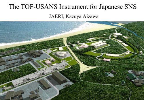
<strong>The</strong> <strong>TOF</strong>-<strong>USANS</strong> <strong>Instrument</strong> <strong>for</strong> <strong>Japanese</strong> <strong>SNS</strong><br />
JAERI, Kazuya Aizawa
J-PARC (Japan Proton Accelerator Research Complex)<br />
J<strong>SNS</strong><br />
Joint project of JAERI and KEK<br />
Joint Project between JAERI and KEK, 2001~2006( construction period)<br />
400-600 MeV Linac<br />
(Superconducting)<br />
400 MeV Linac<br />
(Normal Conducting)<br />
R&D <strong>for</strong> Nuclear<br />
Transmutation<br />
3 GeV PS<br />
(333µA, 25Hz)<br />
・1MW, Δt
Time Averaged Intensity (n/cm 2 /eV/sr)<br />
10 16<br />
10 15<br />
10 14<br />
10 13<br />
10 12<br />
10 11<br />
Intensity of J<strong>SNS</strong> moderator<br />
J<strong>SNS</strong><br />
Joint project of JAERI and KEK<br />
Time Averaged Intensity (<strong>for</strong> CM) :1/4 of ILL’s Cold source<br />
Pulse Peak Intensity (<strong>for</strong> CM) :~100 of ILL’s Cold source<br />
ILL cold (56 MW)<br />
<strong>SNS</strong> 2 MW<br />
coupled<br />
JRR-3M cold<br />
KENS (CH4)<br />
J<strong>SNS</strong> 1 MW<br />
coupled<br />
decoupled<br />
decoupled<br />
(poison)<br />
10 -5 10 -4 10 -3 10 -2 10 -1 10 0 10 1<br />
Energy (eV)<br />
Pulse Peak Intensity(n/cm 2 /s /sr/eV/pulse)<br />
10 17<br />
10 16<br />
10 15<br />
10 14<br />
10 -4<br />
10 -3<br />
Decoupled<br />
Poisoned<br />
(center)<br />
10 -2<br />
Coupled<br />
ILL cold (56 MW)<br />
10 -1<br />
Energy (eV)<br />
Hg Target<br />
Be reflector<br />
1MW 25Hz<br />
10 0<br />
10 1
Proposed J<strong>SNS</strong> low-q instruments<br />
Concept : cover wide q-range by several instruments<br />
(1) High Intensity SANS (HI-SANS)<br />
q = 0.01 - 100 nm -1<br />
pin hole collimator, magnetic, lens,<br />
converging collimator<br />
(2) High Resolution SANS (HR-SANS)<br />
merge into HI-SANS<br />
(3) Double Crystal SANS (DC-SANS)<br />
q = 0.00002 - 0.5 nm -1<br />
polymer, alloy, ceramic…
Preliminary layout of J<strong>SNS</strong><br />
Muon science facility<br />
proton<br />
Double crystal SANS (<strong>TOF</strong>-<strong>USANS</strong>)<br />
<strong>Neutron</strong> scattering facility
Feature<br />
(1) Use of harmonics (M. Agamalian et al.,SPIE’s 47 th<br />
Annual Meeting, Seattle, 2002)<br />
lower minimum q<br />
higher maximum q<br />
(2) Reduction/measurement of<br />
quasi-elastic scattering, inelastic scattering<br />
Non-dispersive<br />
symmetric Bragg case<br />
Principle of <strong>TOF</strong>-<strong>USANS</strong><br />
y = θ −θ ( B)sin2θ<br />
B −V ()E 0<br />
V( G)<br />
E ∆θn = 2 FN G ( ) ⎛ λ<br />
⎜<br />
πvcsin2θ ⎝ B n<br />
⎞<br />
Reduced angular parameter y<br />
Width of total reflection<br />
⎟<br />
⎠<br />
( )<br />
( )= 2πh2 F N G<br />
V G<br />
mvc θB : Bragg angle, E : neutron energy<br />
h = h<br />
, h : Planck's constant<br />
2π<br />
FN ( G):<br />
nuclear structure factor<br />
Extend reactor<br />
<strong>USANS</strong> q-range<br />
m : neutron mass, v c : volume of unit cell<br />
(H. Rauch and D. Petrascheck, in: <strong>Neutron</strong> Diffraction,<br />
ed., H. Dachs, Topics in Current Physics 6 (1978) 303<br />
(Springer, Heidelberg, Berlin, Göttingen))<br />
q minimum q maximum<br />
qmin,n ≈ 2π ⎛ ∆θ ⎞ n<br />
⎜ ⎟<br />
λ n⎝<br />
2 ⎠<br />
( )<br />
= 2 FN G ⎛ λ<br />
⎜<br />
vcsin2θ ⎝ B n<br />
⎞<br />
⎟<br />
⎠<br />
2<br />
G<br />
O<br />
Dispersion surf ace<br />
Maximum scattering angle of<br />
measurement<br />
∆θmax,n = ~ 2000 µrad<br />
= const<br />
λ/ 4<br />
λ/ 3<br />
λ/ 2<br />
λ<br />
qmax,n = 2π ⎛ ∆θ ⎞ max<br />
⎜<br />
λ n ⎝ 2 ⎠<br />
= π∆θ max<br />
λ<br />
n
Schematic drawing of <strong>USANS</strong><br />
insturment at J<strong>SNS</strong><br />
(1) <strong>The</strong> instrument is located No.13 port (coupled liquid H 2 moderator).<br />
In order to share the port with other instrument, pre-monochromator is used.<br />
(2) Si crystals are mounted in vacuum chamber.<br />
Because, temperature control of many samples<br />
is carried out.<br />
(3) We use thin type channel cut Si crystals.<br />
~4m<br />
Const ant t emperat ure room<br />
Goniometer in<br />
vacuum chamber<br />
1st channel cut Si,<br />
3 bounce<br />
Beam stop / monitor<br />
2nd channel cut Si,<br />
3 bounce<br />
3 He detector<br />
~3m<br />
Sheild<br />
Coupled moderator<br />
Pulsed neutron<br />
T0 chopper<br />
Pre-monochromator<br />
Slit<br />
Slit<br />
Guide tube<br />
Sample goniometer,<br />
t emperat ure cont rol<br />
Goniometer in<br />
vacuum chamber<br />
Beam st op<br />
Vibration free table<br />
7.5 m<br />
20 m<br />
other instrument
Time averaged intensity (n/cm2/sr/nm)<br />
Characteristic of No. 13 port and selected wavelength<br />
Liquid H 2 coupled moderator<br />
10 14<br />
10 13<br />
10 12<br />
10 11<br />
10 10<br />
10 9<br />
10 8<br />
Calculation codes<br />
NMTC/JAERI97<br />
MCNP4a<br />
0.001 0.01 0.1 1<br />
Wavelength (nm)<br />
Si (111)<br />
0.255 nm<br />
Intensity (n/cm2/sr/nm/pulse)<br />
10 15<br />
10 13<br />
10 11<br />
10 9<br />
0.0001 0.01 1<br />
Time (msec)<br />
0.255 nm<br />
0.0283 nm<br />
λ/9<br />
0.0283 nm Pulse shape <strong>for</strong> λ and λ/9 at 25Hz, 1MW<br />
Time averaged neutron intensity<br />
FWHM (µsec)<br />
1000<br />
100<br />
10<br />
1<br />
0.1<br />
0.001 0.01 0.1 1<br />
Wavelength (nm)<br />
FWHM of pulse shape as a function of wavelength
Width ( µrad)<br />
Calculated characteristic of <strong>TOF</strong>-<strong>USANS</strong> <strong>for</strong> J<strong>SNS</strong> -1-<br />
10<br />
1<br />
0.1<br />
0.01<br />
0.01<br />
λ/1=0.255 nm<br />
(111)<br />
(220)<br />
λ/9<br />
λ/8<br />
λ/7<br />
λ/5<br />
λ/4<br />
2 3 4 5 6 7<br />
λ (nm)<br />
λ/3<br />
λ/3<br />
0.1<br />
λ/2<br />
2 3 4<br />
Darwin width <strong>for</strong> Si (111) and Si (220) setting.<br />
Si (111)<br />
wavelength λ λ/3 λ/4 λ/5 λ/7 λ/8 λ/9<br />
notation (111) (333) (444) (555) (777) (888) (999)<br />
λ<br />
λ<br />
q min (nm -1 )<br />
10 -4<br />
10 -5<br />
2<br />
7<br />
6<br />
5<br />
4<br />
3<br />
2<br />
0.01<br />
λ/1=0.255 nm<br />
(111)<br />
(220)<br />
Si (220)<br />
wavelength λ λ/2 λ/3λ/4 λ/5 λ/6 λ/7<br />
notation (220) (440) (660) (880) (10 10 0) (12 12 0) (14 14 0)<br />
2 3 4 5 6 7<br />
λ (nm)<br />
0.1<br />
2 3 4<br />
q min <strong>for</strong> Si (111) and Si (220) setting
Si (111)<br />
Si (220)<br />
Calculated characteristic of <strong>TOF</strong>-<strong>USANS</strong> <strong>for</strong> J<strong>SNS</strong> -2-<br />
Intensity (arb. units)<br />
Intensity (arb. units)<br />
10 12<br />
10 11<br />
10 10<br />
10 9<br />
10 8<br />
10 7<br />
10 6<br />
10 5<br />
10 12<br />
10 11<br />
10 10<br />
10 9<br />
10 8<br />
10 7<br />
10 6<br />
10 5<br />
-10<br />
-10<br />
Central part of 2nd Si rocking curve<br />
-5<br />
-5<br />
0<br />
0<br />
5<br />
10<br />
θ−θΒ (µrad)<br />
5<br />
10<br />
θ−θΒ (µrad)<br />
λ/1=0.255 nm<br />
15<br />
(111)<br />
(333)<br />
(444)<br />
(555)<br />
(777)<br />
(888)<br />
(999)<br />
20<br />
λ/1=0.255 nm<br />
15<br />
(220)<br />
(440)<br />
(660)<br />
(880)<br />
(10 10 0)<br />
(12 12 0)<br />
(14 14 0)<br />
20<br />
25<br />
25<br />
Intensity (arb. units)<br />
Intensity (arb. units)<br />
10 12<br />
10 11<br />
10 10<br />
10 9<br />
10 8<br />
10 7<br />
10 6<br />
10 5<br />
10 12<br />
10 11<br />
10 10<br />
10 9<br />
10 8<br />
10 7<br />
10 6<br />
10 5<br />
Central part of 2nd Si rocking curve in q-scale<br />
10 -6<br />
10 -6<br />
10 -5<br />
10 -5<br />
10 -4<br />
q (nm -1 )<br />
10 -4<br />
q (nm -1 )<br />
λ/1=0.255 nm<br />
10 -3<br />
10 -3<br />
(111)<br />
(333)<br />
(444)<br />
(555)<br />
(777)<br />
(888)<br />
(999)<br />
λ/1=0.255 nm<br />
(220)<br />
(440)<br />
(660)<br />
(880)<br />
(10 10 0)<br />
(12 12 0)<br />
(14 14 0)<br />
We assumed that the reflectivity of the pre-monochrometer to the neutron which diffracts dynamically on Si crystals was equal.<br />
10 -2<br />
10 -2
Intensity (arb. units)<br />
10 13<br />
10 11<br />
10 9<br />
10 7<br />
10 5<br />
Measurement diagram<br />
~ -2000 µrad step scan<br />
~2000 µrad<br />
first frame<br />
elastic scattering<br />
(444)<br />
(555)<br />
(777)<br />
(888)<br />
(999)<br />
-100 -50 0 50 100<br />
θ−θ Β (µrad)<br />
(333)<br />
(111)<br />
fine step<br />
inelastic scattering<br />
Central part of step scan <strong>for</strong> 2nd Si rocking curve<br />
1<br />
larger step<br />
Flight distance (m)<br />
20<br />
15<br />
10<br />
5<br />
0<br />
0<br />
40<br />
<strong>TOF</strong> (msec)<br />
10<br />
10<br />
20<br />
<strong>TOF</strong> (msec)<br />
25 Hz<br />
λ/1=0.255 nm<br />
30<br />
(111)<br />
(333)<br />
(444)<br />
(555)<br />
(777)<br />
(888)<br />
(999)<br />
Flight distance - <strong>TOF</strong> diagram<br />
detector<br />
sample<br />
T0 chopper<br />
moderator<br />
40
10 -5<br />
pulse<br />
Per<strong>for</strong>mance of <strong>TOF</strong>-<strong>USANS</strong><br />
case of Si (111) setting<br />
10 -4<br />
reactor<br />
10 -3<br />
q (nm -1 )<br />
10 -2<br />
λ=0.255nm<br />
(111)<br />
10 -1<br />
(333)<br />
(999)<br />
(555)<br />
(444)<br />
(888)<br />
(777)<br />
λ/1=0.255nm<br />
10 0<br />
Calculated q-range of <strong>TOF</strong>-<strong>USANS</strong> and reactor-<strong>USANS</strong><br />
<strong>TOF</strong>-<strong>USANS</strong><br />
q =~ 2×10 −5 − 0.5 nm −1<br />
Gain ~<br />
( )<br />
m Ip n<br />
∑ =~12,<br />
n=1<br />
I r<br />
n =1,3,4,5,7,8,9<br />
Ip n<br />
I r<br />
() : neutron flux <strong>for</strong> nth order reflection<br />
at pulsed source<br />
: neutron flux at reactor source<br />
Reactor-<strong>USANS</strong><br />
q =~ 2×10 −4 − 0.05 nm −1
Intensity (cps)<br />
1000<br />
100<br />
10<br />
0.001<br />
1<br />
0.1<br />
0.01<br />
10 -5<br />
Per<strong>for</strong>mance of Reactor <strong>USANS</strong> at JRR-3<br />
B.G level<br />
10 -4<br />
10 -3<br />
q (nm -1 )<br />
λ = 0.2 nm<br />
Rocking curve<br />
Ewald curve<br />
10 -2<br />
10 -1<br />
Rocking curve of 2nd channel cut Si-crystal of thin type<br />
Thin type channel cut Si<br />
effective <strong>for</strong> background reduction<br />
S/N ratio : 2 ~ 2.6 ×10 5<br />
neut ron<br />
Thick type<br />
0.25 nm<br />
10 110<br />
10<br />
5 bounce<br />
Thick - thin type<br />
Cd<br />
130<br />
<br />
Cd<br />
2 15 2<br />
19<br />
unit mm
Moderator<br />
Repetition<br />
T0 chopper<br />
L1<br />
(L2)<br />
Pre-monochromator<br />
Crystal<br />
Temperature control<br />
Table<br />
Detector<br />
DC-SANS parameters<br />
Coupled liquid H 2<br />
25 Hz<br />
~7.5m<br />
~21 m<br />
(~1.0m)<br />
Bent PG/Bent Si<br />
Si 111, Si 220,triple-triple bounce<br />
Constant temp. room + chamber<br />
Vibration free table<br />
3 He proportional counter


