4 Construction - nptel - Indian Institute of Technology Madras
4 Construction - nptel - Indian Institute of Technology Madras
4 Construction - nptel - Indian Institute of Technology Madras

You also want an ePaper? Increase the reach of your titles
YUMPU automatically turns print PDFs into web optimized ePapers that Google loves.
Electrical Machines II Pr<strong>of</strong>. Krishna Vasudevan, Pr<strong>of</strong>. G. Sridhara Rao, Pr<strong>of</strong>. P. Sasidhara Rao<br />
4 <strong>Construction</strong><br />
In actual practice, the three coils form three windings distributed over several slots. These<br />
windings may be connected in star or delta and three terminations are brought out. These<br />
are conventional three phase windings which are discussed in greater detail in the chapters<br />
on alternators. Such windings are present n the stator as well as rotor. A photograph <strong>of</strong><br />
<strong>Indian</strong> <strong>Institute</strong> <strong>of</strong> <strong>Technology</strong> <strong>Madras</strong><br />
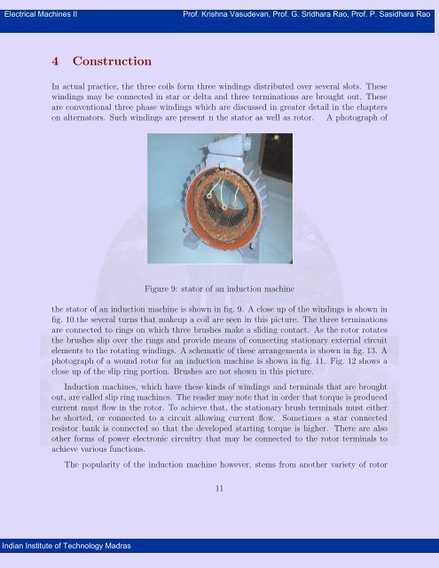
Figure 9: stator <strong>of</strong> an induction machine<br />
the stator <strong>of</strong> an induction machine is shown in fig. 9. A close up <strong>of</strong> the windings is shown in<br />
fig. 10.the several turns that makeup a coil are seen in this picture. The three terminations<br />
are connected to rings on which three brushes make a sliding contact. As the rotor rotates<br />
the brushes slip over the rings and provide means <strong>of</strong> connecting stationary external circuit<br />
elements to the rotating windings. A schematic <strong>of</strong> these arrangements is shown in fig. 13. A<br />
photograph <strong>of</strong> a wound rotor for an induction machine is shown in fig. 11. Fig. 12 shows a<br />
close up <strong>of</strong> the slip ring portion. Brushes are not shown in this picture.<br />
Induction machines, which have these kinds <strong>of</strong> windings and terminals that are brought<br />
out, are called slip ring machines. The reader may note that in order that torque is produced<br />
current must flow in the rotor. To achieve that, the stationary brush terminals must either<br />
be shorted, or connected to a circuit allowing current flow. Sometimes a star connected<br />
resistor bank is connected so that the developed starting torque is higher. There are also<br />
other forms <strong>of</strong> power electronic circuitry that may be connected to the rotor terminals to<br />
achieve various functions.<br />
The popularity <strong>of</strong> the induction machine however, stems from another variety <strong>of</strong> rotor<br />
11
Electrical Machines II Pr<strong>of</strong>. Krishna Vasudevan, Pr<strong>of</strong>. G. Sridhara Rao, Pr<strong>of</strong>. P. Sasidhara Rao<br />
<strong>Indian</strong> <strong>Institute</strong> <strong>of</strong> <strong>Technology</strong> <strong>Madras</strong><br />
Figure 10: Coils in the stator<br />
Figure 11: A wound rotor with slip rings<br />
12
Electrical Machines II Pr<strong>of</strong>. Krishna Vasudevan, Pr<strong>of</strong>. G. Sridhara Rao, Pr<strong>of</strong>. P. Sasidhara Rao<br />
Winding<br />
on rotor<br />
<strong>Indian</strong> <strong>Institute</strong> <strong>of</strong> <strong>Technology</strong> <strong>Madras</strong><br />
Figure 12: slip rings<br />
v<br />
Sliding<br />
Contact<br />
Slip rings(fixed to shaft)<br />
Brushes(stationary)<br />
Stationary terminals<br />
Rotor shaft<br />
Figure 13: Slip rings and brushes in induction machines — a schematic<br />
13
Electrical Machines II Pr<strong>of</strong>. Krishna Vasudevan, Pr<strong>of</strong>. G. Sridhara Rao, Pr<strong>of</strong>. P. Sasidhara Rao<br />
that is used. This rotor has slots into which copper or aluminium bars are inserted. These<br />
bars are then shorted by rings that are brazed on to each <strong>of</strong> the rotor ends. Figure 14 shows<br />
a simple schematic.<br />
<strong>Indian</strong> <strong>Institute</strong> <strong>of</strong> <strong>Technology</strong> <strong>Madras</strong><br />
Figure 14: Squirrel cage rotor — a schematic<br />
Such a rotor is called squirrel cage rotor. This rotor behaves like a short-circuited winding<br />
and hence the machine is able to perform electromechanical energy conversion. This type<br />
<strong>of</strong> rotor is easy to manufacture, has no sliding contacts and is very robust. It is this feature<br />
that makes induction machine suitable for use even in hazardous environments and reliable<br />
operation is achieved. The disadvantage <strong>of</strong> this type <strong>of</strong> rotor is that the motor behavior<br />
cannot be altered by connecting anything to the rotor — there are no rotor terminals.<br />
Fig. 15 shows a photograph <strong>of</strong> a squirrel cage rotor. The rotor also has a fan attached<br />
to it. This is for cooling purposes. The bars ( white lines on the surface) are embedded in<br />
the rotor iron which forms the magnetic circuit. The white lines correspond to the visible<br />
portion <strong>of</strong> the rotor bar.<br />
Sometimes two rotor bars are used per slot to achieve some degree <strong>of</strong> variability in the<br />
starting and running performances. It is to make use <strong>of</strong> the fact that while high rotor<br />
14
Electrical Machines II Pr<strong>of</strong>. Krishna Vasudevan, Pr<strong>of</strong>. G. Sridhara Rao, Pr<strong>of</strong>. P. Sasidhara Rao<br />
<strong>Indian</strong> <strong>Institute</strong> <strong>of</strong> <strong>Technology</strong> <strong>Madras</strong><br />
Figure 15: squirrel cage rotor<br />
resistance is desirable from the point <strong>of</strong> view <strong>of</strong> starting torque, low rotor resistance is<br />
desirable from efficiency considerations while the machine is running. Such rotors are called<br />
double cage rotors or deep-bar rotors.<br />
To summarize the salient features discussed so far,<br />
1. The stator <strong>of</strong> the 3 - phase induction machine consists <strong>of</strong> normal distributed AC windings.<br />
2. Balanced three phase voltages impressed on the stator, cause balanced three phase<br />
currents to flow in the stator.<br />
3. These stator currents cause a rotating flux pattern (the pattern is a flux distribution<br />
which is sinusoidal with respect to the space angle) in the air gap.<br />
4. The rotating flux pattern causes three phase induced e.m.f.s in rotor windings (again<br />
normal ac windings). These windings, if shorted, carry three phase-balanced currents.<br />
Torque is produced as a result <strong>of</strong> interaction <strong>of</strong> the currents and the air gap flux.<br />
5. The rotor may also take the form <strong>of</strong> a squirrel cage arrangement, which behaves in a<br />
manner similar to the short-circuited three phase windings.<br />
15