Manual Drivetrains and Axles Fourth Edition
Manual Drivetrains and Axles Fourth Edition
Manual Drivetrains and Axles Fourth Edition

You also want an ePaper? Increase the reach of your titles
YUMPU automatically turns print PDFs into web optimized ePapers that Google loves.
OBJECTIVES:<br />
After studying this presentation, the reader<br />
should be able to:<br />
Prepare for the ASE Automatic<br />
Transmission/Transaxle (A2) certification test<br />
content area “A” (General Transmission/Transaxle<br />
Diagnosis)<br />
Explain how a torque converter can transmit <strong>and</strong><br />
multiply engine torque<br />
Describe how a planetary gear set can be used for<br />
gear reduction <strong>and</strong> reverse<br />
Continued
OBJECTIVES:<br />
After studying this presentation, the reader<br />
should be able to:<br />
Explain how automatic transmission fluid is<br />
circulated through the system <strong>and</strong> how it is cooled
KEY TERMS:<br />
compound planetary gear set • coupling phase<br />
flexplate<br />
impeller • input member<br />
lapelleties gear set • lube oil<br />
output member<br />
pump<br />
ravigneaux gear set • reaction member<br />
Continued
KEY TERMS:<br />
simpson gear set • stall speed • stator<br />
torque converter clutch (TCC) • torque multiplication<br />
phase • turbine
Automatic transmissions were first used on a large scale<br />
in the late 1940s, <strong>and</strong> now about 85% of the vehicles in<br />
North America are so equipped.<br />
Unlike manual transmissions, most automatic<br />
transmissions do not actually “shift gears” but apply<br />
clutches (or b<strong>and</strong>s) to hold various sections of two or<br />
more planetary gear sets.<br />
The torque converter is attached between the engine <strong>and</strong><br />
the transmission/ transaxle <strong>and</strong> transmits <strong>and</strong><br />
multiplies engine torque.
TORQUE CONVERTERS<br />
The impeller, also known as the pump, is the driving member <strong>and</strong><br />
rotates with the engine. The impeller vanes pick up fluid in the converter<br />
housing <strong>and</strong> direct it toward the turbine.<br />
Fluid flow drives the turbine, <strong>and</strong> when the flow between the impeller<br />
<strong>and</strong> turbine is adequate, the turbine rotates <strong>and</strong> turns the transmission<br />
input shaft. A torque converter contains the stator, or reactor, a reaction<br />
member mounted on a one-way clutch.<br />
The vanes used in each of the three elements of a torque converter are<br />
curved to increase the diversion angle of the fluid. This also increases<br />
the force exerted by the fluid <strong>and</strong> improves the hydraulic advantage. See<br />
Figure 100–1.<br />
Continued
Figure 100–1 A cross-sectional view of a Chrysler Power Flight 2-speed automatic transmission used in the 1950s. Most of<br />
the heat generated in an automatic transmission is created in the torque converter. This air-cooled unit has a vent to allow<br />
hot air to escape.<br />
Continued
The outlet side of the impeller vanes accelerates the fluid as it<br />
leaves the impeller to increase torque transfer to the turbine.<br />
See Figure 100–2.<br />
The inlet side of the turbine vanes absorb shock <strong>and</strong> limit power<br />
loss that occurs when flow between the impeller <strong>and</strong> turbine<br />
suddenly changes. The curve of the stator vanes is opposite to the<br />
curve of the impeller <strong>and</strong> turbine vanes.<br />
See Figure 100–3.<br />
Since the stator is located between the impeller <strong>and</strong> turbine, it adds<br />
to the original impeller flow <strong>and</strong> multiplies the force delivered to<br />
the turbine. See Figure 100–4.<br />
Continued
Figure 100–2 Fluid flow within a torque converter. The stator redirects the fluid that is thrown out by the turbine, thereby<br />
improving efficiency.<br />
Continued
Figure 100–3 Fluid pumped into the<br />
turbine by the impeller not only creates<br />
rotary fluid flow but also vortex flow that<br />
increases the efficiency of the torque<br />
converter.<br />
Continued
Figure 100–4 The vane curvature of each element in a<br />
torque converter helps maintain efficient fluid flow<br />
Torque converters are single-piece,<br />
welded assemblies that cannot be<br />
disassembled or repaired easily.<br />
Although they can be rebuilt using<br />
specialized equipment, most shops<br />
simply replace welded converters as<br />
a unit if they fail.<br />
Continued
Torque Converter Attachments The torque converter normally<br />
attaches to the engine through a flexplate that mounts on the<br />
crankshaft flange of the engine.<br />
The flexplate replaces the heavy flywheel used with a manual<br />
transmission. An important function of a flywheel is to smooth out<br />
engine pulsations <strong>and</strong> dampen vibrations.<br />
An automatic transmission does not require a conventional<br />
flywheel because the fluid in the torque converter provides<br />
enough mass to dampen engine vibrations.<br />
See Figure 100–5.<br />
Continued
Figure 100–5<br />
The torque converter bolts to the flexplate,<br />
which is attached to the crankshaft <strong>and</strong><br />
rotates at engine speed. The hub of the<br />
converter drives the oil pump directly on<br />
most rear wheel-drive transmissions.<br />
An external ring gear<br />
generally attaches to the<br />
outer rim of the flexplate.<br />
This ring gear engages the<br />
starter motor pinion gear<br />
to turn the engine during<br />
starting.
NOTE: On some older applications, such as the Ford C4 <strong>and</strong> Chrysler<br />
Torqueflite, the ring gear may be welded to the outside of the torque<br />
converter cover.<br />
To ensure the pump will deliver fluid to the transmission whenever the engine<br />
turns, an integral hub is located on the converter housing <strong>and</strong> directly engages<br />
the pump.<br />
Oil pump drive shafts generally pass through the converter inside<br />
a hollow input or transfer shaft <strong>and</strong> internally connect to the converter housing<br />
by splines.<br />
Most rear-wheel-drive transmissions use an inline method to drive the converter<br />
<strong>and</strong> provide a direct mechanical connection between the turbine <strong>and</strong> the<br />
transmission input shaft.<br />
See Figure 100–6.
Figure 100–6 The inner oil pump gear is keyed to the hub of the torque converter, which drives the pump. Notice that the<br />
hub does not engage the full depth of the gear. This is the major reason why the torque converter must be fully installed.<br />
Failure to fully engage the oil pump gear can cause serious damage to both the pump <strong>and</strong> the torque converter.<br />
Continued
In a typical design, splines on the turbine connect it to the<br />
transmission input shaft <strong>and</strong> the stator hub mounts on a one-way<br />
overrunning clutch.<br />
The one-way clutch mounts on splines to a stationary extension<br />
of the oil pump called the stator support, or reaction shaft. The<br />
converter drive hub at the rear of the torque converter housing<br />
passes over the stator support <strong>and</strong> through the front oil seal to<br />
drive the oil pump.<br />
See Figure 100–7.<br />
Continued
Figure 100–7<br />
The transmission input shaft connects<br />
directly to the turbine through splines<br />
in most rear-wheel-drive<br />
transmissions.<br />
Continued
Many transaxles, <strong>and</strong> a few rear-wheel-drive transmissions, use an<br />
offset drive arrangement to conserve space.<br />
An offset drive design generally uses a drive chain to provide the<br />
mechanical connection between the turbine <strong>and</strong> the input shaft.<br />
The oil pump may be driven directly by the converter housing or<br />
by a separate drive shaft.<br />
See Figure 100–8.<br />
Continued
Figure 100–8 On a transaxle, the turbine drives the input shaft through a drive chain assembly.<br />
Continued
Torque Converter Operation Fluid sent to the torque converter<br />
from the transmission oil pump is picked up by the rotating vanes<br />
of the impeller <strong>and</strong> transferred to the turbine vanes through rotary<br />
<strong>and</strong> vortex flow paths.<br />
Torque Multiplication Phase Fluid leaving the turbine vanes<br />
strikes the concave, or front side, of the stator vanes during the<br />
torque multiplication phase.<br />
The force of the fluid from the stator adds to the force of the fluid<br />
flowing from the impeller to increase the overall torque being<br />
transferred from the impeller to the turbine.<br />
Torque multiplication occurs whenever the vortex flow makes a<br />
full cycle from impeller to turbine, then through the stator <strong>and</strong> back<br />
to the impeller. See Figure 100–9.<br />
Continued
Figure 100–9 Torque multiplication occurs when fluid leaving<br />
the turbine strikes the front of the stator vanes <strong>and</strong> is<br />
redirected back to the impeller.<br />
A torque converter multiplies<br />
torque in relation to speed ratio.<br />
At low ratios, the impeller is<br />
turning much faster than the<br />
turbine, so vortex flow is high<br />
<strong>and</strong> torque multiplication occurs.<br />
As the speed ratio approaches<br />
90%, torque multiplication<br />
becomes minimal <strong>and</strong> a torque<br />
converter functions like a fluid<br />
coupling.<br />
Continued
The stator redirects fluid flow because it remains stationary during<br />
the torque multiplication phase. The stator hub mounts on a oneway<br />
clutch, freewheeling in a clockwise direction, but locking<br />
when driven in a counterclockwise direction.<br />
Figure 100–10 A stator contains a one-way roller<br />
clutch, which locks it from rotating in one direction<br />
<strong>and</strong> allows it to rotate freely in the opposite direction.<br />
When fluid from the turbine strikes the concave face of the stator<br />
vanes, it tries to drive the stator counterclockwise. By locking the<br />
stator it can redirect the fluid back to the impeller. Continued
Coupling Phase When the speed ratio is 90% or more, fluid flow in the<br />
toque converter is mostly rotary flow <strong>and</strong> the angle of flow from turbine<br />
to stator increases.<br />
Fluid eventually strikes the convex side, or backside, of the stator vanes<br />
rather than the concave. As the force of fluid striking the backside<br />
becomes great enough to drive the stator clockwise, the one-way clutch<br />
overruns.<br />
With the clutch overrunning the turbine, impeller, <strong>and</strong> stator, all rotate in<br />
the same direction <strong>and</strong> at approximately the same speed. This is called<br />
the coupling phase.<br />
The stator unlocks <strong>and</strong> freewheels once the angle of fluid flow changes<br />
enough to strike the opposite side of the stator vanes <strong>and</strong> rotate the stator<br />
clockwise.<br />
Continued
Torque multiplication drops as the torque converter approaches<br />
the coupling phase because the stator no longer redirects fluid to<br />
increase the flow from impeller to turbine.<br />
When the torque converter reaches coupling speed, the turbine is<br />
traveling at nearly the same speed as the impeller, rotary flow is<br />
much greater than vortex flow, <strong>and</strong> the torque converter simply<br />
transmits torque like a fluid coupling.<br />
Continued
Stall Speed During converter stall, the impeller rotates but the<br />
turbine does not. This occurs just before the drive wheels of a<br />
vehicle begin to move.<br />
The greatest amount of stall occurs when the engine drives the<br />
impeller at the maximum speed possible without moving the<br />
turbine. The engine speed at which this occurs is called the torque<br />
converter stall speed. When the impeller rotates but the turbine<br />
does not, the speed ratio is zero.<br />
This is the lowest possible speed ratio <strong>and</strong> the greatest possible<br />
torque multiplication. Most modern torque converters multiply<br />
torque in the range of 2:1 to 2.5:1 at the stall speed.<br />
Continued
Torque Converter Diameter The outside diameter of a torque<br />
converter <strong>and</strong> the angle of its stator blades determines the stall<br />
speed of the converter.<br />
When both a small <strong>and</strong> large diameter converter share the same<br />
stator blade angle <strong>and</strong> turn at the same speed, the smaller converter<br />
creates less centrifugal force to move the fluid inside.<br />
As a result, the small diameter converter has a higher stall speed,<br />
multiplies torque at higher engine speeds, <strong>and</strong> will not couple until<br />
the engine reaches high speeds.<br />
In comparison, the large diameter converter has a lower stall speed,<br />
multiplies torque at lower engine speeds, <strong>and</strong> also couples at a<br />
lower engine speed.<br />
Continued
Vehicle manufacturers select torque converters to match the power<br />
train requirements <strong>and</strong> operating dem<strong>and</strong>s of each application.<br />
A vehicle with a large engine that produces a lot of torque at low<br />
RPM will often use a torque converter that couples at low speeds<br />
for greater fuel economy.<br />
Vehicles with smaller engines that produce less torque at low RPM<br />
will use a torque converter that allows the engine to operate higher<br />
in its torque curve, where more power is available.<br />
High-performance vehicles with automatic transmissions use small<br />
diameter converters for the same reason.<br />
Continued
Lockup Torque Converter Even the most efficient torque converters<br />
slip 3% to 6% during operation. This is because the fluid that transmits<br />
torque exhibits a type of slippage known as fluid shear. Fluid shear<br />
creates friction heat, but performs no work when the different layers of<br />
fluid slide past each other.<br />
Eliminating torque converter slippage can improve fuel economy<br />
approximately 4% to 5% during freeway cruising. With increased<br />
emphasis on fuel economy for late-model vehicles, this became<br />
an important goal for automotive engineers.<br />
Lockup torque converters reduce slippage by using a torque converter<br />
clutch (TCC) to lock the impeller to the turbine. Similar to a clutch for a<br />
manual transmission, a TCC uses a friction disc operated by a hydraulic<br />
piston to mechanically<br />
couple the turbine to the impeller. See Figure 100–11<br />
Continued
Figure 100–11 An exp<strong>and</strong>ed view of a typical General Motors torque converter clutch (TCC).<br />
Continued
Converter Clutch Control The first hydraulic lockup converters were<br />
controlled entirely by hydraulic pressure <strong>and</strong> spool valves in the<br />
transmission valve body.<br />
Some later designs added simple electric switches <strong>and</strong> solenoids to<br />
control pressure to the converter clutch. Late-model hydraulic TCCs use<br />
an electronic control system to regulate the timing <strong>and</strong> application of the<br />
clutch.<br />
Early hydraulic converter clutches will engage only in high gear because<br />
lockup in the lower gears reduces the torque multiplication needed for<br />
acceleration. Lockup may also be limited to specific vehicle speeds or<br />
operating conditions. For most vehicles, lockup can occur at speeds over<br />
25 to 30 mph (40 to 48 km/h) after the transmission upshifts into high<br />
gear.<br />
Continued
Once lockup occurs, the clutch may disengage automatically during<br />
certain operating conditions such as part- or full-throttle downshift. At<br />
these times, the increased acceleration requirements generally override<br />
the need for better fuel economy.<br />
The more sophisticated electronic control systems can lock <strong>and</strong> unlock a<br />
converter clutch hundreds of times per minute to meet the vehicle<br />
dem<strong>and</strong>s of the moment.<br />
Some recent systems also allow partial lockup of the torque converter.<br />
Traditional lockup torque converters operate either locked or unlocked.<br />
Partial lockup converters allow a regulated amount of slippage at the<br />
clutch.<br />
See Figure 100–12 .<br />
Continued
Figure 100–12 The type of torque converter clutch control determines the type of friction material that is used on a torque<br />
converter clutch. A paper friction material is usually used on clutches that are turned on or off, whereas Kevlar® or carbon<br />
fiber friction materials are used where the clutch is pulse-width modulated.<br />
Continued<br />
CARBON FIBER<br />
KEVLAR ®<br />
PAPER
The summary of torque converter operation is as follows:<br />
Engine speed is low with the vehicle in gear <strong>and</strong> stopped. At<br />
low engine speeds, automatic transmission fluid does not exert<br />
enough force on to permit the vehicle to move at a creep.<br />
Engine speed increases <strong>and</strong> vehicle speed starts to increase<br />
As more engine torque is applied to the torque converter, the<br />
torque is transmitted through the movement of the fluid to the<br />
turbine. The stator is locked (prevented from moving) <strong>and</strong><br />
redirects the fluid flow back against the turbine. The redirection<br />
of the fluid back to the turbine creates a torque on the turbine<br />
that is greater than the engine torque.<br />
This is called torque multiplication. Most torque converters are<br />
capable of doubling the applied engine torque due to redirection<br />
of the fluid by the stator.<br />
Continued
NOTE: That the torque converter can double torque to the transmission is<br />
the major advantage of using an automatic transmission. A clutch used in a<br />
manual transmission/transaxle can only transmit engine torque.<br />
Engine speed is steady <strong>and</strong> vehicle speed is steady When the speed of both<br />
the impeller <strong>and</strong> the turbine reach about the same speed (85% to 90%), the<br />
one-way clutch in the stator unlocks <strong>and</strong> the stator is free to rotate. This is<br />
called the coupling point.<br />
Vehicle is accelerated rapidly During periods of rapid acceleration, the<br />
engine speed <strong>and</strong> therefore the impeller speed are a great deal faster than the<br />
turbine speed. The greatest amount of torque multiplication occurs when the<br />
turbine is stopped <strong>and</strong> the impeller is turning as fast as the engine will turn it.<br />
This speed is called the stall speed.<br />
Continued
Vehicle speed is above 35 mph (55 km/h) <strong>and</strong> steady<br />
To improve fuel economy, the impeller <strong>and</strong> the turbine are<br />
mechanically connected by a torque converter clutch (TCC), also<br />
known as a lockup torque converter.<br />
Except for rare cases, the torque converter clutch is applied by the<br />
vehicle computer. The computer senses vehicle speed (VS), engine<br />
load (MAP), <strong>and</strong> throttle position (TP) <strong>and</strong> applies the torque<br />
converter clutch.<br />
This lockup can occur in second, third, or fourth (overdrive) gear if<br />
the conditions are right. When the torque converter clutch engages,<br />
the engine RPM usually drops by 150 to 250 RPM.<br />
See Figure 100–13.<br />
Continued
Figure 100–13 A cross-sectional view of a computercontrolled<br />
(modulated) torque converter clutch. The<br />
vehicle computer is capable of pulsing the solenoid<br />
that controls the fluid flow on <strong>and</strong> off to apply the<br />
torque converter clutch.<br />
Reduction in engine speed<br />
<strong>and</strong> the elimination of the<br />
normal slippage in the torque<br />
converter improves fuel<br />
economy.<br />
The torque converter clutch<br />
is released during rapid<br />
acceleration for maximum<br />
torque multiplication through<br />
the torque converter for best<br />
acceleration.<br />
Continued
NOTE: The application of the torque converter clutch feels like a normal<br />
shift to most drivers. Therefore, a three-speed automatic transaxle will feel<br />
to many drivers as “shifting” three times (1-2, 2-3, <strong>and</strong> TCC engagement).<br />
CAUTION: Using a nonstock torque converter is likely to increase<br />
exhaust emissions <strong>and</strong> decrease fuel economy.
Use a Smaller Diameter Torque Converter for Improved<br />
Performance<br />
A smaller-than-stock-diameter torque converter will not be capable of<br />
absorbing as much torque as a larger (stock) torque converter. As a result, the<br />
stall speed is increased.<br />
Because an engine develops more torque with increased speed (up to a<br />
point), the smaller torque converter will allow the engine to increase to a<br />
higher speed <strong>and</strong> create more torque to the transmission than would be<br />
capable with the stock torque converter.<br />
This is especially helpful for modified engines because an engine having a<br />
camshaft with increased lift <strong>and</strong> duration usually lacks low RPM torque. By<br />
using a smaller torque converter, the stall speed is increased to better match<br />
the engine torque.
Automatic Transmission Fluid Cooler The torque converter generates a lot of heat due to the<br />
slippage <strong>and</strong> torque multiplication that occurs inside. The greatest amount is under a heavy<br />
load with the torque converter clutch is disengaged.<br />
The transmission fluid (ATF) can reach high temperatures (over 250°F [120°C]) very quickly.<br />
This is the reason an automatic transmission fluid cooler is used. Most vehicles use a small<br />
section of the engine radiator to cool the ATF.<br />
The ATF is pumped from the torque converter (greatest source of heat) to the cooler. The ATF<br />
flows through the cooler <strong>and</strong> returns to the transmission/transaxle to passages that lubricate the<br />
bearings <strong>and</strong> bushings of the unit. This returned fluid is called lube oil.<br />
See Figures 100–14 <strong>and</strong> 100–15.<br />
Continued
Figure 100–14 Automatic transmission fluid is routed from the torque converter, where most of the heat in an automatic<br />
transmission is generated, to the radiator, where it is cooled. The cooled fluid then returns to the transmission/transaxle to<br />
lubricate the bearings <strong>and</strong> bushings.<br />
Continued
Figure 100–15 A cutaway section of a typical radiator showing the automatic transmission fluid cooler. The heat from the<br />
automatic transmission fluid is released to the engine coolant. The engine coolant also warms the automatic transmission<br />
fluid after a cold start.<br />
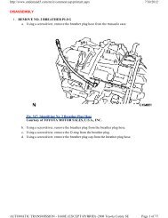
CAUTION: Because the lube oil uses the ATF flowing from the cooler,<br />
if there is a blockage in the cooler, the transmission/transaxle may not have<br />
enough fluid to properly cool or lubricate the bearings <strong>and</strong> bushings inside<br />
the unit, leading to wear <strong>and</strong> eventually premature failure.<br />
Continued
PLANETARY GEAR SETS<br />
In a manual transmission, different gear ratios are obtained by sliding the gears<br />
into mesh. Torque flow must be momentarily interrupted (accomplished by<br />
using a clutch) before the gears are shifted.<br />
With an automatic transmission there is no driver-operated clutch, so gear shifts<br />
are not made by sliding gears into mesh.<br />
Automatic transmissions use a planetary gear set system that does not require<br />
manual gear shifting or an interruption of torque flow to change gear ratios.<br />
Continued
A simple planetary gear set consists of three primary components:<br />
Sun gear<br />
Planet carrier assembly<br />
Ring gear<br />
As discussed in the last chapter, the sun gear gets its name from<br />
its position at the center of the gear set. The planet carrier<br />
assembly holds the pinion gears, also known as planet<br />
gears, which revolve around the sun gear.<br />
The outermost member of the gear set is the ring gear, which<br />
is the internal type with the teeth inside. The pinion gears are<br />
in simultaneous mesh with both the sun <strong>and</strong> ring gear.<br />
Continued
The pinion gears are free to rotate on pins that are part of the carrier, <strong>and</strong><br />
the entire assembly rotates to direct torque flow.<br />
The simple planetary gear set as seen in Figure 100–16 has only two<br />
planet pinions, but most transmission gear sets use three or four.<br />
The pinions are fully meshed with both the sun gear <strong>and</strong> internal ring<br />
gear at all times.<br />
The planetary gears never disengage to change gear ratios; torque is<br />
simply redirected.<br />
Continued
All gears in a planetary gear set<br />
are in constant mesh.<br />
The torque flow through a<br />
planetary gear set, both input<br />
<strong>and</strong> output, occurs along a<br />
single axis.<br />
The internal ring gear is<br />
sometimes called an annulus<br />
gear or a ring gear<br />
The planet pinion gears are<br />
often called planet gears or<br />
pinion gears.<br />
The planet carrier assembly is<br />
referred to as the “carrier.”<br />
Figure 100–16 The three members of a simple planetary<br />
gear set are the sun gear, internal ring gear, <strong>and</strong> planet<br />
carrier assembly.<br />
Continued
Planetary Gear Set Torque Flow In any planetary gear set, each gear always meshes with<br />
several other gears.<br />
Driving one gear will drive all of the other gears as well. This allows the gear set to provide<br />
different gear ratios; depending upon how torque is distributed through the assembly. To<br />
transmit torque through a planetary gear set, a drive member rotates while a second member is<br />
held, which causes a third member to be driven.<br />
Each member of a planetary gear set can play any one of these three roles to transmit torque.<br />
The various combinations of drive, held, <strong>and</strong> driven members result in the number of gear<br />
ratios available. Certain combinations of drive, hold, <strong>and</strong> driven can change the direction of<br />
rotation as well.<br />
See Figure 100–17.<br />
Continued
Figure 100–17 To transmit torque<br />
through a planetary gear set, one<br />
(input) member drives, another<br />
(reaction) member is held, <strong>and</strong> the<br />
third (output) member is driven.<br />
Continued
Torque flows through a planetary gear set in several steps to get from the<br />
drive action of the first member to the driven action of the last member.<br />
The terms “drive” <strong>and</strong> “driven” simply describe how any two gears work<br />
together. When three or more gears are involved, the second gear is a<br />
driven gear in relation to the first, but a drive gear in relation to the third.<br />
For this reason, the drive member of a planetary gear set is known as the<br />
input member, the held member is the reaction member, <strong>and</strong> the driven<br />
member is the output member.<br />
See Figure 100–18 for the possible gear ratios <strong>and</strong> how they are<br />
achieved.<br />
Continued
Figure 100–18 Different modes of transferring torque through a planetary gear set.
Simple Planetary Gear Set Systems A simple planetary gear set system consists of one sun<br />
gear, carrier, <strong>and</strong> ring gear. A single planetary gear set can provide all of the necessary gear<br />
ratios for a basic automatic transmission.<br />
Using a simple planetary gear set along with a brake b<strong>and</strong> <strong>and</strong> multiple disc clutch as apply<br />
devices, you can design a two-speed automatic transmission. The transmission provides neutral<br />
<strong>and</strong> reverse gearing, <strong>and</strong> performs “low to drive” gear changes<br />
without any input from the driver.<br />
The simple planetary gear set remains the foundation upon which the compound planetary gear<br />
sets used in modern transmissions are built. A simple planetary gear set is often used together<br />
with a compound planetary gear set to provide additional overdrive gearing.<br />
Continued
SIMPSON GEAR SET<br />
A compound planetary gear set system is a configuration that contains more than just the<br />
three basic members of a simple planetary system.<br />
Compound planetary gear sets are capable of providing various combinations of gear<br />
reduction, direct drive, neutral, reverse, <strong>and</strong> overdrive.<br />
The most popular compound planetary design is the Simpson gear set. Named for its<br />
inventor, the Simpson gear set consists<br />
of two simple planetary gear sets that share a common sun gear.<br />
See Figure 100–19.<br />
Continued
This combination is capable<br />
of providing three forward<br />
gears, as well as neutral <strong>and</strong><br />
reverse.<br />
Operation, construction,<br />
<strong>and</strong> methods of obtaining<br />
various gear ratios with a<br />
simple planetary gear set<br />
also apply to the Simpson<br />
gear set.<br />
The main difference is the<br />
number of gear ratios.<br />
Continued<br />
Figure 100–19 A Simpson planetary gear set is composed of two<br />
ring gears <strong>and</strong> two planet carrier assemblies that share a common<br />
sun gear.
RAVIGNEAUX GEAR SET<br />
Another popular compound planetary design is the Ravigneaux gear set. The Ravigneaux system has two<br />
sun gears; two sets, one longer than the other, of planet pinions supported in one carrier; <strong>and</strong> a single ring<br />
gear.<br />
This design provides four forward gears, two in reduction, one direct, <strong>and</strong> one overdrive, as well as neutral<br />
<strong>and</strong> reverse. Basic planetary gear set operation, construction, <strong>and</strong> control methods also apply to the<br />
Ravigneaux gear set.<br />
Both of these compound planetary gear set designs have been used over the years by import <strong>and</strong> domestic<br />
manufacturers.<br />
See Figure 100–20.<br />
Continued
Figure 100–20 A Ravigneaux gear set is composed of two sun gears, one carrier that supports two sets of pinion gears, <strong>and</strong><br />
a single ring gear.<br />
Continued
LAPELLETIES GEAR SET<br />
The Lapelleties (pronounced La-plet-e-ay) gear set was invented by Pierre<br />
Lapelleties, a retired engineer who figured out a unique way to create a simple <strong>and</strong><br />
efficient six-speed automatic transmission gear set.<br />
It was first produced by ZF in 2002. The Lapelleties gear set is constructed by<br />
connecting a planetary gear set in front of a Ravigneaux gear set.<br />
Besides ZF, General Motors uses the Lapelleties gear set in the 6L45, 6L50, <strong>and</strong><br />
6L90 rear-wheel-drive transmission <strong>and</strong> Ford uses it in their 6R60, 6R75, <strong>and</strong> 6R80.<br />
Continued
CONTINUOUSLY VARIABLE TRANSMISSION<br />
A continuously variable transmission (CVT) is usually found on<br />
front-wheel-drive vehicles, which use a transaxle.<br />
Instead of using three or more gears, a continuously variable<br />
transmission uses two variable width pulleys sometimes called variators<br />
to change the gear ratio from about 2.5:1 to an overdrive ratio of 0.5:1.<br />
See Figure 100–21.<br />
Continued
Figure 100–21 The belt-<strong>and</strong>-pulley CVT uses variable-width pulleys <strong>and</strong> a special steel belt to provide an infinite number of<br />
speed ratios.<br />
Continued
Purpose <strong>and</strong> Function The purpose <strong>and</strong> function of a continuously<br />
variable transmission is to allow the engine to<br />
operate in a speed range where it is most efficient.<br />
Instead of causing the engine speed to vary as the transmission shifts<br />
gears, the engine speed is more constant as the pulleys change to increase<br />
the speed of the vehicle.<br />
The result of using a CVT is improved fuel economy <strong>and</strong><br />
reduced exhaust emissions.<br />
Continued
Parts <strong>and</strong> Operation Most CVT units use a conventional torque<br />
converter with a torque converter clutch except the Honda Civic<br />
CVT. In the Honda Civic CVT, a start clutch is used to apply<br />
engine torque to the drive pulley.<br />
The start clutch slips <strong>and</strong> provides a small amount of creep until<br />
the driver releases the brake pedal. At this point, the start clutch is<br />
fully applied <strong>and</strong> transmits torque to the drive pulley.<br />
See Figure 100–22.<br />
NOTE: Some vehicles equipped with a continuously variable<br />
transmission (CVT) have shifter paddles on the steering wheel or a manual<br />
shift mode on the gear selector. When using these paddles to upshift or<br />
downshift, the transmission control module selects preprogrammed ratios,<br />
which give the driver a sense that it is actively shifting gears.<br />
Continued
Figure 100–22 Location of the Honda CVT start clutch.<br />
Continued
CAUTION: With any CVT unit, use of the specified fluid is critical to its<br />
proper operation. Even a little dirt can cause wear to pulleys so be sure to<br />
clean around the dip stick before removing it to check the level of fluid.<br />
The two pulleys are moved at the<br />
same time. One pulley is made<br />
smaller in while at the same time<br />
the other pulley is enlarged.<br />
This change in pulley width allows<br />
the drive chain to move, thereby<br />
changing the rate between the input<br />
<strong>and</strong> output pulleys.<br />
The chain is pushed rather than<br />
pulled through the pulleys <strong>and</strong> is<br />
made of hundreds of elements.<br />
Figure 100–23 Honda CVT drive belt<br />
construction.
What Is It Like to Drive a Vehicle Equipped with CVT?<br />
For most, driving a vehicle equipped with a continuously variable transmission (CVT) is the same as driving the same vehicle equipped with a conventional automatic transmission/transaxle.<br />
The vehicle creeps slightly when the brake is released <strong>and</strong> acceleration when the throttle is opened. Because no shifts occur, the first thing the driver <strong>and</strong> passenger notice is that it is very<br />
smooth. If the vehicle is equipped with a tachometer, the driver may notice that the engine speed increases when first accelerating <strong>and</strong> remains higher until speed increases.<br />
During periods of rapid acceleration, the engine speed may be close to its maximum <strong>and</strong> thereby create noise <strong>and</strong> vibration often not experienced in a similar vehicle. However, the fuel<br />
economy savings of a CVT compared to a conventional automatic transmission makes the slight difference a reasonable trade-off.
Servicing Continuously Variable Transmissions Routine service of a<br />
continuously variable transmission/transaxle usually involves changing the fluid<br />
at regular intervals.<br />
Always use the exact fluid specified by the vehicle manufacturer. The price of<br />
CVT fluid is several times higher than conventional automatic transmission fluid<br />
but the special additives needed by<br />
a CVT make it critical that the specified fluid be used.<br />
Except for the replacement of the start clutch on a Honda Civic CVT, most<br />
continuously variable transmissions are replaced as an assembly <strong>and</strong> not<br />
overhauled or repaired.
SUMMARY<br />
1. The torque converter attaches to the engine <strong>and</strong> transmits<br />
engine torque to the automatic transmission/transaxle<br />
assembly.<br />
2. The torque converter consists of three major components: the<br />
impeller (driving member), turbine (driven member), <strong>and</strong> the<br />
stator, which helps the torque converter double the available<br />
engine torque at stall speed.<br />
3. Since the early 1980s, a torque converter clutch has usually<br />
been used on most automatic transmissions/transaxles to<br />
increase fuel economy by locking the input <strong>and</strong> output<br />
members of the torque converter together.<br />
Continued
SUMMARY<br />
4. A typical planetary gear set includes a sun gear in the center<br />
surrounded by planet pinions attached to a planet carrier<br />
assembly <strong>and</strong> a ring gear on the outside where internal teeth<br />
mesh with the teeth of the planet pinions.<br />
5. Most automatic transmissions/transaxles use a compound<br />
planetary gear set to achieve the various forward gears as well<br />
as reverse.<br />
6. Automatic transmissions/transaxles use compound planetary<br />
gear sets called Simpson or Ravigneaux.<br />
7. Certain members of a gear set must be held to achieve a<br />
particular gear ratio <strong>and</strong> direction.<br />
(cont.)
end