Magnetic Analysis Of Flat Ironless Rotor DC Micromotor XI ...
Magnetic Analysis Of Flat Ironless Rotor DC Micromotor XI ...
Magnetic Analysis Of Flat Ironless Rotor DC Micromotor XI ...

You also want an ePaper? Increase the reach of your titles
YUMPU automatically turns print PDFs into web optimized ePapers that Google loves.
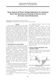
<strong>Magnetic</strong> <strong>Analysis</strong> <strong>Of</strong> <strong>Flat</strong> <strong>Ironless</strong> <strong>Rotor</strong> <strong>DC</strong> <strong>Micromotor</strong><br />
Norbert Szakály, Budapest University of Technology and Economics<br />
(01.09.2008, prof. Attila Halmai, Budapest University of Technology and Economics)<br />
Abstract<br />
This research is very important because<br />
nowadays the disk rotor micromotor is applied<br />
continually more frequently. I examine the magnetic<br />
circuit of a thin profile flat ironless rotor <strong>DC</strong><br />
micromotor (Falhauber Group Company product).<br />
The speciality of this disk construction gives the axial<br />
magnet ring-shaped permanent magnet and heartshaped<br />
coil.<br />
My aim is to make a finite elements model that is<br />
suitable for examination of the motor’s magnetic<br />
circuit, because the main parameter of motor’s<br />
rotation moment instruction is the magnetic flux<br />
density in then air gap. The current model possesses<br />
magnetic poles with concentrated parameter, but it is<br />
already suitable to modeling for magnetic flux<br />
density in the air gap.<br />
It is possible to define the optimal radial coil<br />
position with the help of the obtained results with<br />
simulation. Another possibility is to change other<br />
magnetic materials or the thickness of the magnet<br />
and air gap.<br />
2. Thin profile flat ironless rotor <strong>DC</strong><br />
micromotor<br />
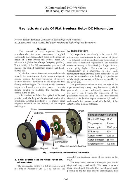
The constructed motor is a disk micromotor and<br />
the type is Faulhalber 2607T. You can see the<br />
<strong>XI</strong> International PhD Workshop<br />
OWD 2009, 17–20 October 2009<br />
Fig.1. Thin profile flat ironless rotor <strong>DC</strong> micromotor<br />
361<br />
1. Introductory<br />
My supervisor has already built several disk<br />
micromotor constructions in the course of years.<br />
The different construction shapes are the product of<br />
some kind of technical requirements. The technical<br />
requirements may be diversified, (e.g. longer lifetime,<br />
more rigidity, higher efficiency or more power).<br />
Unfortunately, it is impossible to meet each<br />
requirement unconditionally at the same time, so the<br />
motor that we received with the help of optimization<br />
of the single parameters, will always be suitable for<br />
the given task.<br />
The parameter-examination with the help of the<br />
experimental way is very costly because every single<br />
part should be prepared individually. Because of this,<br />
my aim is that I exam the connection of the<br />
parameters with the help of the finite-element<br />
simulation. As the first step of my research, I made a<br />
real motor’s fine element model with the help of the<br />
ANSYS finite element software.<br />
exploded constructional figure of the motor in the<br />
Fig.1.<br />
The ring-shaped magnet is four-pole (one whole<br />
ring) and magnetized axially. The rotor possesses<br />
three heart-shaped flat-coils. This thin-shape is made<br />
possible by the flat-coils and the axial magnet. The
oll of the motor obtains the current by means of the<br />
commutator and the brushes.<br />
Thanks for the four poles and the three coils, the<br />
commutation is necessary to keeping rotation after<br />
every thirty degree accomplishment. The three coils<br />
are connected with star-connection and it follows<br />
from this, two coils function at the all same time and<br />
the current does not flow through on the third coil.<br />
The rotation of the rotor is carried by the Lorentz<br />
force that has an affect on the progressive electrons<br />
in the coil.<br />
You can see in the Fig.2. the commutationprocess<br />
(twelve periods where the positive current<br />
direction is anti-clockwise direction) and the<br />
effective powers to the coils (A, B, C).<br />
Fig. 2. The commutation-process<br />
3. Finite-element model<br />
Mechanical, thermal and electromagnetic<br />
calculations are possible to be solved with the help<br />
of the ANSYS coupled-filed analyzes. The SOLID<br />
97 element type (Fig.3.) is the best-fit for this<br />
electromagnetic simulation. This element type is<br />
362<br />
suitable to determine the magnetic flux density,<br />
magnetic field intensity and the Maxwell force. In<br />
the course of the simulation, I applied the 3-D Static<br />
<strong>Magnetic</strong> MVP <strong>Analysis</strong> and I determined the 3D<br />
magnetic flux density of the motor.<br />
Fig. 3. SOLID 97 element type<br />
3.1 Geometry and Mesh<br />
The first step of making the finite element model<br />
was to complete the geometry. I made the motor’s<br />
three-dimension geometry in SolidWorks CAD<br />
software and then I imported the necessary<br />
components for the magnetic examination in the<br />
ANSYS software. You can see the meshed<br />
components in the Fig.4.<br />
Fig. 4. Assemblies<br />
I assembled the permanent magnet from four<br />
different components because of its poles. As the<br />
opposite-polar magnets pole-changing is not<br />
suddenly in reality, for this reason I put in a two<br />
millimeters wide pole-less material-proportion<br />
between the two poles, too. The coils are placed in<br />
the air gap. The places of brushes and for the rotorencoders<br />
are getting in shape on cutting of the back<br />
side end ring. These cuttings modify the emergence<br />
of the distribution for the magnetic induction in the<br />
circus, that’s why it will not be symmetric. I needed
to make a cube around the motor geometry, which<br />
fulfills the role of the surrounding air in the motor.<br />
3.2 The parameters of the material<br />
I defined permanent magnetic material properties<br />
for the permanent magnet poles. The material of the<br />
magnet was rare earth material (N45). I needed to<br />
define the value of the remanent induction and the<br />
relative permeability for the software. I summarized<br />
each material-feature values in the Tab.1. The end<br />
rings were described with non-linear B-H curve<br />
(Fig.5.).<br />
Material properties<br />
Tab.1.<br />
Assembly Material<br />
µr<br />
[-]<br />
H<br />
[kA/m]<br />
Windings Copper 1,039<br />
Magnet (N) N45 1,039 965<br />
Magnet (S) N45 1,039 -965<br />
Air Air 1<br />
End rings<br />
Non-linear soft<br />
magnetic material (Fig 5.)<br />
Fig.5. Non-linear soft magnetic material’s B-H curve<br />
4. Calculations<br />
As the result of the finite element simulation the<br />
distribution of stationary magnetic flux density inside<br />
the motor can be determined. The axial direction<br />
component in the magnetic induction distribution<br />
which is perpendicular for the coil is essential,<br />
because it generates the Lorentz force in the coils of<br />
the rotor. For this reason, I made the examinations<br />
in the middle of the air gap which is the middle plane<br />
of the coil at the same time, too.<br />
4.1 The magnetic induction distribution in<br />
the middle plane of the coil<br />
As one of the results of the simulation, I obtained<br />
that the maximal axial magnetic induction<br />
distribution in the air gap was the biggest in the 8-8,5<br />
mm radius region. In this region the maximal<br />
magnetic induction was 0,545 T. This is very<br />
363<br />
important for constructional-aspect because the<br />
radial segments of the coils are necessary to be<br />
placed to the biggest magnetic induction position in<br />
order that the biggest moment might be retrieved<br />
from the motor. The maximal value less ten per cent<br />
magnetic induction value is present in the 7-9,5 mm<br />
region that’s why the radial position of the coil is<br />
suitable to place here at this construction. You can<br />
see the emergent axial magnetic induction<br />
distribution in 8 mm radius circle in the Fig.6.<br />
Fig. 6. The axial magnetic induction distribution by the side of<br />
circle (R= 8 mm)<br />
4.2 The connection between the air gap and<br />
the thickness of the magnet<br />
The power of the motor is given by the features<br />
of the permanent magnet and the magnetic circuit<br />
arrangement (the thickness of the magnet and air<br />
gap). With helping of the simulation, I defined<br />
beside the constant motor-thickness, the values of<br />
the axial magnetic induction distribution by the side<br />
of radius as a function of the thickness changing for<br />
the magnet and air gap. For this I made fifteen<br />
different magnetic circles arrangements and<br />
simulations. To the definition of the air gap<br />
thickness is necessary the thickness of the coils and<br />
the distance between the coils and the end rings<br />
which is 0.2 mm in both side. This game is necessary<br />
that the coil should not friction. You can see the<br />
parameters of the fifteen different simulations in the<br />
Fig. 7.
You can see the values of the maximal axial<br />
magnetic induction distribution (Baxial) by the side of<br />
the radius (R) in case of the different relation of the<br />
la/lm in the Fig.8. In accordance with the established<br />
Baxial is the lowest value in case of the thin magnet<br />
(la/lm=1,77). The maximal Baxial may be caused in<br />
case of la/lm=0,33 ratio. On the diagram it can be<br />
seen very well that the ten per cent deviation from<br />
the maximal value in case of each arrangement is<br />
between 7-9,5 mm radius.<br />
Fig. 8. B axial vs. Radius and la/lm<br />
Fig. 7. The variation of the magnet circuit parameters<br />
364<br />
If I take the average deviation of the values inside<br />
the ten per cent, and I illustrate these values in the<br />
ratio of the la/lm, I will obtain the next diagram<br />
(Fig.9.). Looking for an approximate function<br />
between the ratios of the thickness and the axial<br />
magnetic induction values; I found the following<br />
connection (1):<br />
Baxial = - 0,2168Ln( la lm)<br />
+ 0,4789 (1)<br />
Fig. 9. B axial vs. la/lm
5. Conclusions<br />
With the help of the simulations until now, I<br />
successfully did the examination of the motor<br />
magnet circuit. These results made possible to define<br />
the magnetic induction distribution in the middle<br />
plane of the air gap. With the help of these results,<br />
there is an opportunity to choose the suitable coil<br />
geometry. By reason of the results, the best flux<br />
connection I got in the segment between 7-9,5 mm<br />
radius, that’s why the radial segment of the coils<br />
need to be put here.<br />
The next aim is to determine the Lorentz force<br />
with the help of the simulation which is effective in<br />
the coils in given angle-location, and that means I<br />
will determine the starting moment of the motor.<br />
365<br />
Bibliography<br />
[1] Jacek F. Gieras, Mitchell Wing: Permanent magnet<br />
motor technology: design and applications,<br />
ISBN: 0-8247-0739-1<br />
[2] Austin Hughes: Electric Motors and Drives, Third<br />
Edition: Fundamentals, ISBN: 0-7506-4718-3<br />
[3] Faulhalber Miniature Drive Systems:<br />
www.faulhaber.com<br />
[4] Sham Tickoo: ANSYS 11.0 for Designers, ISBN:<br />
1-9327-0958-4<br />
Author<br />
Norbert Szakály<br />
Budapest University of<br />
Technology and Economics<br />
Mőegyetem rkp. 3.<br />
H-1111, Budapest<br />
email: szakaly@mogi.bme.hu