Some Aspects Of Pulse Voltage Regulation For Induction Motor Soft ...
Some Aspects Of Pulse Voltage Regulation For Induction Motor Soft ...
Some Aspects Of Pulse Voltage Regulation For Induction Motor Soft ...

Create successful ePaper yourself
Turn your PDF publications into a flip-book with our unique Google optimized e-Paper software.
<strong>Some</strong> <strong>Aspects</strong> <strong>Of</strong> <strong>Pulse</strong> <strong>Voltage</strong> <strong>Regulation</strong> <strong>For</strong> <strong>Induction</strong><br />
<strong>Motor</strong> <strong>Soft</strong> Starting And Braking In Electric Drives<br />
<strong>Of</strong> Crane Travel Mechanisms<br />
Vasilyev Dmitry, Belorussian National Technical University<br />
(01.12.2006, prof. Firago Bronislav, Belorussian National Technical University)<br />
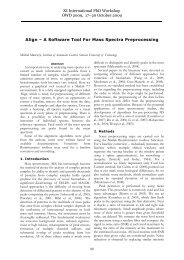
Abstract<br />
In this paper the application of pulse voltage<br />
regulation for soft starting and braking of induction<br />
motors of crane traveling mechanisms is discussed.<br />
Shortcomings of phase voltage regulators - thyristor<br />
softstarters - and advantages of pulse voltage<br />
regulators (PVR) are analyzed. Three types of PVR<br />
power circuit structures are described and compared.<br />
Quasi-frequency control at underspeed operation of<br />
a crane induction motor supplied with PVR is<br />
considered. The research of soft starting and braking<br />
modes as well as quasi-frequency control of a crane<br />
induction motor has been performed with the help<br />
of Matlab simulation model of a thyristor softstarter<br />
and PVR based on three mains power switches and a<br />
shunt diode bridge.<br />
1. Introduction to the problem<br />
Crane equipment is widely used in various fields<br />
of industry, for example, in metallurgical production,<br />
port terminals, warehouses and etc. A certain field of<br />
application determines crane mechanism<br />
construction features, functional characteristics and<br />
also operating requirements. However crane<br />
equipment has some common features and therefore<br />
can be defined by a number of general requirements.<br />
Since all the technological operations of crane<br />
mechanisms are performed by means of electric<br />
drives, crane equipment functionality requirements<br />
first of all refer to crane electric drives. Basic<br />
requirements include high production efficiency,<br />
reliability, fail-safe operation and maintenance<br />
simplicity.<br />
These basic requirements can be extended further<br />
to comply with the following technical conditions:<br />
1) Operation at steady underspeeds which can<br />
be achieved with stiff speed-torque characteristics of<br />
the electric drives,<br />
2) <strong>Soft</strong> starting and breaking with set<br />
acceleration and deceleration during operation at any<br />
speed of working range,<br />
3) Efficiency of starting/breaking modes and<br />
speed regulation,<br />
XI International PhD Workshop<br />
OWD 2009, 17–20 October 2009<br />
403<br />
4) Reduction of impact torques and starting<br />
currents in mechanical gears.<br />
Nowadays frequency converters with the<br />
induction motors are widely used in the variable<br />
speed electric drives of crane mechanisms – crane<br />
traveling and hoisting mechanisms. Such a controlled<br />
electric drive undoubtedly meets most of the<br />
mechanism’s operating requirements but on the<br />
other hand is considerably more expensive than the<br />
uncontrolled one because of the frequency converter<br />
price which is three-five times higher the price of an<br />
induction motor.<br />
When there is no need in full conformity with the<br />
above mentioned technological requirements (such<br />
as speed control ability) for a certain crane<br />
mechanism, for example, crane trolley traveling<br />
mechanism, cheaper and technologically simple soft<br />
starter device can be used as an alternative to a<br />
frequency converter.<br />
2. Phase voltage regulation of an<br />
induction motor<br />
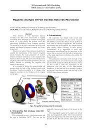
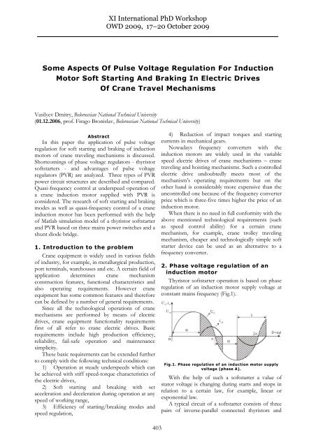
Thyristor softstarter operation is based on phase<br />
regulation of an induction motor supply voltage at<br />
constant mains frequency (Fig.1).<br />
Fig.1. Phase regulation of an induction motor supply<br />
voltage (phase A).<br />
With the help of such a softstarter a value of<br />
stator voltage is changing during starts and stops in<br />
relation to a certain law, for example, linear or<br />
exponential law.<br />
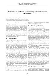
A typical circuit of a softstarter consists of three<br />
pairs of inverse-parallel connected thyristors and
allows controlling softstarter output voltage by<br />
changing the thyristor firing angle. Power circuit of<br />
such a thyristor softstarter is presented in Fig. 2.<br />
Fig.2. Power circuit of a typical thyristor softstarter.<br />
As a result of the thyristor softstarter application<br />
a negative impact of electromagnetic transients on<br />
the induction motor performance is weakened with<br />
the reduction of impact torques and starting<br />
currents. However due to the delayed start-up of the<br />
induction motor supplied with a softstarter and its<br />
extended total starting time energy losses during the<br />
induction motor transients tend to increase if<br />
compared with its direct starting with nominal mains<br />
voltage [1].<br />
Other shortcomings of a thyristor softstarter<br />
involve substantial distortions of a sinusoidal voltage<br />
waveform supplying the induction motor and a lag<br />
shift angle for the first current harmonic. The output<br />
voltage curve of a thyristor softstarter contains<br />
higher harmonics leading to the power factor<br />
decrease [1].<br />
Better harmonics content of the output voltage,<br />
absence of a lag shift angle in the first current<br />
harmonic waveform, less energy losses and therefore<br />
greater number of switching frequency can be<br />
obtained with the use of a pulse voltage regulator<br />
(PVR) operated on full-controlled power switches<br />
such as IGBT.<br />
3. <strong>Pulse</strong> voltage regulation of an<br />
induction motor<br />
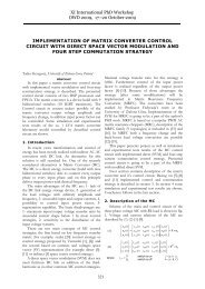
<strong>Pulse</strong> regulation of the induction motor supply<br />
voltage is carried out by changing the width (in<br />
relation to a certain law) and number of voltage<br />
pulses, i.e. IGBTs switching frequency. Half-period<br />
of PVR output voltage curve formed with 5 pulses is<br />
shown in Fig. 3. From [2] one can draw a conclusion<br />
that better harmonics content of the PVR output<br />
voltage can be achieved by increasing the number of<br />
voltage pulses. The higher harmonics amplitudes are<br />
decreased significantly with growth of the switching<br />
frequency. The author’s research in [2] also proves<br />
that the application of PVR provides less energy<br />
404<br />
losses in the induction motor transients than during<br />
its phase voltage regulation.<br />
Fig.3. A half-period example of PVR output voltage<br />
curve (formed with 5 pulses).<br />
Power circuit of a pulse voltage regulator consists<br />
of a certain number of supply mains power switches<br />
and shunt power switches. The latter are used for<br />
shunting of the induction motor stator windings<br />
during the off-state of the supply mains power<br />
switches. Each power switch is a pair of inverseparallel<br />
connected IGBT transistors with bypass<br />
diodes.<br />
Depending on the number of power switches<br />
used for pulse voltage regulation and induction<br />
motor shunting various operational PVR power<br />
circuits can be built. The authors of this paper have<br />
considered three variants of PVR power circuit<br />
structures.<br />
The first one consists of six power switches:<br />
3 supply mains power switches, 3 shunt power<br />
switches - one for each induction motor winding.<br />
Such a power circuit is completely symmetrical in<br />
relation to the output phase voltages and currents<br />
although rather expensive due to the increased<br />
number of power switches.<br />
The second type of PVR power circuit includes<br />
four power switches (2 supply mains power switches,<br />
2 shunt power switches for interphase motor<br />
windings shunting) and therefore is more costeffective<br />
than the previous one. This power circuit<br />
has asymmetrical structure and therefore causes<br />
output phase voltages and currents asymmetry.<br />
The third type of PVR power circuit consists of<br />
three supply mains power switches (one for each<br />
supply mains phase), a diode shunt bridge with one<br />
unidirectional transistor to operate the shunting<br />
process. This type of PVR power circuit has<br />
combined the advantages of the previous two<br />
structures. It is symmetrical but at the same time<br />
consists of a fewer number of power switches hence<br />
is less expensive.<br />
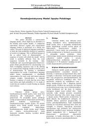
The power circuit of the pulse voltage regulator<br />
with three power switches (transistors T1-T6), a<br />
shunt diode bridge D1-D6 and one unidirectional<br />
transistor T7 is shown in Fig. 4. Operation of the<br />
supply mains transistors T1-T6 provides energy<br />
exchange between the load and the mains. When<br />
they are switched off transistor T7 shunts the<br />
induction motor windings with the diode bridge.
Fig.4. PVR with three power switches and a shunt<br />
diode bridge.<br />
Further research and simulation of the induction<br />
motor soft starting and breaking as well quasifrequency<br />
control study is based on the latter PVR<br />
power circuit structure.<br />
<strong>For</strong> a more detailed description and comparison<br />
of possible PVR power circuit structures please refer<br />
to [3].<br />
4. Quasi-frequency control of an<br />
induction motor supplied with<br />
pulse voltage regulator<br />
Functionality of a pulse voltage regulator is<br />
extended with the application of an induction motor<br />
quasi-frequency control ability. Such an improved<br />
soft starter device would allow not only the<br />
reduction of impact torques and starting currents but<br />
also provide the operation of an induction motor at<br />
underspeed. PVR with this feature can be used in the<br />
crane electric drives for smooth stopping and precise<br />
positioning of the crane traveling mechanisms<br />
instead of an expensive frequency converter.<br />
405<br />
Thyristor softstarter output voltage curve during<br />
quasi-frequency control of an induction motor is<br />
shown in Fig. 5. The formation of the induction<br />
motor supply voltage consists of a series of positive<br />
and negative supply mains voltage half-waves, which<br />
are formed according to the alternating sign<br />
switching function.<br />
Fig.5. Thyristor softstarter output voltage curve<br />
during quasi-frequency control.<br />
The sign of this switching function defines<br />
output voltage curve polarity during the quasifrequency<br />
control. The period of the switching<br />
function sets the number of positive and negative<br />
supply mains voltage half-waves in it.<br />
The formation of the PVR output voltage curve<br />
for phase A during quasi-frequency control is shown<br />
in Fig. 6. According to the PVR power circuit<br />
structure in Fig. 4 transistors T1, T2 take part in the<br />
formation of the PVR voltage pulses for phase A,<br />
while transistor T7 performs shunting of the motor.<br />
Fig.6. PVR output voltage curve during quasi-frequency control.
Transistor T7 operates only as a shunt when either<br />
T1 or T2 is in off state so that the circuit current<br />
could decrease to zero. The same switching<br />
algorithm during quasi-frequency control is applied<br />
to the remaining power switches of phase B and C.<br />
In general the formation of any PVR output<br />
voltage curve during quasi-frequency control of an<br />
induction motor is performed with a certain<br />
switching sequence of the mains and shunt IGBT<br />
transistors according to the desired quasi frequency.<br />
To variate quasi-voltage value one should change the<br />
supply mains transistors pulse width.<br />
5. Simulation results<br />
The research of the induction motor soft starting<br />
and braking for phase and pulse voltage regulation<br />
has been performed via Matlab simulation models.<br />
PVR simulation model has been developed<br />
according to the power circuit with three power<br />
1<br />
Usa<br />
2<br />
Usb<br />
3<br />
Usc<br />
2<br />
T2a_pulse<br />
1<br />
T1a_pulse<br />
3<br />
T1b_pulse<br />
4<br />
T2b_pulse<br />
6<br />
T4a_pulse<br />
5<br />
T3a_pulse<br />
7<br />
T3b_pulse<br />
8<br />
T4b_pulse<br />
10<br />
T6a_pulse<br />
9<br />
T5a_pulse<br />
11<br />
T5b_pulse<br />
12<br />
T6b_pulse<br />
g<br />
C<br />
g<br />
C<br />
g<br />
C<br />
T1 T2<br />
E<br />
E<br />
T3 T4<br />
E<br />
T5 T6<br />
E<br />
E<br />
E<br />
g<br />
C<br />
g<br />
C<br />
g<br />
C<br />
406<br />
switches and a shunt diode bridge (Fig. 7). The<br />
parameters of the special crane induction motor<br />
4MTKF160LB8 (11kW, 380/220V, 40% duty cycle)<br />
designed for intermittent operation mode have been<br />
used during the simulation.<br />
<strong>Pulse</strong> voltage regulation of the crane induction<br />
motor 4MTKF160LB8 has been performed<br />
according to the linear and exponential 1st harmonic<br />
voltage variation.<br />
PVR output voltage and current curves are<br />
presented in Fig. 8. The induction motor<br />
4MTKF160LB8 speed curves for various starting<br />
current limitation settings are presented in Fig. 9.<br />
The authors have also performed simulation of<br />
the crane induction motor 4MTKF160LB8<br />
underspeed operation at quasi-frequency of 8,33 Hz<br />
for the same PVR power circuit structure.<br />
The results of quasi-frequency control simulation are<br />
presented in Fig. 10.<br />
Tm<br />
LOAD<br />
U1a<br />
U1b<br />
U1c<br />
Shunt IGBT pulses<br />
OR<br />
Shunt diode bridge<br />
Tm<br />
A<br />
B<br />
C<br />
Crane <strong>Induction</strong> <strong>Motor</strong><br />
4MTKF160LB8<br />
A<br />
Shunt IGBT T7<br />
Fig.7. Matlab simulation model of PVR with 3 power switches and a shunt diode bridge.<br />
To provide steady underspeed operation of the<br />
induction motor at the reduced frequency it is<br />
imperative to maintain flux linkage at constant level<br />
by decreasing the quasi-frequency control voltage<br />
proportionally to the reduced frequency. Otherwise,<br />
an oversaturation of the induction motor magnetic<br />
system will occur.<br />
Quasi-frequency control results in the motor<br />
underspeed fluctuations (Fig. 10) because of the<br />
pulse nature of stator current and motor torque<br />
during this operating mode. Underspeed fluctuations<br />
lead to the induction motor vibrations. Moreover<br />
with the relatively high motor torque (close to its<br />
nominal value), current amplitudes during quasifrequency<br />
control of the induction motor increase up<br />
to 200% and even higher. Therefore quasi-frequency<br />
control should be applied for the induction motor<br />
low speed operation for a short period of time.<br />
g<br />
C<br />
+<br />
B<br />
E<br />
-<br />
C<br />
m
Fig.8. Output phase voltages (a) and currents (b) of PVR with 3 power switches<br />
and a shunt diode bridge.<br />
Fig.9. 4MTKF160LB8 induction motor speed curves for 3 starting current<br />
limitation settings.<br />
407
Fig. 10. 4MTKF160LB8 induction motor speed curve with underspeed operation<br />
at 8,33 Hz during quasi-frequency control.<br />
6. Conclusions<br />
<strong>Pulse</strong> voltage regulator based on a power circuit<br />
with 3 power switches and a shunt diode bridge has<br />
a number of obvious advantages over the thyristor<br />
voltage regulator such as:<br />
- reduced energy losses in the induction motor<br />
transients due to symmetrical power circuit structure<br />
and lack of output voltages and currents phase<br />
asymmetry;<br />
- lowered impact on supply mains due to the<br />
better harmonic content of the PVR output voltage<br />
and current curves;<br />
- increased power factor and lack of 1st harmonic<br />
current shift angle;<br />
- quasi-frequency control ability for the induction<br />
motor steady operation at underspeeds.<br />
PVR with quasi-frequency control ability if<br />
compared to thyristor voltage regulator can be<br />
considered an improved softstarter device and is a<br />
cheaper alternative to a frequency converter<br />
provided there are no strict speed control<br />
requirements for a certain technological mechanism.<br />
<strong>For</strong> example, it would be reasonable and costeffective<br />
to apply such PVR in the crane electric<br />
drive of a trolley traveling mechanism.<br />
Bibliography<br />
[1] Firago Bronislav, Vasilyev Dmitry, Pawlaczyk<br />
Leszek: Regulirovanie naprjazenija asinchronnogo<br />
dvigatelja impulsnymi metodami dlja mjagkogo puska i<br />
tormozenija, II mezdunarodnaja naucnotechniceskaja<br />
konferencija ″Organizacionnotechniceskoe<br />
upravlenie v mezotraslevych<br />
kompleksach″, 20-21 nojabrja 2007, Belorusskij<br />
Gosudarstvennyj Technologiceskij Universitet,<br />
Minsk, s. 213-220<br />
408<br />
[2] Firago Bronislav, Vasilyev Dmitry, Pawlaczyk<br />
Leszek: Zastosowanie impulsowego regulatora napięcia<br />
dla miękkiego rozruchu i hamowania silników, prace<br />
Naukowe Instytutu Maszyn, Napedow i<br />
Pomiarow Elektrycznych, nr 62, Studia i<br />
Materialy nr 28, s. 378-386, Politechnika<br />
Wroclawska, Wroclaw, 2008<br />
[3] Strzelecki Ryszard, Supronowicz Henryk:<br />
Wspólczynnik mocy w systemach zasilania pradu<br />
przemiennego i metody jego poprawy, oficyna<br />
Wydawnicza Politechniki Warszawskiej,<br />
Warszawa, 2000. – 452 s<br />
Authors:<br />
PhD student<br />
Vasilyev Dmitry<br />
Belorussian National<br />
Technical University<br />
F. Skaryna 65<br />
Minsk 220027<br />
Belarus<br />
email: dmy@tut.by<br />
Prof. Firago Bronislav<br />
Belorussian National<br />
Technical University<br />
F. Skaryna 65<br />
Minsk 220027<br />
Belarus<br />
email: dmy@tut.by