Some Aspects Of Pulse Voltage Regulation For Induction Motor Soft ...
Some Aspects Of Pulse Voltage Regulation For Induction Motor Soft ...
Some Aspects Of Pulse Voltage Regulation For Induction Motor Soft ...

You also want an ePaper? Increase the reach of your titles
YUMPU automatically turns print PDFs into web optimized ePapers that Google loves.
allows controlling softstarter output voltage by<br />
changing the thyristor firing angle. Power circuit of<br />
such a thyristor softstarter is presented in Fig. 2.<br />
Fig.2. Power circuit of a typical thyristor softstarter.<br />
As a result of the thyristor softstarter application<br />
a negative impact of electromagnetic transients on<br />
the induction motor performance is weakened with<br />
the reduction of impact torques and starting<br />
currents. However due to the delayed start-up of the<br />
induction motor supplied with a softstarter and its<br />
extended total starting time energy losses during the<br />
induction motor transients tend to increase if<br />
compared with its direct starting with nominal mains<br />
voltage [1].<br />
Other shortcomings of a thyristor softstarter<br />
involve substantial distortions of a sinusoidal voltage<br />
waveform supplying the induction motor and a lag<br />
shift angle for the first current harmonic. The output<br />
voltage curve of a thyristor softstarter contains<br />
higher harmonics leading to the power factor<br />
decrease [1].<br />
Better harmonics content of the output voltage,<br />
absence of a lag shift angle in the first current<br />
harmonic waveform, less energy losses and therefore<br />
greater number of switching frequency can be<br />
obtained with the use of a pulse voltage regulator<br />
(PVR) operated on full-controlled power switches<br />
such as IGBT.<br />
3. <strong>Pulse</strong> voltage regulation of an<br />
induction motor<br />
<strong>Pulse</strong> regulation of the induction motor supply<br />
voltage is carried out by changing the width (in<br />
relation to a certain law) and number of voltage<br />
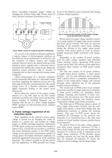
pulses, i.e. IGBTs switching frequency. Half-period<br />
of PVR output voltage curve formed with 5 pulses is<br />
shown in Fig. 3. From [2] one can draw a conclusion<br />
that better harmonics content of the PVR output<br />
voltage can be achieved by increasing the number of<br />
voltage pulses. The higher harmonics amplitudes are<br />
decreased significantly with growth of the switching<br />
frequency. The author’s research in [2] also proves<br />
that the application of PVR provides less energy<br />
404<br />
losses in the induction motor transients than during<br />
its phase voltage regulation.<br />
Fig.3. A half-period example of PVR output voltage<br />
curve (formed with 5 pulses).<br />
Power circuit of a pulse voltage regulator consists<br />
of a certain number of supply mains power switches<br />
and shunt power switches. The latter are used for<br />
shunting of the induction motor stator windings<br />
during the off-state of the supply mains power<br />
switches. Each power switch is a pair of inverseparallel<br />
connected IGBT transistors with bypass<br />
diodes.<br />
Depending on the number of power switches<br />
used for pulse voltage regulation and induction<br />
motor shunting various operational PVR power<br />
circuits can be built. The authors of this paper have<br />
considered three variants of PVR power circuit<br />
structures.<br />
The first one consists of six power switches:<br />
3 supply mains power switches, 3 shunt power<br />
switches - one for each induction motor winding.<br />
Such a power circuit is completely symmetrical in<br />
relation to the output phase voltages and currents<br />
although rather expensive due to the increased<br />
number of power switches.<br />
The second type of PVR power circuit includes<br />
four power switches (2 supply mains power switches,<br />
2 shunt power switches for interphase motor<br />
windings shunting) and therefore is more costeffective<br />
than the previous one. This power circuit<br />
has asymmetrical structure and therefore causes<br />
output phase voltages and currents asymmetry.<br />
The third type of PVR power circuit consists of<br />
three supply mains power switches (one for each<br />
supply mains phase), a diode shunt bridge with one<br />
unidirectional transistor to operate the shunting<br />
process. This type of PVR power circuit has<br />
combined the advantages of the previous two<br />
structures. It is symmetrical but at the same time<br />
consists of a fewer number of power switches hence<br />
is less expensive.<br />
The power circuit of the pulse voltage regulator<br />
with three power switches (transistors T1-T6), a<br />
shunt diode bridge D1-D6 and one unidirectional<br />
transistor T7 is shown in Fig. 4. Operation of the<br />
supply mains transistors T1-T6 provides energy<br />
exchange between the load and the mains. When<br />
they are switched off transistor T7 shunts the<br />
induction motor windings with the diode bridge.