The Critical Whirling Speeds and Natural Vibrations of a ... - aerade
The Critical Whirling Speeds and Natural Vibrations of a ... - aerade
The Critical Whirling Speeds and Natural Vibrations of a ... - aerade

You also want an ePaper? Increase the reach of your titles
YUMPU automatically turns print PDFs into web optimized ePapers that Google loves.
MINISTRY OF SUPPLY<br />
AERONAUTICAL RESEARCH COUNCIL<br />
REPORTS AND MEMORANDA<br />
/,<br />
:.NATIONAL AEROi~AUTICAL<br />
E8TA BLESH[I~ E NT,<br />
7 2 MAR lss~<br />
LIBRA. ~-~':~Y<br />
<strong>The</strong> <strong>Critical</strong> <strong>Whirling</strong> <strong>Speeds</strong> <strong>and</strong> <strong>Natural</strong><br />
<strong>Vibrations</strong> <strong>of</strong> a Shaft Carrying a<br />
Symmetrical Rotor<br />
By<br />
E. DOWNHAM, B.Sc. (Eng.), A.F.R.Ae.S.<br />
Crown Copyright Reserved<br />
LONDON' HER MAJESTY'S STATIONERY OFFICE<br />
1954<br />
FOUR SHILLINGS NET<br />
R. & M. No. 2854<br />
(13 #17)<br />
A.R.C. Technical Report<br />
,, ~ . ,,~.~:; ~ . . . . ,.<br />
[ : [ , ~<br />
L .............................. t ......................... ';
<strong>The</strong> <strong>Critical</strong> <strong>Whirling</strong> <strong>Speeds</strong> <strong>and</strong> <strong>Natural</strong> <strong>Vibrations</strong><br />
<strong>of</strong> a Shaft Carrying a Symmetrical Rotor<br />
By<br />
E. DOWNHAM, B.Sc. (Eng.), A.F.R.Ae.S.<br />
COMMUNICATED BY THE PRINCIPAL DIRECTOR OF SCIENTIFIC RESEARCH (AIR),<br />
MINISTRY OF SUPPLY<br />
Reports <strong>and</strong> Memor<strong>and</strong>a IVo. 2 854<br />
, -Vt:~-2 . .............. . . . . .<br />
• " ~ n ,~-',~ :oR ,a,<br />
December, I 9 5 © !i "1 ~" :' ~: ";: "'~'~'": "i<br />
Summary.--<strong>The</strong> experiments described in this report are part <strong>of</strong> a programme <strong>of</strong> model experimenfs-'-d~signe---=dto ~ .........<br />
establish an accurate method for calculating the critical whirling speeds <strong>of</strong> complex systems.<br />
<strong>The</strong> critical whMing speeds <strong>and</strong> natural vibrations <strong>of</strong> a single shaft ~flexibly supported <strong>and</strong> carrying a flexible rotor<br />
<strong>of</strong> appreciable moment <strong>of</strong> inertia have been investigated' <strong>and</strong> good agreement has been obtained between experimental<br />
<strong>and</strong> cMculated results for the rotating system. <strong>The</strong>re is some discrepancy between calculated <strong>and</strong> experimental results<br />
for the vibration <strong>of</strong> the non-rotating system, which is thought to be due to the operational characteristics <strong>of</strong> the flexible<br />
bearing.<br />
1. Introduction.--<strong>The</strong> problems associated with shaft whirling have already been discussed<br />
by the author in a previous report 1, <strong>and</strong> preliminary experiments have been carried out on a<br />
model rig s , confirming the fundamental theory <strong>of</strong> shaft whirling.<br />
<strong>The</strong> experiments described in the report are part <strong>of</strong> a programme <strong>of</strong> model experiments 1<br />
designed to establish an accurate method for calculating the critical whirling speeds <strong>of</strong> complex<br />
systems. <strong>The</strong> particular system investigated is essentially a rotor mounted on a cantilever<br />
shaft having an additional lateral support, the whole having degrees <strong>of</strong> flexibility introduced<br />
additional to that <strong>of</strong> the shaft itself. Flexibility <strong>of</strong> known value is introduced symmetrically<br />
at the lateral support. Flexibility is also provided in the rotor, which has four flexible arms<br />
enabling itto distort out <strong>of</strong> the plane <strong>of</strong> rotation. <strong>The</strong> whole system has kinetic symmetry,<br />
<strong>and</strong> the moment <strong>of</strong> inertia <strong>of</strong> the rotor can be varied without changing its mass.<br />
<strong>The</strong> dynamics <strong>of</strong> the system, when vibrating <strong>and</strong> whirling, were investigated theoretically<br />
using methods suggested by Morris "a <strong>and</strong> based on the Jeffcott theory <strong>of</strong> shaft whirling ~,5 (1919),<br />
the forms <strong>of</strong> vibration considered involving only shaft bending without torsion. It is shown<br />
that for this particular system there will be one critical whirling speed which increases as the<br />
inertia <strong>of</strong> the rotor increases. <strong>The</strong> lower natural frequency <strong>of</strong> vibration <strong>of</strong> the non-rotating<br />
system is shown to decrease as the inertia <strong>of</strong> tile rotor increases. For a particular rotational<br />
speed <strong>of</strong> the rotating system the natural vibrations will be circular, there being four resonant<br />
frequencies which vary with rotational speed. <strong>The</strong>se circular vibrations are exponentially<br />
stable <strong>and</strong> a critical whirling speed occurs only when the frequency <strong>of</strong> the forced vibration due<br />
to rotor unbalance coincides with a natural frequency <strong>of</strong> vibration <strong>of</strong> the rotating system.<br />
<strong>The</strong> effect <strong>of</strong> tile inertia couples due to the rotor, on the deflection forms for the whirling<br />
system, <strong>and</strong> for the non-rotating system vibrating naturally, was obtained experimentally;<br />
<strong>and</strong> these deflection forms were compared with that <strong>of</strong> the non-rotating system due to a static<br />
load at the point <strong>of</strong> attachment <strong>of</strong> the rotor.<br />
* R.A.E. Report Structures 97, received 16th April, 1951.<br />
1
<strong>The</strong> natural frequencies <strong>of</strong> the non-rotating system <strong>and</strong> the-critical whirling speeds were<br />
calculated for different amounts <strong>of</strong> rotor inertia, <strong>and</strong> the results compared with measured critical<br />
whirling speeds <strong>and</strong> natural frequencies. <strong>The</strong> comparison gives good agreement between<br />
calculated <strong>and</strong> measured critical speeds but the calculated natural frequencies <strong>of</strong> the non-rotating<br />
system were approximately 10 per cent below those measured. This is considered to be due to<br />
the outrigger bearing imposing a greater constraint on the non-rotating system when vibrating<br />
transversely than on the rotating system when whirling, thus causing a change in the mode <strong>of</strong><br />
vibration <strong>and</strong> an increase in the natural frequency.<br />
Following these investigations the natural frequencies <strong>of</strong> the rotating system were calculated<br />
over a range <strong>of</strong> shaft speeds. Two sets <strong>of</strong> calculations were made, one assuming the rotor arms<br />
to be rigid, <strong>and</strong> another allowing for the flexibility <strong>of</strong> the arms. <strong>The</strong>se frequencies were then<br />
measured experimentally. A comparison between calculated <strong>and</strong> measured frequencies gave<br />
good agreement, <strong>and</strong> it was shown that the allowance for flexibility in the rotor arms increased<br />
the accuracy <strong>of</strong> the calculations, especially when the measured natural frequencies <strong>of</strong> the system<br />
were remote from the natural frequency <strong>of</strong> the rotor arms. It is concluded therefore, that<br />
providing the constraints in a system are known, accurate calculations <strong>of</strong> the critical whirling<br />
speed <strong>and</strong> natural frequencies can be made using the theoretical treatment described.<br />
2. <strong>The</strong>oretical I~¢vestigations.--2.1. Analytical Treatment.--2.1.1. <strong>The</strong> whirling condition.-<br />
In this case the dynamics <strong>of</strong> a shaft (Fig. 1) supported in bearings <strong>of</strong> symmetrical stiffness<br />
carrying a load W <strong>of</strong> mass m <strong>and</strong> <strong>of</strong> appreciable moments <strong>of</strong> inertia a, a, c (c being the polar<br />
moment <strong>and</strong> a the moment about a diameter in lb in. sec ~ units) are considered.<br />
In Fig. 1 the line OZ is drawn through 0 the point <strong>of</strong> attachment between the rotor <strong>and</strong> the<br />
shaft parallel to the centre-line <strong>of</strong> the bearings. <strong>The</strong> point O' represents the displaced position<br />
<strong>of</strong> 0 having co-ordinates X <strong>and</strong> Y relative to the major (fixed) axes OX <strong>and</strong> OY.<br />
<strong>The</strong> point G represents the c.g. <strong>of</strong> the rotor assumed to be displaced an amount h from O' in<br />
the plane XOY. <strong>The</strong> motion <strong>of</strong> the system is considered relative to the three axes Gx, Gy <strong>and</strong><br />
Gz drawn parallel to the major axes OX, O Y <strong>and</strong> OZ.<br />
<strong>The</strong> positions <strong>of</strong> the principle axes <strong>of</strong> the rotor in a general displacement <strong>of</strong> the system are<br />
represented by GA, GB <strong>and</strong> GC, the inertias relative to these axes being a, a <strong>and</strong> c respectively.<br />
<strong>The</strong> positions <strong>of</strong> these axes is determined by imagining first a small rotation # in the xz-plane<br />
about the y-axis, then a small rotation 0 about the displaced x-axis <strong>and</strong> finally a rotation ~t<br />
about the axis GC.<br />
<strong>The</strong> rotations ~ <strong>and</strong> 0 are assumed to be small which would be the case in practice <strong>and</strong> ~ is<br />
the angular speed <strong>of</strong> the shaft.<br />
<strong>The</strong> instantaneous angular velocities about the axes AG, BG <strong>and</strong> CG are represented by<br />
0)1, 0)2, 0)3 respectively <strong>and</strong> are obtained by summing the components <strong>of</strong> the angular velocities<br />
#, 6 <strong>and</strong> f2 in the planes BCG, ACG <strong>and</strong> ABG respectively.<br />
Thus 0)1 ---- ~ sin ~t -- 6 cos ~t<br />
0), = # cos ~gt + $ sin ~t ~ . . . . . . . . . . . . . (1)<br />
0) 3 ~ if2<br />
<strong>The</strong> angular momenta due to the angular velocities <strong>of</strong> equations (1) are respectively aol,<br />
a0)2 <strong>and</strong> c0)3 <strong>and</strong> therefore the component angular momenta in the directions y to z <strong>and</strong> z to x<br />
are given by<br />
h, ---- a0)1 cos ~t -- a~o~ sin ~t + c0)3 •<br />
<strong>and</strong> hy = a0)1 sin ~t + a0)2 cos ~t + c0)8 0<br />
2<br />
. . . . . . . . (2)
Substituting for ~1, ~o~ <strong>and</strong> ~3 from (1) in (2) gives<br />
h, = -- a0 + c~gq~, .. ..<br />
hy = a# -/c~90 . . . . . . .<br />
a t<br />
• O<br />
• •<br />
• •<br />
• •<br />
• •<br />
• •<br />
• o<br />
• n<br />
• •<br />
.. (3)<br />
.. (4)<br />
<strong>The</strong> co-ordinates <strong>of</strong> G relative to the axes OX <strong>and</strong> OY will be X- h cos (~gt + ~)<br />
<strong>and</strong> Y -- h sin (zgt + ~) respectively where ~ is the angle between O'G <strong>and</strong> GA <strong>and</strong> (tgt + ~)<br />
is the angle between O'G <strong>and</strong> GX. Since h is small it may be assumed that the following forces<br />
will act on the shaft at 0'.<br />
(a) An inertia force -- m[X + hi? ~ cos (gt + ~)] in the direction <strong>of</strong> the X axis . . . . (5)<br />
(b) A couple due to the change <strong>of</strong> angular momentum -- hy ---= -- (a# + c~9~) about an<br />
axis through O' parallel to Gy in the direction z to x . . . . . . . . . . (6)<br />
(c) An inertia force -- m[Y + h~92 sin (t?t + ~)] in the direction <strong>of</strong> the Y axis .. (7)<br />
(d) A couple h, = -- (a0 -- ct?~b) about an axis through O' parallel to Gx in the direction<br />
z to y . . . . . . . . . . . . . . . . . . . . . . . . (8)<br />
<strong>The</strong> equations <strong>of</strong> motion are therefore<br />
X = -- m[R + h~Q 2 COS (~t .A[_ ~])~Yll -- (a# + Cff20)Zll . . . . . . (9)<br />
O = -- J'J~[X -7[- h~ 2 COS (gt + ~)IZll -- (6~¢ + C90)~11 . . . . . . (10)<br />
Y = -- m[52 + hi? 2 sin (gt + V)]Yn -- (aO -- c9¢)z~t . . . . . . (11)<br />
0 = -- m[~ ~ + h9 2 sin (gt + ~)~zll -- (aO -- c9¢)¢11 . . . . . . (12)<br />
where Yn is linear deflection due to unit load at the point <strong>of</strong> attachment<br />
¢11 Angular deflection due to unit couple at the point <strong>of</strong> attachment<br />
z~1 Angular deflection due to unit load at the point <strong>of</strong> attachment<br />
= linear deflection due to unit couple at the point <strong>of</strong> attachment<br />
A particular solution <strong>of</strong> equations (9), (10), (11) <strong>and</strong> (12) will be <strong>of</strong> the form<br />
X = X0 cos (zgt + V) Y = Xo sin (gt + v)<br />
= q~0 cos (zgt + V) 0 ---- q~0 sin (tgt + V)<br />
<strong>and</strong> substituting for X, Y, # <strong>and</strong> 0, in these equations gives •<br />
from which<br />
<strong>and</strong><br />
where<br />
( -- ncy~f2 ~ + 1)Xo + (c -- a)z~sg~o = -- my~lht? ~<br />
-- ~]4~gllQ2X0 "~-- [(C -- a)(~ll~ 2 -7[- 11 qs0 ----- -- mznhD 2<br />
Xo = - mhg~[(c - a)(y~l¢~l - z~2)~ ~ + y~,]/Q<br />
4o = -- mh~2zn/Q<br />
Q = - m(c - a)(yl~¢11 - zl?)~ ~ + [(~ - a)¢1~ - my~3~ ~ + 1.<br />
It follows therefore that O' will describe a circle about the axis OZ with steady motion.<br />
Also X0 <strong>and</strong> 4o become infinite when Q -- 0, therefore the equation<br />
m(c - a)~t? ~ - [(c - a)¢1, - myll]~ ~ - 1 = 0 . . . . . .<br />
will give the critical whirling speeds<br />
[where A = (Y11¢11 -- Zl19)] .<br />
If c is greater than a which is usually the case, then only one value <strong>of</strong> ~92 given by equation<br />
(13) will be positive <strong>and</strong> hence there will be one critical speed only.<br />
AI<br />
3<br />
(13)
2.1.2. <strong>The</strong> natural vibrations <strong>of</strong> the rotating system.--<strong>The</strong> natural vibrations <strong>of</strong> the rotating<br />
system are next considered, appropriate to the case where the forcing due to the out 0f balance<br />
h is absent. For these there will be a solution <strong>of</strong> the form<br />
X = X0 cos (~ot + ~) Y = X0 sin (cot+ ~)<br />
4 = 4o cos (~ot+ ~) ,, 0 = 4osin (cot + ~) ~<br />
which constitute circular vibrations <strong>of</strong> amplitude X0 <strong>and</strong> 40 an'd frequency ~/2~.~ Inserting<br />
these Values in equations (9), (i0), (11) <strong>and</strong> (12) with h put equal to zero gives<br />
<strong>and</strong><br />
(-- my11~o ~ + 1)Xo + (-- aco 2 -k C~(D)Zll40 : 0<br />
- mz~o~xo<br />
+ [(- a~+ c/2~)¢~1 + 1]~0= 0.<br />
:Eliminating Xo <strong>and</strong> 40 from these two equations gives the frequency equation<br />
maA~o' -- mcAgw a -- (a4,1, + my11)eo a -~, C611/2co -~- 1 -=,0 .. • .... (14)<br />
yi,, ¢i,, <strong>and</strong> A being positive <strong>and</strong> c > a.<br />
It may be shown that there are four real roots to this equation two <strong>of</strong> which are positive <strong>and</strong><br />
two negative. This means that for any value <strong>of</strong> ~9 there will be four natural free vibrations<br />
which are circular. <strong>The</strong> negative roots correspond to circular vibrations in the opposite direction<br />
to the rotation <strong>of</strong> the shaft <strong>and</strong> the positive roots to circular vibrations in the same direction.<br />
<strong>The</strong> whirling speed occurs when co = ~9, i.e., when the forced circular vibration due to out-<br />
,<strong>of</strong>-balance has the same frequency as a positive natural vibration <strong>of</strong> the rotating shaft.<br />
2.1.3. <strong>The</strong> natural vibrations <strong>of</strong> the non-rotating system.--<strong>The</strong> frequencies <strong>of</strong> vibration <strong>of</strong> the<br />
non-rotating system are obtained by substituting /2 = 0 in equation (14)which gives<br />
from which<br />
maA~o 4 (a¢1~ -k myra)co 2 -k 1 = 0<br />
1 (my~ + a61~ ± ~/[(my~ + a¢~) ~ -- 4maA]<br />
co ~ -- 2 . . . . . . . . (15)<br />
<strong>The</strong> lower <strong>of</strong> the two frequencies obtained from equation (15) is considered to be the most<br />
important for the purpose <strong>of</strong> these investigations <strong>and</strong> is given approximately by<br />
1 azll ~ Zll 2<br />
oa~--my~ + Yl~ + a~A .. (16)<br />
myll~ . . . . . . . . . .<br />
<strong>The</strong> solution given by equation (16) for a particular case has been found to be within 0.1<br />
per cent <strong>of</strong> the more accurate solution obtained from equation (15).<br />
2.2. Calculated Results for the Experimental System.--2.2.1. <strong>The</strong> effect <strong>of</strong> rotor inertia on the<br />
natural vibrations <strong>of</strong> the non-rotating system.--Using equation (16) section 2.1.3 in conjunction<br />
with the flexibility coefficients obtained from Appendix I, the natural frequencies <strong>of</strong> the non-<br />
rotating system were calculated for the particular range <strong>of</strong> rotor inertias investigated in the first<br />
serms <strong>of</strong> experiments (section 3.2.1).<br />
2.2.2. <strong>The</strong> effect <strong>of</strong> rotor inertia on the critical whirling speed <strong>of</strong> the system.--Using equation<br />
(13) section 2.1.1 in conjunction with the flexibility coefficients obtained from Appendix I the<br />
critical whirling speeds were calculated as in 2.2.1.<br />
4
2.2.31 <strong>The</strong> natural vibrations <strong>of</strong> the rotating system.--<strong>The</strong> natural vibrations <strong>of</strong> the rotating<br />
system are given by the four real roots <strong>of</strong> equation (14) section 2.1.2, viz.,<br />
maAco 4 -- inca f2~o 8 -- (a~l~ + myli)co 2 + c~[2co + 1 = O.<br />
In order to facilitate the computation this equation is written in the form<br />
- - maA co~ (aq~il @ myii)co 2 @ 1<br />
t2 = cco(mAco ~ _ ¢~) . . . . . . . . . . . . (17)<br />
When the rotational speed ~9 : 0 the frequencies <strong>of</strong> vibration <strong>of</strong> the rotor are given by<br />
± ~ <strong>and</strong> 4- ~ where ~ <strong>and</strong> r2 are the values <strong>of</strong> co 2 which satisfy the equation<br />
maAco 2 ~ (a$x~ + my~)co ~ + 1 = 0. If co is plotted against ~9 there will be four asymptotes<br />
given by<br />
co = 0, co ---- -t- ~/~--A <strong>and</strong> o~ : c -- .<br />
a<br />
<strong>The</strong> :family <strong>of</strong> curves given by plotting co against D was obtained by substituting appropriate<br />
values <strong>of</strong> co in equation (17) above <strong>and</strong> solving for ~2.<br />
2.2.4. <strong>The</strong> effect <strong>of</strong> flexibility <strong>of</strong> the rotor arms on the natural vibrations <strong>of</strong> the rotating system.-<br />
<strong>The</strong> calculations <strong>of</strong> 2.2.3 were made with the assumption that the rotor arms were rigid. An<br />
approximate allowance for the flexibility <strong>of</strong> the arms was made to the calculations using a method<br />
propounded by Morrlst <strong>The</strong> natural frequency <strong>of</strong> the arm was measured <strong>and</strong> from this measure-<br />
ment <strong>and</strong> a knowledge <strong>of</strong> the mass <strong>of</strong> the arm <strong>and</strong> its tip load the flexibility coefficient y~ was<br />
estimated. <strong>The</strong> correction for arm flexibility is then made by substituting [611 + #a~/2] for<br />
$~ in the frequency equation (17) where/~ : y~/l~ ~, l~ being the length <strong>of</strong> the rotor arm.<br />
3. Experimental Investigations.--3.1. Details <strong>of</strong> Model Rig <strong>and</strong> Experimental Techniques.<br />
<strong>The</strong> model rig described in a previous report 1 was used for the experimental investigations.<br />
<strong>The</strong> shaft used was L-in. diameter <strong>and</strong> 12-in. long <strong>and</strong> was operated as a cantilever with a flexible<br />
outrigger bearing <strong>of</strong> symmetrical stiffness placed 10 in. from the fixed end <strong>of</strong> the shaft. A four-<br />
arm rotor was fitted to the free end <strong>of</strong> the shaft to simulate a four-blade propeller. <strong>The</strong> arms<br />
were made from screwed rod, each arm carrying a brass weight weighing 0.1 lb. <strong>The</strong> position<br />
<strong>of</strong> the brass weights could be varied along the arms so that the inertias <strong>of</strong> the rotor could be<br />
changed without affecting its mass. <strong>The</strong> arrangement <strong>of</strong> shaft <strong>and</strong> rotor is shown in Fig. 7.<br />
Whirl forms <strong>and</strong> amplitudes at the free end <strong>of</strong> the shaft were recorded photographically <strong>and</strong><br />
shaft speeds were recorded electronically <strong>and</strong> synchronised with the recording <strong>of</strong> the whirl forms.<br />
<strong>The</strong> deflection form <strong>of</strong> the shaft itself under the various conditions tested was obtained by<br />
illuminating the shaft <strong>and</strong> using photographic methods <strong>of</strong> recording.<br />
Before carrying out whirling experiments the rotor inertias were measured using the unifiler<br />
suspension method <strong>and</strong> the spring constants <strong>of</strong> the svstem were obtained by direct loading,<br />
deflections under load being measured by means <strong>of</strong> a 0.0005-in. dial gauge. <strong>The</strong> flexibility<br />
coefficients were deduced from this measurement by the methods <strong>of</strong> Appendix I <strong>and</strong> used in the<br />
theoretical calculations <strong>of</strong> section 2.2, which were later compared with the experimental results.<br />
Dimensional details <strong>of</strong> the rig relevant to the calculations are given in Appendix II.<br />
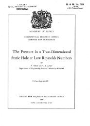
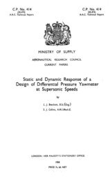
3.2. Details <strong>of</strong> Experiments.--3.2.1. <strong>Critical</strong> whirling speeds <strong>of</strong> the system <strong>and</strong> the natural<br />
vibrations, <strong>of</strong> the non-rotating system.--From measurements <strong>of</strong> whirl amplitudes <strong>and</strong> shaft<br />
rotational speeds, amplitude-frequency curves have been plotted (Fig. 2) showing the effect <strong>of</strong><br />
varying the inertias <strong>of</strong> the rotor. From these curves the critical whirling speeds for particular<br />
values <strong>of</strong> rotor inertia Were obtained <strong>and</strong> are compared in Fig. 3 with the calculated critical<br />
speeds <strong>of</strong> section 2.2.2.<br />
5
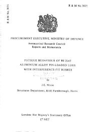
<strong>The</strong> lower natural frequency <strong>of</strong> the non-rotating system was measured for the same values <strong>of</strong><br />
rotor inertias used in the whirling experiments <strong>and</strong> is shown in Fig. 3 compared with the<br />
calculated frequencies <strong>of</strong> section 2.2.1.<br />
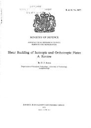
<strong>The</strong> deflection forms <strong>of</strong> the shaft when statically loaded at the rotor end, when vibrating<br />
transversely (non-rotating system) <strong>and</strong> when whirling were recorded <strong>and</strong> are compared in Fig. 4.<br />
It was not practicable to record the three deflection forms at the same tip amplitudes <strong>and</strong> for<br />
the purpose <strong>of</strong> comparison the measured forms were adjusted accordingly. <strong>The</strong> vibrating <strong>and</strong><br />
whirling deflection forms were recorded with maximum possible rotor inertias.<br />
3.2.2. <strong>The</strong> natural vibrations <strong>of</strong> the rotating system.--For these investigations the rotor inertias<br />
were set at the maximum possible values (c = 0.0526 lb in. sec 2, a = 0.026 lb in. sec ~) <strong>and</strong><br />
the rotor was accurately balanced. <strong>The</strong> rotating shaft was excited bymeans <strong>of</strong> a motor-<br />
driven crank elastically coupled to the shaft. Although the excitation was in a lateral direction,<br />
because <strong>of</strong> the inertia coupling it was effective in exciting the circular vibrations. An inductance-<br />
type proximity pick-up was used to investigate the resonant frequencies <strong>of</strong> the shaft, the signal<br />
from the pick-ups being recorded from a cathode-ray tube by means <strong>of</strong> a continuous-film camera<br />
<strong>and</strong> the frequencies measured against a fifty-cycle timing trace.<br />
<strong>The</strong> frequencies <strong>of</strong> the natural vibrations <strong>of</strong> the rotating shaft were obtained at various speeds<br />
<strong>of</strong> shaft rotation by running the shaft at a particular speed <strong>and</strong> exciting it over the frequency<br />
range <strong>of</strong> the exciter ; the resonant frequencies were observed visually on a monitor cathode-ray<br />
tube <strong>and</strong> then recorded to give an exact frequency reading. <strong>The</strong> range <strong>of</strong> shaft speeds over<br />
which investigations were carried out was chosen to cover speeds from zero r.p.m, to a value<br />
well above the critical whirling speed <strong>of</strong> the shaft. <strong>The</strong> results <strong>of</strong> these experiments are shown<br />
plotted in Figs. 5 <strong>and</strong> 6.<br />
4. Discussion <strong>of</strong> the Results.--4.1. <strong>The</strong> <strong>Critical</strong> <strong>Whirling</strong> <strong>Speeds</strong> <strong>of</strong> the System <strong>and</strong> the <strong>Natural</strong><br />
<strong>Vibrations</strong> <strong>of</strong> the Non-rotating System.--From Fig. 3 it is seen that the calculated values <strong>of</strong><br />
critical whirling speeds agree closely with those measured, but there is some discrepancy between<br />
measured <strong>and</strong> calculated natural frequencies <strong>of</strong> the non-rotating system, the difference being<br />
approximately 10 per cent over the range <strong>of</strong> rotor inertias investigated. This confirms the<br />
results <strong>of</strong> previous experiments on this rig 2. It is considered that the outrigger bearing imposes<br />
an extra constraint on the non-rotating system when vibrating transversely which is not present<br />
when the shaft is whirling thus changing the mode <strong>of</strong> vibration <strong>and</strong> increasing the natural<br />
frequency.<br />
<strong>The</strong> deflection forms <strong>of</strong> Fig. 4 show clearly the effect <strong>of</strong> the inertia couples arising from the<br />
appreciab'le inertia <strong>of</strong> the rotor. <strong>The</strong>oretically when the shaft is vibrating transversely the<br />
inertia couple will act in phase with the displacement <strong>of</strong> the shaft <strong>and</strong> have the same effect on<br />
the system as an increase in the flexibility coefficient Y11, i.e., reducing the natural frequency.<br />
This is shown in Fig. 4 by the increased curvature <strong>of</strong> the transverse vibration form compared<br />
with the static deflection form. When the shaft whirls the inertia couple theoretically acts in<br />
opposite phase to the displacement <strong>of</strong> the shaft thereby increasing the critical whirling speed :<br />
again this is shown in Fig. 4 by the decrease in curvature <strong>of</strong> the whirl deflection form, compared<br />
with the static form.<br />
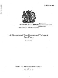
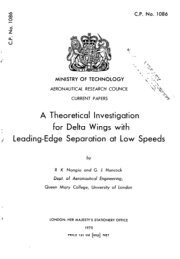
4.2. <strong>The</strong> <strong>Natural</strong> <strong>Vibrations</strong> <strong>of</strong> the Rotating System.--Figs. 5 <strong>and</strong> 6 show the measured natural<br />
frequencies <strong>of</strong> the rotating shaft.<br />
In Fig. 5 the measured frequencies have been plotted as they actually appeared, i.e., as definite<br />
frequencies at particular shaft rotational speeds, either in a forward or reverse sense with respect<br />
to the direction <strong>of</strong> rotation <strong>of</strong> the shaft. At ~ ----- 0 there are the two natural frequencies<br />
appropriate to the non-rotating system (see section 2.1.3). When the system is rotating, four<br />
frequencies are obtained in divergent pairs from the original two. <strong>The</strong> theoretical explanation<br />
<strong>of</strong> this phenomenon may be obtained from equation (14) (section 2.1.9.) which gives the frequencies<br />
<strong>of</strong> the free vibrations (~o) for any rotational speed (~). When ~ is zero there are four roots<br />
6
<strong>of</strong> equation (14) given by ~o = :t: c¢ <strong>and</strong> co = 4- ), : the negative roots <strong>of</strong> ~o correspond to the<br />
reverse whirls <strong>and</strong> the positive roots correspond to forward whirls. When the shaft is rotating<br />
the roots <strong>of</strong> equation (14) are no longer symmetrical, the negative roots decrease in frequency<br />
with increase <strong>of</strong> shaft speed <strong>and</strong> the positive roots increase in frequency, the negative roots<br />
are asymptotic to o~ = 0 <strong>and</strong> co = -- ,~/(611/mA) respectively <strong>and</strong> the positive roots are asymp-<br />
totic to ~o = + ~/(¢~/mA) <strong>and</strong> co = c(~?/a) respectively.<br />
In Fig. 6 the natural frequencies <strong>of</strong> Fig. 5 are plotted algebraically, positive <strong>and</strong> negative<br />
appropriate to forward <strong>and</strong> reverse motions respectively. Three sets <strong>of</strong> results have been<br />
plotted (co against s~), two calculated (one assuming rigid rotor arms <strong>and</strong> one allowing for<br />
flexibility in the rotor arms) <strong>and</strong> a set <strong>of</strong> measured results obtained by exciting the rotating<br />
system. It is seen that the lower frequencies are not appreciably affected by the flexibility<br />
<strong>of</strong> the rotor arms; the effect on the critical whirling speed <strong>of</strong> introducing arm flexibility into<br />
the calculations was found to be <strong>of</strong> the order <strong>of</strong> 1 per cent. However, the higher frequencies<br />
are affected to a greater degree, which is to be expected as the natural frequency <strong>of</strong> the rotor<br />
arms, was 58 c.p.s, <strong>and</strong> the measured value <strong>of</strong> y was 60 c.p.s. <strong>The</strong> calculated roots <strong>of</strong> the negative<br />
frequency originating in -- ~, are higher than those measured when the flexibility <strong>of</strong> the rotor<br />
arms is ignored, whereas on correcting for this flexibility the frequencies obtained are lower<br />
than those measured although the discrepancy between theory <strong>and</strong> experiment is less than in<br />
the latter case. In the case <strong>of</strong> the root originating in + y again the correction for rotor arm<br />
flexibility is too-great for the lower rotational shaft speeds but as the shaft speed increases the<br />
two curves <strong>of</strong> calculated <strong>and</strong> measured results quickly converge as the frequency <strong>of</strong> the circular<br />
vibration becomes appreciably greater than the natural frequencies <strong>of</strong> the rotor arms.<br />
5. Conclusions.--<strong>The</strong> experiments described show that, providing the constraints in a system<br />
are known precisely, it is possible to predict accurately the critical whirling speeds <strong>and</strong> the<br />
natural frequencies <strong>of</strong> the rotating system for a rotor <strong>of</strong> appreciable moment <strong>of</strong> inertia. <strong>The</strong><br />
allowance for flexibility <strong>of</strong> the rotor arms increases the accuracy <strong>of</strong> the calculations, especially<br />
when the frequencies are appreciably different from the natural non-rotary frequencies. <strong>The</strong><br />
method has the additional advantage that it is easily applied to the basic theory since only a<br />
change in the flexibility coefficient ¢~1 is required.<br />
<strong>The</strong> self-aligning outrigger bearing used in the experiments is shown to operate satisfactorily<br />
when the shaft is whirling, though the restraint on bending increases the natural frequency <strong>of</strong><br />
vibration when the shaft is not rotating.<br />
6. Further Developments.--<strong>The</strong> effect <strong>of</strong> bearings on tile critical whirling speeds <strong>of</strong> shaft<br />
systems, having regard to the constraints imposed on the system, <strong>and</strong> also the nature <strong>of</strong> the<br />
support given to a system when plain bearings are used, forms an important aspect in design<br />
calculations. A programme <strong>of</strong> tests on a large model rig is at present being carried out at<br />
Royal Aircraft Establishment to investigate the constraints in plain bearings <strong>of</strong> different lengths<br />
<strong>and</strong> clearance. Where possible, measurements are being taken <strong>of</strong> similar constraints in full-<br />
scale test rigs <strong>and</strong> aircraft power plant installations.<br />
No. AUthor<br />
1 E. Downham . . . . . . . .<br />
2 E. Downham . . . . . . . .<br />
3 J. Morris . . . . . . . . . .<br />
4 J. Morris . . . . . . . . . .<br />
5 H.H. Jeffcott . . . . . . . .<br />
REFERENCES<br />
Title, etc.<br />
<strong>The</strong> Experimental Approach to the Problems <strong>of</strong> Shaft <strong>Whirling</strong>.<br />
C.P.55. June, 1950.<br />
Some Preliminary Model Experiments on the <strong>Whirling</strong> <strong>of</strong> Shafts.<br />
R. & M. 2768. June, 1950.<br />
<strong>The</strong> Escalator Method in Engineering Vibration Problems. Chapman<br />
<strong>and</strong> Hall. 1947.<br />
<strong>The</strong> Strength <strong>of</strong> Shafts in Vibration. Crosby, Lockwood. 1929.<br />
<strong>The</strong> Lateral Vibration <strong>of</strong> Loaded Shafts in the Neighbourhood <strong>of</strong> a<br />
<strong>Whirling</strong> Speed. <strong>The</strong> Effect <strong>of</strong> Want <strong>of</strong> Balance. Phil. Mag.<br />
Vol. xxxvlI, pp. 304 to 314. March, 1919.
APPENDIX I<br />
<strong>The</strong> Calculation <strong>of</strong> the Flexibility Coefficients Yn¢n <strong>and</strong> zn<br />
<strong>The</strong> flexibility coefficients are best calculated by means <strong>of</strong> the energy method.<br />
"~ Z, >-<br />
o 2. P w<br />
SPRING ~<br />
STIFFNESS<br />
S' I b./in.<br />
<strong>The</strong> installation to be considered consists <strong>of</strong> a cantilever shaft 01 carrying a load W at 1 <strong>and</strong><br />
supported by a flexible prop at point 2. A couple C is assumed to act about point 1.<br />
Let P be the force exerted by the flexible prop.<br />
Let S be stiffness (lb/in.) <strong>of</strong> the prop.<br />
Let M02 be the bending moment at any section <strong>of</strong> the shaft between 0 <strong>and</strong> 2 distance x from 0.<br />
Let M12 be the bending moment at any section <strong>of</strong> the shaft between 1 <strong>and</strong> 2 distance x from 0.<br />
<strong>The</strong>n Mo2 = W(l -- x) + C -- P(a -- x)<br />
<strong>and</strong> M12 -~ W(1- x) + C.<br />
Between 0 <strong>and</strong><br />
At point 2,<br />
<strong>The</strong>refore<br />
El d~Y<br />
dx 2<br />
E1 dy<br />
dx<br />
Ely<br />
2<br />
-- Mo2= W(l-- x) + C-- P(a-- x)<br />
y ----y~, P = Sy~, x = a.<br />
Ely2 = W + ~-- Sy~<br />
<strong>The</strong>refore I + -~-j y= = W + ~-.<br />
2}<br />
For the actual system a = 10 in., 1 = 12 in., E1 = 5446 lb in. s, S = 82.89 lb/in.<br />
w(600- 167) + 50c<br />
<strong>The</strong>refore Y~ ----- 5446 + 10952 : 0-0264W + 0-00305C.<br />
<strong>The</strong>refore P = Sy2 = 0.8683W + 0. 1003C.<br />
8
<strong>The</strong> work done in bending the shaft is given by<br />
V -- 1 Mo2~dx -J- M122dx + P<br />
2EI o ~ 2Y~<br />
= ½[0-0367W ~ + O.OI050WC,::,+ 0.0013C ~] . . . . .<br />
Let Yn be the linear deflection at 1 due to unit load at 1<br />
zn be the linear deflection at 1 due to unit couple at 1<br />
= angular deflection at 1 due to unit load at 1<br />
¢n be the angular deflection at 1 due to unit couple at 1.<br />
<strong>The</strong>n due to the load W <strong>and</strong> couple C, the linear deflection at point 1<br />
= Wy l + Cz11.<br />
Angular deflection at point 1 : WZ~ + CCn ......<br />
<strong>and</strong> the work done by couple C <strong>and</strong> load W ,~ ,<br />
= -}[W~yn'+ 2WCzi-~ + C~¢n]. ' . . . . . . . .<br />
Equating the expressions on the right-h<strong>and</strong> sides <strong>of</strong> equations (1) <strong>and</strong> (2) gives<br />
½[0.0367W ~ + O:OI050WC + 0.0013C ~]<br />
1 2 = ~[Wyn + 2WCz~ + C~¢n]<br />
whence Yn = 0.0367 in./lb<br />
zn = O" 00525 in./lb<br />
<strong>and</strong> ¢n = 0"0013 radn/lb in.<br />
Effective length <strong>of</strong> shaft<br />
APPENDIX II<br />
Dimensional Details <strong>of</strong> Model Rig<br />
Distance <strong>of</strong> outrigger bearing from the' fixed end <strong>of</strong> the shaft<br />
Equivalent weight <strong>of</strong> shaft<br />
Weight <strong>of</strong> rotor ~'<br />
Hence equivalent end load<br />
Measured spring rate <strong>of</strong> outrigger bearing support<br />
Measured stiffness <strong>of</strong> shaft alone<br />
Measured stiffness <strong>of</strong> shaft <strong>and</strong> outrigger bearing support combined<br />
<strong>The</strong> deflection coefficients, calculated in Appendix II, are :--<br />
Yll = 0" 0367 in./lb<br />
411 = 0"0013 radn/lb in.<br />
z11 = O. 00525 in./lb in.<br />
From measurements taken on the rotor<br />
Ua,/la ~ = 0' 00033.<br />
9<br />
12 in.<br />
10 in.<br />
O. 0443 lb<br />
O. 888 lb<br />
O. 9323 lb<br />
32.89 lb/in.<br />
9.47 lb/in.<br />
27.3 lb/in.<br />
(1)<br />
(2)
1<br />
0 . ~ _ _<br />
0"~.<br />
OI<br />
0<br />
0<br />
~--9;c<br />
/ °,..4 x<br />
/___× _',.:~ ,. ~<br />
9( *X¢,'<br />
B~ / /<br />
2V.27,'<br />
I<br />
0 (c-A): t.ao Lt} ins ~<br />
' ~ (9 ¢.'~,)" ~.~o ~.E~ iNS ~<br />
, ~ ® t-A)- 5.515 LB. i~S ~<br />
, A (~ (C-A)- 7-E,3 LB IN~ ~<br />
FIG. 2.<br />
• .:. (~ (:-A)- I0.~0 LB. IN5 ~<br />
I<br />
CRITLCAL SPEED 17.7 RRS.<br />
17-6 ,,<br />
18.1<br />
• IB.45 ,,<br />
15'85 -<br />
l<br />
I0 15 20 ~5<br />
~HAFT SPEEO- ~P5<br />
FIG. 1. <strong>The</strong> whirling condition.<br />
<strong>The</strong> effect <strong>of</strong> rotor inertia on the critical whirling speed <strong>of</strong> a rotating shaft.<br />
10<br />
i<br />
30
E<br />
~3<br />
z N<br />
g~<br />
N"<br />
FIG. 4.<br />
IZ<br />
IO<br />
0 J4<br />
MAiM DRIVIN~<br />
5H~FT<br />
FIG. 3.<br />
N kT U~AL~ ~ ~E~~<br />
NATURAL F~EQUENCY<br />
15 ~G<br />
17 16<br />
FI~EQUENCY - C.P 5<br />
CRITICAL SPEED /<br />
(CALCULATE V<br />
<strong>The</strong> effect <strong>of</strong> rotor inertia on the natural vibrations <strong>of</strong> the non-rotating system<br />
<strong>and</strong> on the critical whirling speed.<br />
t , 5"r.kT[C DEFL£CT[ON FORM<br />
e ® WHI~LIN5<br />
c3 TRANSVERSE VlS~ATIOt~ •<br />
/ /<br />
0 { ~ ~ 4 5 ~ 7 8 -~ IO II I~<br />
DIST,~NCE FI~OM POINT OF kTTACHMENT TO MAtN D~,tVING 5HAFT (INS)<br />
Comparison between deflection forms <strong>of</strong> the non-rotating system when loaded statically at the rotor <strong>and</strong><br />
vibrating naturally <strong>and</strong> <strong>of</strong> the rotating system when whirling.<br />
11<br />
<br />
5PEE~<br />
RO<br />
C
FIG. 6.<br />
I CALCUL~'~ED ~RV~ ASSUMING |~ ,~<br />
" ~,B~ ,~.~ / . . . .<br />
!<br />
//'<br />
, I/!'. !l!<br />
II/ II<br />
~ll II<br />
i i jl # [ [ i<br />
\\<br />
• t<br />
i i i<br />
• . I Iilt<br />
-80 . -GO_.y -40 - I-~0_<br />
o<br />
o2 -<br />
I<br />
70~<br />
60t<br />
~ 401<br />
h:,<br />
t:3<br />
501<br />
~301<br />
0<br />
g<br />
g l CRITICAL<br />
WIIIRLIN~<br />
SPEED ' /<br />
I01 /<br />
'£d3 13N3Qb3~<br />
t /<br />
! _~'! !<br />
_t<br />
~ o<br />
• o .~ o<br />
/ /<br />
' ' i" /<br />
/ '//"<br />
/- //.<br />
/'] -<br />
xl / //<br />
/ , I<br />
i i<br />
0 +,~ ~0 +j 40 + ~ ~0 80 I00 I~0 14'Q<br />
F~EQUENCY OF NATUJ~,L VIBRATION5 '~'" C.P.<br />
<strong>The</strong> natural vibrations <strong>of</strong> a rotating shaft carrying a rotor <strong>of</strong> appreciable moments <strong>of</strong> inertia (measured<br />
<strong>and</strong> calculated).<br />
12<br />
=:<br />
><br />
i<br />
~o.~<br />
-o<br />
O3<br />
b~O
Four Arm<br />
Rotor<br />
B<br />
-;":~: ~ '<br />
Adjustable<br />
Weights<br />
J4300 Wt.17/680 K9 9/54 D&Co. 34/263<br />
Flexible<br />
Bearing<br />
FIG. 7. Details <strong>of</strong> the model shaft rotor system.<br />
13<br />
Main Driving<br />
Shaft<br />
°<br />
<strong>Whirling</strong><br />
Shaft<br />
PRINTED IN GREAT BRITAIN
ANNUAL<br />
Publications <strong>of</strong> the<br />
Aeronautical Research Council<br />
TECHNICAL REPORTS OF THE AERONAUTICAL RESEARCH COUNCIL<br />
(BOUND VOLUMES)<br />
R. & M. No. 2854<br />
1936 Vol. I. Aerodynamics General, Performance, Airscrews, Flutter <strong>and</strong> Spinning. 4os. (4IS. Id).<br />
Vol. II. Stability <strong>and</strong> Control, Structures, Seaplanes, Engines, etc. 5os. (5IS. Id.)<br />
1937 Vol. I. Aerodynamics General, Performance, Airscrews, Flutter <strong>and</strong> Spinning. 4os. (4IS. id.)<br />
Vol. II. Stability <strong>and</strong> Control, Structures, Seaplanes, Engines, etc. 6os. (6is. I&)<br />
1938 Vol. I. Aerodynamics General, Performance, Airscrews. 5os. (Sis, Id.)<br />
Vol. II. Stability <strong>and</strong> Control, Flutter, Structures, Seaplanes, Wind Tunnels, Materials. 3os. (3 is. id.)<br />
1939 Vol. I. Aerodynamics General, Performance, Airscrews, Engines. 5os. (5 is. id.)<br />
Vol. II. Stability <strong>and</strong> Control, Flutter <strong>and</strong> Vibration, Instruments,<br />
63 s. (64 s. 2d.)<br />
Structures, Seaplanes, etc.<br />
194o Aero <strong>and</strong> Hydrodynamics, Aer<strong>of</strong>oils, Airscrews, Engines, Flutter, Icing, Stability <strong>and</strong> Control,<br />
Structures, <strong>and</strong> a miscellaneous section. 5os. (5IS. id.)<br />
1941 Aero <strong>and</strong> Hydrodynamics, Aer<strong>of</strong>oils, Airscrews, Engines, Flutter, Stability <strong>and</strong> Control, Structures.<br />
63 s. (64 s. 2d.)<br />
1942 Vol. I. Aero <strong>and</strong> Hydrodynamics, Aer<strong>of</strong>oils, Airscrews, Engines. 75s. (76s. 3d.)<br />
Vol~ II. Noise, Parachutes, Stability <strong>and</strong> Control, Structures, Vibration, Wind Tunnels.<br />
(48s. 7d.)<br />
1943 Vol. I. Aerodynamics, Aer<strong>of</strong>oils, Airscrews, 8os. (8is. 4d.)<br />
47 s. 6d.<br />
Vol. n. Engines, Fhltter, Materials, Parachutes, Performance, Stability <strong>and</strong> Control, Structures.<br />
9os. (9IS. 6d.)<br />
1944 Vol. I. Aero <strong>and</strong> Hydrodynamics, Aer<strong>of</strong>oils, Aircraft, Airscrews, Controls. 84 s. (85s. 8d.)<br />
Vol. II. Flutter <strong>and</strong> Vibration, Materials, Miscellaneous , Navigation, Parachutes, Performance,<br />
Plates, <strong>and</strong> Panels, Stability, Structures, Test Equipment, Wind Tunnels. 84 s. (85s. 8d.)<br />
ANNUAL REPORTS OF THE AERONAUTICAL RESEARCH COUNCIL--<br />
1933-34 is. 6d. (is. 8d.) 1937 2s. (2s. 2d.)<br />
1934-35 IS. 6d. (IS. 8d.) 1938 IS. 6d. (IS. 8d.)<br />
April I, 1935 to Dec. 31, I936. 4 s. (4 s. 4 d.) 1939-48 3 s. (3s. 2d.)<br />
INDEX TO ALL REPORTS AND MEMORANDA PUBLISHED IN THE ANNUAL TECHNICAL<br />
REPORTS, AND SEPARATELY--<br />
April, 195o . . . . R. & M. No. 2600. 2s. 6d. (2s. 7½d.)<br />
AUTHOR INDEX TO ALL REPORTS AND MEMORANDA OF THE AERONAUTICAL RESEARCH<br />
COUNCIL--<br />
19o9-1949 . . . . . R.& M. No. 2570. ISS. (ISS. 3d.)<br />
INDEXES TO THE TECHNICAL REPORTS OF THE AERONAUTICAL RESEARCH COUNCIL---<br />
December I, 1936 -- June 30, 1939.<br />
July 1,1939 -- June 30, 1945.<br />
July i, 1945 -- June 30, 1946.<br />
July 1, 1946 -- December 31, 1946.<br />
January i, 1947 -- June 30, 1947.<br />
July, 1951 . . . .<br />
R. & M. No. 185o.<br />
R. & M. No. 195o.<br />
R. & M. No. 2050.<br />
,R. & M. No. 215o.<br />
R. & M. No. 2250;<br />
R. & M. No. 2350.<br />
Prices in brackets include 2hostage.<br />
Obtainable from<br />
HER MAJESTY'S STATIONERY OFFICE<br />
is. 3d. (is. 4½d.)<br />
is. (is. I½d.)<br />
is. (is. i½d.)<br />
is. 3d. (is. 4½d.)<br />
IS. 3 d. (is. 4½d.)<br />
IS. 9 d. (IS. Io½d.)<br />
York House, Kingsway, London W.C.2 ; 423 Oxford Street, London W.1 (Post Orders : P.O. Box No. 569, London S.E.1) ;<br />
13A Castle Street, Edinburgh 2 ; 39 King Street, l~lanchester 2 ; 2 Edmund Street, BJrmJngham 3 : 1 St..Andrew's<br />
Crescent, Cardiff ; Tower Lane, Bristol I ; 80 Chichester Street, Belfast OR THROUGH ANY BOOKSELLER<br />
s.o. Code NO. 23-2854<br />
R. & M. No. 2854