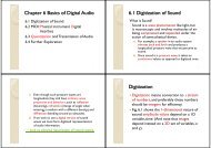
2.1 Multimedia Authoring g – Multimedia Authoring Metaphors g p
2.1 Multimedia Authoring g – Multimedia Authoring Metaphors g p
2.1 Multimedia Authoring g – Multimedia Authoring Metaphors g p

Create successful ePaper yourself
Turn your PDF publications into a flip-book with our unique Google optimized e-Paper software.
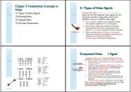
Chapter 2 <strong>Multimedia</strong> <strong>Authoring</strong> and<br />
Tools<br />
<strong>2.1</strong> <strong>Multimedia</strong> <strong>Authoring</strong><br />
2.2 Some Useful Editing and <strong>Authoring</strong> Tools<br />
2.3 VRML<br />
24Further 2.4 Further Exploration<br />
<strong>–</strong> <strong>Multimedia</strong> <strong>Authoring</strong> g <strong>Metaphors</strong> p<br />
• Scripting Language Metaphor: use a special<br />
language to enable interactivity (buttons,<br />
mouse, , etc.), ), and to allow conditionals, ,<br />
jumps, loops, functions/macros etc. E.g., a<br />
small Toolbook program is as below:<br />
1<br />
3<br />
<strong>2.1</strong> <strong>Multimedia</strong> <strong>Authoring</strong> g<br />
<strong>Multimedia</strong> authoring: creation of multimedia<br />
productions productions, sometimes called "movies" movies or<br />
"presentations".<br />
◦ we are mostly interested in interactive applications applications.<br />
◦ For practicality, we also have a look at still‐image<br />
editors such as Adobe Photoshop, Photoshop and simple video<br />
editors such as Adobe Premiere.<br />
In this section, we take a look at:<br />
◦ <strong>Multimedia</strong> <strong>Authoring</strong> <strong>Metaphors</strong><br />
◦ <strong>Multimedia</strong> Production<br />
◦ <strong>Multimedia</strong> Presentation<br />
◦ AAutomatic i A<strong>Authoring</strong> h i<br />
Slide Show Metaphor: A linear<br />
presentation i bby df default, l although lh htools l<br />
exist to perform jumps in slide shows.<br />
Hierarchical Metaphor: User‐controllable<br />
elements are organized into a tree<br />
structure —often used in menu‐driven<br />
applications.<br />
Iconic/Flow‐control Metaphor: Graphical<br />
iicons are available il bl iin a toolbox, t lb and d<br />
authoring proceeds by creating a flow<br />
chart h with ihiicons attached hd(Fi (Fig. 21) <strong>2.1</strong>):<br />
2<br />
4
Fig. <strong>2.1</strong>: Authorware flowchart<br />
• Card/Scripting Metaphor: Uses a simple<br />
index‐card structure —easy route to<br />
producing p gapplications pp that use hypertext yp<br />
or hypermedia; used in schools.<br />
Fig. 2.3: Two Cards in a Hypermedia Stack<br />
5<br />
7<br />
Frames Metaphor: Like Iconic/Flow‐control<br />
Metaphor; however links between icons are more<br />
conceptual, rather than representing the actual<br />
flow of the program (Fig. 2.2):<br />
Cast/Score/Scripting Metaphor:<br />
Fig. 2.2: Quest Frame<br />
6<br />
◦ Time is shown horizontally; like a spreadsheet:<br />
rows, or tracks, represent instantiations of<br />
characters in a multimedia production.<br />
◦ <strong>Multimedia</strong> elements are drawn from a cast of<br />
characters, and scripts are basically event‐<br />
procedures or procedures that are triggered by<br />
timer events.<br />
◦ Director, by y Macromedia, is the chief example p<br />
of this metaphor. Director uses the Lingo<br />
scripting language, an object‐oriented event‐<br />
driven language.<br />
8
<strong>–</strong> <strong>Multimedia</strong> Presentation<br />
Graphics Styles: Human visual dynamics<br />
impact how presentations must be<br />
constructed.<br />
a) Color principles and guidelines: Some color<br />
schemes and art styles y are best combined with a<br />
certain theme or style. A general hint is to not<br />
use too many colors, as this can be distracting.<br />
b) Fonts: For effective visual communication in a<br />
presentation, it is best to use large fonts (i.e., 18<br />
to 36 points), and no more than 6 to 8 lines per<br />
screen (fewer ( than on this screen!). ) Fig. g 2.4<br />
shows a comparison of two screen projections:<br />
9<br />
A color contrast program: If the text color is<br />
some triple (R,G,B), (R G B) a legible color for the<br />
background is that color subtracted from the<br />
maximum (here ( assuming g max=1): )<br />
(R, G, B) (1 − R, 1 − G, 1 − B) (<strong>2.1</strong>)<br />
◦ Some color combinations are more pleasing than<br />
others; e.g., a pink background and forest green<br />
foreground, or a green background and mauve<br />
foreground. Fig. 2.5 shows a small VB program<br />
(textcolor.exe) in operation:<br />
→ Li Link k to TTextColor C l src.zip i<br />
→ Link to textcolor.exe<br />
11<br />
Fig 2.4: Colors and fonts [from Ron Vetter].<br />
Fig. 2.5: Program to investigate colors and<br />
readability.<br />
10<br />
12
<strong>–</strong> Fig. 2.6, shows a "color wheel", with opposite colors equal to<br />
(1‐R,1‐G,1‐B):<br />
Fig. 2.6: Color l wheel h l<br />
We can overlay the sprite on a colored background<br />
BB, as in Fig Fig. 28(a) 2.8 (a) by first ANDing B and M, M and<br />
then ORing the result with S, with final result as in<br />
Fig. 2.8 (e).<br />
Fig. 2.8: Sprite animation: (a): Background B.(b): Mask M.(c): B AND<br />
M.(d): Sprite S.(e): B AND M OR S<br />
13<br />
15<br />
Sprite p Animation<br />
The basic idea: Suppose we have an animation figure, as in Fig.<br />
2.7 (a). Now create a 1‐bit mask M, as in Fig. 2.7 (b), black on<br />
white, and accompanying sprite S, asinFig.2.7 (c).<br />
Fig Fig. 27:Sprite 2.7: Sprite creation: Original Original, mask image MM, and sprite S<br />
("Duke" figure courtesy of Sun Microsystems.)<br />
Video Transitions<br />
• Video transitions: to signal "scene changes".<br />
• Many different types of transitions:<br />
<strong>–</strong> Cut: an abrupt change of image contents<br />
formed by abutting two video frames<br />
consecutively. This is the simplest and most<br />
frequently used video transition.<br />
14<br />
16
Wipe: a replacement of the pixels in a region<br />
of the viewport with those from another<br />
video. Wipes can be left‐to‐right, right‐to‐left,<br />
vertical, , horizontal, , like an iris opening, p g, swept p<br />
out like the hands of a clock, etc.<br />
Di Dissolve: l replaces l every pixel i lwith iha mixture i<br />
over time of the two videos, gradually<br />
replacing the first by the second. second Most<br />
dissolves can be classified as two types: cross<br />
dissolve and dither dissolve.<br />
Type yp II: Dither Dissolve<br />
• Determined by α(t), increasingly more and<br />
more pixels in video A will abruptly (instead<br />
of gradually g yas in Type yp I) ) change g to video B.<br />
17<br />
19<br />
Type yp I: Cross Dissolve<br />
• Every pixel is affected gradually. It can be<br />
defined by:<br />
where A and B are the color 3‐vectors for<br />
video A and video B. Here, α(t) is a<br />
transition function function, which is often linear:<br />
• Fade‐in and fade‐out are special types of<br />
Type I dissolve: video A or B is black (or<br />
white). ) Wipes p are special p forms of Type yp II<br />
dissolve in which changing pixels follow a<br />
particular geometric pattern pattern.<br />
• Build‐your‐own‐transition: Suppose we<br />
wish to build a special type of wipe which<br />
slides one video out while another video<br />
slides in to replace it: a slide (or push).<br />
18<br />
20
Unlike a wipe, we want each video frame not be held in<br />
place, but instead move progressively farther into (out<br />
of) the viewport.<br />
Suppose we wish to slide VideoL in from the left, and<br />
push out VideoR. Figure 2.9 shows this process:<br />
Fig. g 2.9: (a): () VideoL. L (b): ( ) VideoR. R (c): () Video L sliding g into<br />
place and pushing out VideoR. Suppose that we have determined that pixels<br />
should h ldcome ffrom Vid VideoL. Th Then the th x‐position iti<br />
xL in the unmoving video should be xL = x<br />
+(x +(xmax − x xT ) ), where x is the position we are<br />
trying to fill in the viewport, xT is the position<br />
in the viewport that the transition boundary<br />
has reached, and xmax is the maximum pixel<br />
position for any frame frame.<br />
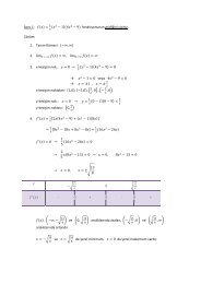
From Fig. <strong>2.1</strong>0(b), we can calculate the<br />
position ii xL iin Vid VideoL's ' coordinate di system as<br />
the sum of the distance x, in the viewport,<br />
plus l the th diff difference xmax − xT .<br />
21<br />
23<br />
Slide Transition (Cont'd) ( )<br />
As time goes by, the horizontal location xT for<br />
the transition boundary moves across the<br />
viewport from xT =0 at t =0 to xT = xmax at t =<br />
tmax. Therefore, for a transition that is linear<br />
in time, xT =(t/tmax)xmax.<br />
( )<br />
So for any time t the situation is as shown in<br />
Fig Fig. <strong>2.1</strong>0 210(a) (a). Let's assume that dependence on<br />
y is implicit since we use the same y as in the<br />
source video. id Then Th for f the h red d channel h l( (and d<br />
similarly for the green and blue), R = R(x, t).<br />
Fig. <strong>2.1</strong>0: (a): Geometry of Video L pushing out Video R. (b): Calculating<br />
L R<br />
position in Video L from where pixels are copied to the viewport.<br />
22<br />
24
Slide Transition (Cont'd) ( )<br />
Substituting the fact that the transition moves<br />
li linearly l with ith ti time, xT = xmax(t/t (t/t max), ) a<br />
pseudocode solution in shown in Fig. <strong>2.1</strong>1.<br />
Fig. <strong>2.1</strong>1: Pseudocode for slide video transition<br />
25<br />
4. Delivery Methods:<br />
Not everyone has rewriteable DVD drives, as<br />
yet.<br />
CD‐ROMs: may be not enough storage to hold<br />
a multimedia presentation presentation. As well well, access<br />
time for CD‐ROM drives is longer than for<br />
hard‐disk hard disk drives.<br />
Electronic delivery is an option, but depends<br />
on network bandwidth at the user side (and<br />
at server). A streaming option may be<br />
available available, depending on the presentation<br />
presentation.<br />
27<br />
Some Technical Design g Issues<br />
Computer Platform: Much software is ostensibly<br />
"portable" portable but cross cross‐platform platform software relies on<br />
run‐time modules which may not work well across<br />
systems.<br />
Video format and resolution: The most popular<br />
video formats — NTSC NTSC, PAL, PAL and SECAM SECAM— are not<br />
compatible, so a conversion is required before a<br />
video can be played on a player supporting a<br />
different format.<br />
Memory y and Disk Space p Requirement: q At least 128<br />
MB of RAM and 20 GB of hard‐disk space should be<br />
available for acceptable performance and storage<br />
ffor multimedia l d programs.<br />
<strong>–</strong> Automatic <strong>Authoring</strong> g<br />
Hypermedia documents: Generally, three<br />
steps:<br />
1. Capture p of media: From text or using g an<br />
audio digitizer or video frame‐grabber; is<br />
highly developed and well automated.<br />
2. <strong>Authoring</strong>: How best to structure the data in<br />
order to support multiple views of the<br />
available data, rather than a single, static view.<br />
3. Publication: i.e. Presentation, is the objective<br />
of the multimedia tools we have been<br />
considering.<br />
26<br />
28
EExternalization li i versus li linearization: i i<br />
a) Fig. <strong>2.1</strong>2(a) shows the essential problem involved in<br />
communicating ideas without using a hypermedia<br />
mechanism.<br />
b) ) In contrast, , hyperlinks yp allow us the freedom to<br />
partially mimic the author's thought process (i.e.,<br />
externalization).<br />
c) Using Using, e.g., eg Microsoft Word Word, creates a hpertet hypertext<br />
version of a document by following the layout already<br />
set up in chapters, headings, and so on. But problems<br />
arise i when h we actually t ll need d tto automatically t ti ll extract t t<br />
semantic content and find links and anchors (even<br />
considering just text and not images etc.) Fig. <strong>2.1</strong>3<br />
di displays l the h problem. bl<br />
Fig. i 2<strong>2.1</strong>3: 3 Complex C l iinformation f i space [f [from David id Lowe]. ]<br />
Once a dataset becomes large we should employ<br />
database methods. The issues become focused on<br />
scalability (to a large dataset), maintainability, addition<br />
of material, and reusability.<br />
Fig. <strong>2.1</strong>2: Communication using hyperlinks [from David Lowe].<br />
29 30<br />
31<br />
Semi‐automatic migration g of hypertext yp<br />
• The structure of hyperlinks for text<br />
information is simple: "nodes"represent<br />
semantic information and these are<br />
anchors for links to other pages.<br />
Fig. <strong>2.1</strong>4: Nodes and anchors in hypertext [from David Lowe].<br />
32
Hyperimages yp g<br />
• We need an automated method to help us<br />
produce true hypermedia:<br />
Fig. <strong>2.1</strong>5: Structure of hypermedia [from David Lowe].<br />
2.2 Some Useful Editing and <strong>Authoring</strong><br />
Tools<br />
One needs real vehicles for showing understanding<br />
principles of and creating multimedia. multimedia And straight<br />
programming in C++ or Java is not always the best<br />
way of showing your knowledge and creativity.<br />
Some popular authoring tools include the following:<br />
◦ Ad Adobe b PPremiere i 6<br />
◦ Macromedia Director 8 and MX<br />
◦ Flash 5 and MX<br />
◦ Dreamweaver MX<br />
Hint for Studying This Section: Hands‐on work in a<br />
Lab environment, with reference to the text.<br />
33<br />
35<br />
Can manually delineate syntactic image<br />
elements by masking image areas areas. Fig Fig. <strong>2.1</strong>6 216<br />
shows a "hyperimage", with image areas<br />
identifed and automatically y linked to other<br />
parts of a document:<br />
Fig. <strong>2.1</strong>6: Hyperimage [from David Lowe].<br />
2.<strong>2.1</strong> Adobe Premiere<br />
2.2.2 Macromedia Director<br />
2.2.3 Macromedia Flash<br />
224Dreamweaver<br />
2.2.4 Dreamweaver<br />
Cakewalk Pro Audio<br />
34<br />
36
2.3 VRML (Virtual Reality Modelling<br />
Language)<br />
Overview<br />
VRML: conceived in the first international<br />
conference of the World Wide Web as a<br />
platform‐independent language that would be<br />
viewed on the Internet.<br />
Objective of VRML: capability to put colored<br />
objects into a 3D environment.<br />
VRML is an interpreted language; however it<br />
has been very influential since it was the first<br />
method available for displaying a 3D world on<br />
the World Wide Web. Web<br />
The last major revision of VRML was VRML 2.0,<br />
standardized by ISO as VRML97:<br />
◦ This revision added the ability to create an interactive<br />
world world. VRML 2.0, 20 also called "Moving Moving Worlds" Worlds , allows<br />
for animation and sound in an interactive virtual world.<br />
◦ New objects were added to make the creation of virtual<br />
worlds easier.<br />
◦ Java and Javascript p have been included in VRML to<br />
allow for interactive objects and user‐defined actions.<br />
◦ VRML 2.0 was a large change from VRML 1.0 and they<br />
are not compatible with each other. However,<br />
conversion utilities are available to convert VRML 1.0 to<br />
VRML 2.0 20automatically<br />
automatically.<br />
37<br />
39<br />
History y of VRML<br />
• VRML 1.0 was created in May of 1995, with<br />
a revision for clarification called VRML 1.0C<br />
in January y of 1996:<br />
<strong>–</strong> VRML is based on a subset of the file inventor<br />
format created by Silicon Graphics Inc Inc.<br />
<strong>–</strong> VRML 1.0 allowed for the creation of many<br />
simple 3D objects such as a cube and sphere<br />
as well as user‐defined polygons. Materials<br />
and textures can be specified for objects to<br />
make the objects more realistic.<br />
VRML Shapes p<br />
VRML contains basic geometric shapes that can be<br />
combined to create more complex objects. Fig. 2.28<br />
displays some of these shapes:<br />
Fig. 2.28: Basic VRML shapes.<br />
◦ Shape node is a generic node for all objects in VRML. VRML<br />
◦ Material node specifies the surface properties of an object.<br />
It can control what color the object is by specifying the red,<br />
green and d blue bl values l of f the th object. bj t<br />
38<br />
40
There are three kinds of texture nodes that<br />
can be used to map textures onto any object:<br />
1. ImageTexture: g The most common one that can<br />
take an external JPEG or PNG image file and map<br />
it onto the shape.<br />
2. MovieTexture: allows the mapping of a movie<br />
onto an object; can only use MPEG movies.<br />
3. PixelTexture: simply means creating an image to<br />
use with ImageTexture within VRML. VRML Fig Fig. 229 2.29<br />
displays a simple VRML scene from one viewpoint:<br />
Fig. 2.29: A simple VRML scene.<br />
41<br />
43<br />
VRML world<br />
Fig. 2.29 displays a simple VRML scene from<br />
one viewpoint: i i t<br />
→ Openable‐book VRML simple world!:<br />
→ Link to mmbook/examples/vrml.html.<br />
◦ Th The position iti of f a viewpoint i i tcan bbe specified ifi d with ith<br />
the position node and it can be rotated from the<br />
default view with the orientation node.<br />
◦ Also the camera's angle for its field of view can be<br />
changed from its default 0.78 radians, with the<br />
fieldOfView node.<br />
◦ Changing the field of view can create a telephoto<br />
effect.<br />
42<br />
Three types of lighting can be used in a VRML world:<br />
◦ DirectionalLight node shines a light across the whole world<br />
in a certain direction.<br />
◦ PointLight shines a light from all directions from a certain<br />
point in space.<br />
◦ SpotLight shines a light in a certain direction from apoint.<br />
◦ RenderMan: d rendering d i package k created d by b Pixar. i<br />
The background of the VRML world can also be<br />
specified using the Background node. node<br />
A Panorama node can map a texture to the sides of the<br />
world. A panorama p is mapped pp onto a large g cube<br />
surrounding the VRML world.<br />
44
Animation and Interactions<br />
The only method of animation in VRML is by<br />
tweening tweening‐ done by slowly changing an object that<br />
is specified in an interpolator node.<br />
Thi This node d will ill modify dif an object bj t over time, ti based b d<br />
on the six types of interpolators: color, coordinate,<br />
normal normal, orientation, orientation position, position and scalar. scalar<br />
(a) All interpolators have two nodes that must be<br />
specified: the key and keyValue.<br />
(b) The key consists of a list of two or more numbers<br />
starting g with 0 and ending g with 1, , defines how far<br />
along the animation is.<br />
(b) Each key element must be complemented with a<br />
keyValue element: defines what values should<br />
change. 45<br />
VRML Specifics p<br />
Some VRML Specifics:<br />
a) A VRML le is simply a text le with a ".wrl"<br />
extension.<br />
b) VRML97 needs d tto iinclude l d th the li line #VRML V2.0 V2 0<br />
UTF8 in the first line of the VRML le | tells the<br />
VRML client what version of VRML to use.<br />
c) VRML nodes are case sensitive and are usually<br />
built in a hierarchical manner.<br />
d) All Nodes begin with "{" and end with "}" and<br />
most can contain nodes inside of nodes.<br />
e) Special nodes called group nodes can cluster<br />
together multiple nodes and use the keyword<br />
"children" children followed by "[ [ ... ]" ] .<br />
47<br />
To time an animation, a TimeSensor node should be<br />
used:<br />
◦ TimeSensor has no physical form in the VRML world and just<br />
keeps time.<br />
◦ To notify an interpolator of a time change, a ROUTE is<br />
needed to connect two nodes together.<br />
◦ Most animation can be accomplished through the method of<br />
routing a TimeSensor to an interpolator node, and then the<br />
interpolator node to the object to be animated.<br />
TTwo categories i of f sensors can be b used d in i VRML to<br />
obtain input from a user:<br />
◦ Environment sensors: three kinds of environmental sensor<br />
nodes: VisibilitySensor, ProximitySensor, and Collision.<br />
◦ Pointing device sensors: touch sensor and drag sensors.<br />
f) Nodes can be named using DEF and be used again<br />
later by y using g the keyword y USE. This allows for the<br />
creation of complex objects using many simple<br />
objects.<br />
A simple i l VRML example l tto create t a box b in i VRML: VRML<br />
one can accomplish this by typing:<br />
Shape {<br />
Geometry Box{}<br />
}<br />
The Box defaults to a 2‐meter long cube in the<br />
center of f the h screen. Putting it into a Transform f<br />
node can move this box to a different part of the<br />
scene. We can also give the box a different color,<br />
such as red.<br />
46<br />
48
Transform { translation 0 10 0 children [<br />
Shape {<br />
Geometry y Box{} {}<br />
appearance Appearance {<br />
material Material {<br />
diffuseColor 1 0 0<br />
}<br />
}<br />
}<br />
]}<br />
49<br />
2.4 Further Exploration p<br />
→ Link to Further Exploration for Chapter 2.<br />
Good general g references for multimedia<br />
authoring are introductory books [3,1] and<br />
Chapters 5‐8 in [4].<br />
A link to the overall, and very useful, FAQ le<br />
for multimedia authoring is in the textbook<br />
website's bi ' "Further "F h EExploration" l i " section i for f<br />
Chapter 2.<br />
A link to a good FAQ collection for Director,<br />
plus a simple Director movie:<br />
→ Link to mmbook/examples/director.html.<br />
50