Bunn VLFP User Manual - The Coffee Bump
Bunn VLFP User Manual - The Coffee Bump
Bunn VLFP User Manual - The Coffee Bump

Create successful ePaper yourself
Turn your PDF publications into a flip-book with our unique Google optimized e-Paper software.
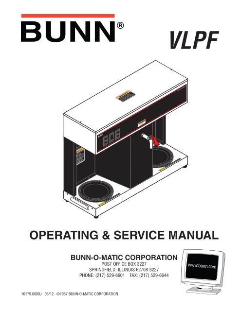
OPERATING & SERVICE MANUAL<br />
10179.0000J 05/12 ©1987 BUNN-O-MATIC CORPORATION<br />
BUNN-O-MATIC CORPORATION<br />
POST OFFICE BOX 3227<br />
SPRINGFIELD, ILLINOIS 62708-3227<br />
PHONE: (217) 529-6601 FAX: (217) 529-6644<br />
VLPF
BUNN-O-MATIC COMMERCIAL PRODUCT WARRANTY<br />
<strong>Bunn</strong>-O-Matic Corp. (“BUNN”) warrants equipment manufactured by it as follows:<br />
1) Airpots, thermal carafes, decanters, GPR servers, iced tea/coffee dispensers, MCP/MCA pod brewers thermal servers<br />
and <strong>The</strong>rmofresh servers (mechanical and digital)- 1 year parts and 1 year labor.<br />
2) All other equipment - 2 years parts and 1 year labor plus added warranties as specified below:<br />
a) Electronic circuit and/or control boards - parts and labor for 3 years.<br />
b) Compressors on refrigeration equipment - 5 years parts and 1 year labor.<br />
c) Grinding burrs on coffee grinding equipment to grind coffee to meet original factory screen sieve analysis - parts<br />
and labor for 4 years or 40,000 pounds of coffee, whichever comes first.<br />
<strong>The</strong>se warranty periods run from the date of installation BUNN warrants that the equipment manufactured by it will be<br />
commercially free of defects in material and workmanship existing at the time of manufacture and appearing within the<br />
applicable warranty period. This warranty does not apply to any equipment, component or part that was not manufactured<br />
by BUNN or that, in BUNN’s judgment, has been affected by misuse, neglect, alteration, improper installation or operation,<br />
improper maintenance or repair, non periodic cleaning and descaling, equipment failures related to poor water quality,<br />
damage or casualty. In addition, the warranty does not apply to replacement of items subject to normal use including but<br />
not limited to user replaceable parts such as seals and gaskets. This warranty is conditioned on the Buyer 1) giving BUNN<br />
prompt notice of any claim to be made under this warranty by telephone at (217) 529-6601 or by writing to Post Office<br />
Box 3227, Springfield, Illinois 62708-3227; 2) if requested by BUNN, shipping the defective equipment prepaid to an<br />
authorized BUNN service location; and 3) receiving prior authorization from BUNN that the defective equipment is under<br />
warranty.<br />
THE FOREGOING WARRANTY IS EXCLUSIVE AND IS IN LIEU OF ANY OTHER WARRANTY, WRITTEN OR ORAL, EX-<br />
PRESS OR IMPLIED, INCLUDING, BUT NOT LIMITED TO, ANY IMPLIED WARRANTY OF EITHER MERCHANTABILITY<br />
OR FITNESS FOR A PARTICULAR PURPOSE. <strong>The</strong> agents, dealers or employees of BUNN are not authorized to make<br />
modifications to this warranty or to make additional warranties that are binding on BUNN. Accordingly, statements by such<br />
individuals, whether oral or written, do not constitute warranties and should not be relied upon.<br />
If BUNN determines in its sole discretion that the equipment does not conform to the warranty, BUNN, at its exclusive option<br />
while the equipment is under warranty, shall either 1) provide at no charge replacement parts and/or labor (during the<br />
applicable parts and labor warranty periods specified above) to repair the defective components, provided that this repair<br />
is done by a BUNN Authorized Service Representative; or 2) shall replace the equipment or refund the purchase price for<br />
the equipment.<br />
THE BUYER’S REMEDY AGAINST BUNN FOR THE BREACH OF ANY OBLIGATION ARISING OUT OF THE SALE OF THIS<br />
EQUIPMENT, WHETHER DERIVED FROM WARRANTY OR OTHERWISE, SHALL BE LIMITED, AT BUNN’S SOLE OPTION<br />
AS SPECIFIED HEREIN, TO REPAIR, REPLACEMENT OR REFUND.<br />
In no event shall BUNN be liable for any other damage or loss, including, but not limited to, lost profits, lost sales, loss of<br />
use of equipment, claims of Buyer’s customers, cost of capital, cost of down time, cost of substitute equipment, facilities<br />
or services, or any other special, incidental or consequential damages.<br />
392, AutoPOD, AXIOM, BrewLOGIC, BrewMETER, Brew Better Not Bitter, BrewWISE, BrewWIZARD, BUNN Espress, BUNN<br />
Family Gourmet, BUNN Gourmet, BUNN Pour-O-Matic, BUNN, BUNN with the stylized red line, BUNNlink, <strong>Bunn</strong>-OMatic,<br />
<strong>Bunn</strong>-O-Matic, BUNNserve, BUNNSERVE with the stylized wrench design, Cool Froth, DBC, Dr. Brew stylized Dr. design,<br />
Dual, Easy Pour, EasyClear, EasyGard, FlavorGard, Gourmet Ice, Gourmet Juice, High Intensity, iMIX, Infusion Series, Intellisteam,<br />
My Café, Phase Brew, PowerLogic, Quality Beverage Equipment Worldwide, Respect Earth, Respect Earth with<br />
the stylized leaf and coffee cherry design, Safety-Fresh, savemycoffee.com, Scale-Pro, Silver Series, Single, Smart Funnel,<br />
Smart Hopper, SmartWAVE, Soft Heat, SplashGard, <strong>The</strong> Mark of Quality in Beverage Equipment Worldwide, <strong>The</strong>rmoFresh,<br />
Titan, trifecta, Velocity Brew, A Partner You Can Count On, Air Brew, Air Infusion, Beverage Bar Creator, Beverage Profit<br />
Calculator, Brew better, not bitter., BUNNSource, <strong>Coffee</strong> At Its Best, Cyclonic Heating System, Daypart, Digital Brewer<br />
Control, Nothing Brews Like a BUNN, Pouring Profits, Signature Series, Tea At Its Best, <strong>The</strong> Horizontal Red Line, Ultra are<br />
either trademarks or registered trademarks of <strong>Bunn</strong>-O-Matic Corporation.<br />
Page 2<br />
10179 030912
INTRODUCTION<br />
This equipment will brew a half-gallon batch of coffee into an awaiting decanter and dispense hot water on<br />
demand for other purposes. It has two warmers to keep the beverage at the right temperature. <strong>The</strong> brewer is<br />
only for indoor use on a sturdy counter or shelf.<br />
CONTENTS<br />
Warranty .................................................................................................2<br />
Introduction and <strong>User</strong> Notices ................................................................3<br />
Electrical, Plumbing Requirements, Operating Controls ..........................4<br />
Initial Setup, Brew Volume Adjustments .................................................5<br />
<strong>Coffee</strong> Brewing, Cleaning ........................................................................6<br />
Troubleshooting ......................................................................................7<br />
Service ..................................................................................................13<br />
Wiring Diagram .....................................................................................28<br />
USER NOTICES<br />
Carefully read and follow all notices on the equipment and in this manual. <strong>The</strong>y were written for your protection.<br />
All notices on the equipment should be kept in good condition. Replace any unreadable or damaged labels.<br />
#00656.0001<br />
As directed in the International Plumbing Code of the<br />
International Code Council and the Food Code<br />
<strong>Manual</strong> of the Food and Drug Administration (FDA),<br />
this equipment must be installed with adequate<br />
backflow prevention to comply with federal, state<br />
and local codes. For models installed outside the<br />
U.S.A., you must comply with the applicable Plumbing<br />
/Sanitation Code for your area.<br />
#00831.0000<br />
! WARNING<br />
Fill water tank before turning - on -<br />
thermostat or connecting appliance<br />
to power source.<br />
Use only on a properly protected<br />
circuit capable of the rated load.<br />
Electrically ground the chassis.<br />
Follow national/local electrical codes.<br />
Do not use near combustibles.<br />
FAILURE TO COMPLY RISKS EQUIPMENT<br />
DAMAGE, FIRE, OR SHOCK HAZARD<br />
READ THE ENTIRE OPERATING MANUAL<br />
BEFORE BUYING OR USING THIS PRODUCT<br />
THIS APPLIANCE IS HEATED WHENEVER<br />
CONNECTED TO A POWER SOURCE<br />
00831.0000F 3/98 ©1998 BUNN-O-MATIC CORPORATION<br />
#12364.0000<br />
Page 3<br />
#00658.0000<br />
PN: 00658.0000G 02/08 © 1985 BUNN-O-MATIC CORPORATION<br />
#00882.0000<br />
10179 051712
ELECTRICAL REQUIREMENTS<br />
CAUTION - <strong>The</strong> brewer must be disconnected from the power source until specified in Initial Set-Up.<br />
<strong>The</strong> brewer has an attached cordset and requires 2-wire, grounded service rated 120 volts ac, 15 amp, single<br />
phase, 60 Hz.<br />
PLUMBING REQUIREMENTS<br />
This brewer must be connected to a cold water system with operating pressure between 20(138) and 90<br />
psi(620 kPa) from a 1/2” or larger supply line. A shut-off valve should be installed in the line before the brewer.<br />
Install a regulator in the line when pressure is greater than 90 psi(620 kPa) to reduce it to 50 psi(345 kPa). <strong>The</strong><br />
water inlet fitting is 1/4” flare.<br />
NOTE - <strong>Bunn</strong>-O-Matic recommends 1/4” copper tubing for installations of less than 25 feet and 3/8” for more<br />
than 25 feet from the 1/2” water supply line. A tight coil of copper tubing in the water line will facilitate moving<br />
the brewer to clean the counter top. <strong>Bunn</strong>-O-Matic does not recommend the use of a saddle valve to install the<br />
brewer. <strong>The</strong> size and shape of the hole made in the supply line by this type of device may restrict water flow.<br />
Plumbing Hook-Up<br />
1. Attach the female fitting from the short piece of tubing on the flow control/strainer assembly (supplied)<br />
to the water inlet fitting on the right rear side of the brewer.<br />
2. Flush the water line and securely attach it to the flare fitting on the flow control/strainer assembly.<br />
3. Turn on the water supply<br />
As directed in the International Plumbing Code of the International Code Council and the Food Code <strong>Manual</strong><br />
of the Food and Drug Administration (FDA), this equipment must be installed with adequate backflow prevention<br />
to comply with federal, state and local codes. For models installed outside the U.S.A., you must<br />
comply with the applicable Plumbing /Sanitation Code for your area.<br />
OPERATING CONTROLS<br />
A. On/Left Switch<br />
Placing the switch in the upper position supplies power to the left decanter warmer and enables brewing and<br />
refilling of the tank. Placing the switch in the lower position cuts power to the left decanter warmer and stops<br />
brewing and refilling of the tank. Stopping a brew cycle after it has been started will not stop the flow of water<br />
into the funnel until the tank syphons down to its proper level.<br />
NOTE - <strong>The</strong> On/Left switch must be in the upper position to initiate and complete a brew cycle or to automatically<br />
refill the tank after using the hot water faucet.<br />
B. Start Switch<br />
Starts a brew cycle when the On/Left switch is in the upper position.<br />
C. Right Switch<br />
Placing the switch in the upper position supplies power to the right decanter warmer. Placing the switch in<br />
the lower position cuts power to the right decanter warmer.<br />
Page 4<br />
10179 051712
INITIAL SET-UP<br />
CAUTION - <strong>The</strong> brewer must be unplugged throughout the Initial Set-up, except when specified in the instructions.<br />
1. Remove the top lid from the brewer.<br />
2. Rotate the control thermostat knob fully counterclockwise to the “OFF” position and replace the top lid.<br />
3. Insert an empty funnel into the funnel rails.<br />
4. Place a decanter containing a small amount of water on the left warmer.<br />
5. Plug in the brewer and place the On/Left switch in the upper position. Water will flow into the tank after a<br />
five second delay and continue until the tank has filled to its capacity. This should take approximately seven<br />
minutes.<br />
NOTE - <strong>The</strong> On/left switch must be in the upper position to initiate and complete a brew cycle or to automatically<br />
refill the tank after using the hot water faucet.<br />
6. Place the On/left switch in the lower position.<br />
7. Unplug the brewer.<br />
8. Remove the top lid.<br />
9. Rotate the control thermostat knob fully clockwise to the “ON” position and replace the top lid.<br />
10. Plug in the brewer and wait for the water in the tank to heat to the proper temperature. Some water will drip<br />
from the funnel during this time. This is due to expansion and should not occur thereafter.<br />
11. Place an empty decanter under the funnel.<br />
12. Place the On/Left switch in the upper position and press the Start switch. Empty the decanter after water<br />
has stopped flowing from the funnel.<br />
13. Allow the water in the tank to reheat to the proper temperature.<br />
14. Press the Start switch. Check the water volume in the decanter after water has stopped flowing from the<br />
funnel. It should be 64 ounces.<br />
15. If not, unplug the brewer and remove the top lid.<br />
16. Adjust the brew timer as required. See Adjusting Brew Volumes. Replace the top lid, plug in the brewer, start,<br />
and measure another brew cycle.<br />
17. Repeat steps 13-16 until 64 oz. water volume is achieved.<br />
ADJUSTING BREW VOLUMES<br />
CAUTION - Disconnect the power source from the brewer prior to the removal of any panel for the replacement<br />
or adjustment of any component.<br />
NOTE: Prior to setting or modifying batch sizes, check that the brewer is connected to water supply, the tank is<br />
properly filled, and a funnel and server are in place.<br />
1. Modifying batch sizes. To modify a batch volume, first check that the SET/LOCK switch is in the “SET” position<br />
on the circuit board.<br />
To increase a batch size. Press and hold the START or BREW switch until three clicks are heard. Release<br />
the switch (Failure to release the switch within two seconds after the third click causes the volume setting to<br />
be aborted and previous volume setting will remain in memory) and press it again one or more times. Each<br />
time the switch is pressed, two seconds are added to the brew time period. Allow the brew cycle to finish in<br />
order to verify that the desired volume has been achieved.<br />
To decrease a batch size. Press and release the START or BREW switch once for every two-second interval<br />
to be removed from the total brew time period; then immediately press and hold down the START or BREW<br />
switch until three clicks are heard. Release the switch. (Failure to release the switch within two seconds after<br />
the third click causes the volume setting to be aborted and previous volume setting will remain in memory).<br />
Allow the brew cycle to finish in order to verify that the desired volume has been achieved.<br />
Page 5<br />
10179 060100
ADJUSTING BREW VOLUMES(cont)<br />
2. Setting batch sizes. To set a batch volume, first check that the SET/LOCK switch is in the “SET” position on<br />
the circuit board. Press and hold the START or BREW switch until three distinct clicks are heard, and then<br />
release the switch. (Failure to release the switch within two seconds after the third click causes the volume<br />
setting to be aborted and previous volume setting will remain in memory). View the level of the liquid being<br />
dispensed. When the desired level is reached, turn the ON/OFF switch to “OFF”. <strong>The</strong> brewer remembers this<br />
volume and will continue to brew batches of this size until the volume setting procedure is repeated.<br />
NOTE: When brewing coffee, batch volumes will decrease due to absorption by the coffee grounds.<br />
3. Setting programming disable feature. If it becomes necessary to prevent anyone from changing brew times<br />
once programmed, you can set the SET/LOCK switch to the “LOCK” position. This will prevent any programming<br />
to be done until switch is once again placed in the “SET” position.<br />
COFFEE BREWING<br />
1. Insert a BUNN ® filter into the funnel.<br />
2. Pour the fresh coffee into the filter and level the bed of grounds by gently shaking.<br />
3. Slide the funnel into the funnel rails.<br />
4. Place the On/Left switch in the upper position.<br />
5. Press the Start switch.<br />
6. When brewing is completed, simply discard the grounds and filter.<br />
NOTE - Any attempt to draw hot water from the faucet during a brew cycle will result in a lesser amount of finished<br />
beverage in the decanter.<br />
CLEANING<br />
1. <strong>The</strong> use of a damp cloth rinsed in any mild, non-abrasive, liquid detergent is recommended for cleaning all<br />
surfaces on <strong>Bunn</strong>-O-Matic equipment.<br />
2. Check and clean the sprayhead. <strong>The</strong> sprayhead holes must always remain open.<br />
3. With the sprayhead removed, insert the deliming spring (provided) all the way into the sprayhead tube. When<br />
inserted properly , no more than two inches of spring should be visible. Saw back and forth five or six times.<br />
<strong>The</strong>n, repeat this step for the airvent tube.<br />
NOTE - In hard water areas, this may need to be done daily. It will help prevent liming problems in the brewer<br />
and takes less than a minute.<br />
Page 6<br />
10179 060100
TROUBLESHOOTING<br />
A troubleshooting guide is provided to suggest probable causes and remedies for the most likely problems<br />
encountered. If the problem remains after exhausting the troubleshooting steps, contact the <strong>Bunn</strong>-O-Matic<br />
Technical Services Department.<br />
Inspection, testing, and repair of electrical equipment should be performed only by qualified service personnel.<br />
All electronic components have 120 volt ac and low voltage dc potential on their terminals. Shorting of<br />
terminals or the application of external voltages may result in board failure.<br />
Intermittent operation of electronic circuit boards is unlikely. Board failure will normally be permanent. If<br />
an intermittent condition is encountered, the cause will likely be a switch contact or a loose connection at a<br />
terminal or crimp.<br />
Solenoid removal requires interrupting the water supply to the valve. Damage may result if solenoids are<br />
energized for more than ten minutes without a supply of water.<br />
<strong>The</strong> use of two wrenches is recommended whenever plumbing fittings are tightened or loosened. This will<br />
help to avoid twists and kinks in the tubing.<br />
Make certain that all plumbing connections are sealed and electrical connections tight and isolated.<br />
This brewer is heated at all times unless unplugged. Keep away from combustibles.<br />
WARNING<br />
• Exercise extreme caution when servicing electrical equipment.<br />
• Unplug the brewer when servicing, except when electrical tests are specified.<br />
• Follow recommended service procedures.<br />
• Replace all protective shields or safety notices.<br />
Page 7<br />
10179 060100
TROUBLESHOOTING (cont.)<br />
PROBLEM<br />
Equipment will not operate<br />
Brew cycle will not start<br />
Automatic refill will not operate<br />
after drawing hot water.<br />
PROBABLE CAUSE<br />
1. No power or incorrect voltage<br />
1. No water<br />
2. Water strainer/Flow Control<br />
3. On/Left switch<br />
4. Start switch<br />
5. Brew timer<br />
6. Relay<br />
7. Solenoid valve<br />
1. On/Left switch<br />
Page 8<br />
REMEDY<br />
(A) Plug in brewer.<br />
(B) Check wall outlet for 120V ac<br />
(C) Check circuit breaker/fuse.<br />
Check plumbing and shut-off<br />
valves.<br />
(A) Direction of flow arrow must<br />
be pointing towards brewer.<br />
(B) Remove the strainer/Flow control<br />
and check for obstructions.<br />
Clear or replace.<br />
Refer to Service - On/Left switch<br />
for testing procedures. See page<br />
22.<br />
Refer to Service - Start switch for<br />
testing procedures. See page 26.<br />
Refer to Service - Brew timer for<br />
testing procedures. See page 16.<br />
Refer to Service - Relay for testing<br />
procedures. See page 23.<br />
Refer to Service - Solenoid valve<br />
for testing procedures. See page<br />
25.<br />
(A) <strong>The</strong> On/Left switch must be<br />
in the upper position for the automatic<br />
refill to operate.<br />
(B) Refer to Service - On/Left<br />
switch for testing procedures. See<br />
page 22.<br />
10179 060100
TROUBLESHOOTING (cont.)<br />
PROBLEM<br />
Automatic refill will not operate<br />
after drawing hot water.(cont.)<br />
Water flows into tank continuously<br />
(On/left switch “OFF”)<br />
Water flows into tank continuously<br />
(On/left switch “ON”)<br />
Water is not hot.<br />
PROBABLE CAUSE<br />
2. Liquid level control system<br />
3. Relay<br />
4. Solenoid valve<br />
1. Solenoid valve<br />
1. Liquid level control system<br />
2. Relay<br />
3. Brew timer<br />
1. Limit thermostat<br />
CAUTION: Do not eliminate or<br />
bypass limit thermostat. Use only<br />
.replacement part #29329.1000<br />
2. Control thermostat<br />
3. Tank heater<br />
Page 9<br />
REMEDY<br />
Refer to Service - Liquid Level<br />
Control system for testing procedures.<br />
See page 20.<br />
Refer to Service - Relay for testing<br />
procedures. See Page 23.<br />
Refer to Service - Solenoid valve<br />
for testing procedures. See page<br />
25.<br />
Refer to Service - Solenoid valve<br />
for testing procedures. See page<br />
25.<br />
Refer to Service - Liquid Level<br />
Control system for testing procedures.<br />
See page 20.<br />
Refer to Service - Relay for testing<br />
procedures. See page 23.<br />
Refer to Service - Brew timer for<br />
testing procedures. See page 14.<br />
Refer to Service - Limit <strong>The</strong>rmostat<br />
for testing procedures. See<br />
page 19.<br />
Refer to Service - Control <strong>The</strong>rmostat<br />
for testing procedures.<br />
See page 17.<br />
Refer to Service - Tank Heater for<br />
testing procedures. See page 27.<br />
10179 060100
TROUBLESHOOTING (cont.)<br />
PROBLEM<br />
Decanter warmer is not hot<br />
Spitting or unusual steaming from<br />
sprayhead<br />
Inconsistent beverage level in<br />
decanter<br />
PROBABLE CAUSE<br />
1. Warmer switches<br />
2. Decanter warmers<br />
1. Control thermostat<br />
2. Lime build-up<br />
CAUTION: Tank and tank components<br />
should be delimed regularly<br />
depending on local water conditions.<br />
Excessive mineral build-up<br />
on stainless steel surfaces can<br />
initiate corrosive reactions resulting<br />
in serious leaks.<br />
1. Flow control<br />
2. Improper water pressure<br />
Page 10<br />
REMEDY<br />
(A) <strong>The</strong> decanter warmer switch<br />
must be in the upper position for<br />
the warmer to operate.<br />
(B) Refer to Service - On/Left or<br />
Right switch for testing procedures.<br />
See page 22 or 24.<br />
Refer to Service - Decanter Warmer<br />
for testing procedures. See<br />
page 18.<br />
Refer to Service - Control <strong>The</strong>rmostat<br />
for testing procedures.<br />
See page 17.<br />
Inspect the tank assembly for<br />
excessive lime deposits. Delime<br />
as required.<br />
(A)Direction of flow arrow must be<br />
pointing towards the brewer.<br />
(B)Remove the control and check<br />
for obstructions. Clear or replace.<br />
Check the operating water pressure<br />
to the brewer. It must be<br />
between 20(138) and 90 psi(620<br />
kPa).<br />
10179 060100
TROUBLESHOOTING (cont.)<br />
PROBLEM<br />
Inconsistent beverage level in<br />
decanter (cont.)<br />
Consistently high or low beverage<br />
level in decanter.<br />
Dripping from sprayhead<br />
Beverage overflows decanter.<br />
Weak beverage<br />
PROBABLE CAUSE<br />
3. Syphon System<br />
1. Brew timer adjustment<br />
1. Syphon System<br />
2. Solenoid valve<br />
1. Beverage left in decanter<br />
2. Incorrect decanter size.<br />
1. Type of paper filters<br />
2. <strong>Coffee</strong><br />
3. Sprayhead<br />
Page 11<br />
REMEDY<br />
Water should flow freely from<br />
the sprayhead for approximately<br />
twenty seconds after the brew<br />
solenoid has shut off and then<br />
stop flowing abruptly. <strong>The</strong> brewer<br />
must be level from side-to-side to<br />
syphon properly.<br />
Adjust the brew timer as required<br />
to achieve the recommended 64<br />
oz. for each brew cycle.<br />
Water should flow freely from<br />
the sprayhead for approximately<br />
twenty seconds after the brew<br />
solenoid has shut off and then<br />
stop flowing abruptly. <strong>The</strong> brewer<br />
must be level from side-to-side to<br />
syphon properly.<br />
Refer to Service - Solenoid valve<br />
for testing procedures. See page<br />
25.<br />
<strong>The</strong> brew cycle should be started<br />
only with an empty decanter under<br />
the funnel.<br />
Use only 64 oz. decanters.<br />
BUNN ® paper filters should be<br />
used for proper extraction.<br />
A sufficient quantity of fine or drip<br />
grind coffee should be used for<br />
proper extraction.<br />
<strong>Bunn</strong>-O-Matic sprayhead<br />
#01082.0000 should be used to<br />
properly wet the bed of ground<br />
coffee in the funnel.<br />
10179 060100
TROUBLESHOOTING (cont.)<br />
PROBLEM<br />
Weak beverage (cont.)<br />
Brewer is making unusual noises<br />
PROBABLE CAUSE<br />
4. Funnel loading<br />
5. Water temperature<br />
1. Solenoid valve<br />
2. Plumbing lines<br />
3. Water supply<br />
Page 12<br />
REMEDY<br />
<strong>The</strong> BUNN ® paper filter should be<br />
centered in the funnel and the bed<br />
of ground coffee leveled by gentle<br />
shaking.<br />
Empty a decanter and place it on<br />
the left warmer. Insert an empty<br />
funnel into the funnel rails. Place<br />
the On/left switch in the upper<br />
position. Press the Start switch<br />
and check the water temperature<br />
immediately below the sprayhead<br />
with a thermometer. <strong>The</strong> reading<br />
should not be less than 195° F.<br />
Adjust the control thermostat<br />
slightly clockwise to increase the<br />
water temperature.<br />
<strong>The</strong> nut on top of the solenoid<br />
valve must be tight or it will vibrate<br />
during operation.<br />
Plumbing lines should not be resting<br />
on the counter top.<br />
(A) <strong>The</strong> brewer must be connected<br />
to a cold water line.<br />
(B) Water pressure to the brewer<br />
must not be higher than 90<br />
psi(620 kPa). Install a regulator<br />
if necessary to lower the working<br />
pressure to approximately 50<br />
psi(345kPa).<br />
10179 060100
SERVICE<br />
This section provides procedures for testing and<br />
replacing various major components used in this<br />
brewer should service become necessary. Refer to<br />
Troubleshooting for assistance in determining the<br />
cause of any problem.<br />
COMPONENT ACCESS<br />
WARNING - Unplug the brewer before the removal of<br />
any panel or the replacement of any component<br />
<strong>The</strong> On/Left switch, Start switch, Right switch,<br />
solenoid valve, brew timer, liquid level control components,<br />
relay, control thermostat, limit thermostat, and<br />
tank heater are located in the hood. Access is gained<br />
by removing the top lid, attached with two #4-40 slotted-head<br />
screws.<br />
WARNING - Inspection, testing, and repair of electrical<br />
equipment should be performed only by qualified<br />
service personnel. <strong>The</strong> brewer should be unplugged<br />
when servicing, except when electrical tests are required<br />
and the test procedure specifically states to<br />
plug in the brewer.<br />
CONTENTS<br />
Brew Timer .....................................................14<br />
Control <strong>The</strong>rmostat .........................................17<br />
Decanter Warmer(s)........................................18<br />
Limit <strong>The</strong>rmostat .............................................19<br />
Liquid Level Control System ...........................20<br />
On/Left Warmer Switch ...................................22<br />
Relay ...............................................................23<br />
Right Warmer Switch ......................................24<br />
Solenoid Valve ................................................25<br />
Start Switch ....................................................26<br />
Tank Heater .....................................................27<br />
Wiring Diagram ...............................................28<br />
Page 13<br />
FIG. 1 COMPONENT ACCESS<br />
P1956.40<br />
10179 060100
SERVICE (cont.)<br />
BREW TIMER (early models)<br />
P1979.75<br />
FIG. 2 BREW TIMER<br />
Location:<br />
<strong>The</strong> brew timer is located in the hood, to the right<br />
of the tank.<br />
Test Procedure:<br />
1. Disconnect the brewer from the power source<br />
and separate the polarized, three-pin connectors<br />
between the timer and brewer wiring harness and<br />
rotate the brew timer dial fully counterclockwise.<br />
2. With a voltmeter, check the voltage across sockets<br />
2 & 3 (white and black wires) of the female connector<br />
when the On/Left switch is in the upper<br />
position. Connect the brewer to the power source.<br />
<strong>The</strong> indication must be 120 volts ac.<br />
3. Disconnect the brewer from the power source.<br />
If voltage is present as described, proceed to #4. If<br />
voltage is not present as described, refer to the Wiring<br />
Diagram and check the brewing harness.<br />
4. With a voltmeter, check the voltage across sockets<br />
1 & 2 (blue and white wires) of the female connector<br />
when the On/Left switch is in the upper<br />
position and the Start switch is pressed to the<br />
lower position and held. Connect the brewer to the<br />
power source. <strong>The</strong> indication must be 120 volts<br />
ac until the Start switch is released.<br />
5. Disconnect the brewer from the power source.<br />
If voltage is present as described, reconnect the polarized,<br />
three-pin connectors, and proceed to #6. If<br />
voltage is not present as described, refer to the Wiring<br />
Diagram and check the brewer wiring harness.<br />
Page 14<br />
6. Disconnect the in-line connectors on the black<br />
and white wires from the timer to the wiring harness.<br />
7. With a voltmeter, check the voltage across the<br />
black and white wires when the On/Left switch is in<br />
the upper position and the Start switch is pressed<br />
to the lower position and released. Connect the<br />
brewer to the power source. <strong>The</strong> indication must<br />
be 120 volts ac for approximately 20 seconds and<br />
then return to its previous indication.<br />
8. Disconnect the brewer from the power source.<br />
If voltage is present as described, the brew timer is<br />
operating properly. Reset the timer dial as required,<br />
to obtain the desired brew volume. If voltage is not<br />
present as described, replace the brew timer.<br />
Removal and Replacement:<br />
1. Separate all connectors between the brewer wiring<br />
harness and the timer.<br />
2. Remove the two #8-32 nuts holding the timer to<br />
the inside of the hood.<br />
3. Install the new timer circuit board as described<br />
in Late Model Timer section on the following<br />
pages.<br />
4. Refer to FIG. 5 when reconnecting the wires.<br />
5. Install the Timer Setting decal provided with the<br />
replacement timer kit, on the bottom of the top<br />
cover.<br />
6. Adjust the timer as required. Refer to Late Model<br />
Timer section on the following pages.<br />
5<br />
WHI to Relay Coil<br />
BLK to Relay Coil<br />
P1 BLU/BLK to Start Switch<br />
P2 WHI to Liquid Level<br />
Board<br />
P3 BLK to Relay<br />
OLD STYLE<br />
FIG. 3 BREW TIMER WIRING<br />
P1980.80<br />
10179 060100
SERVICE (cont.)<br />
BREW TIMER (cont.)(late models)<br />
FIG. 4 BREW TIMER<br />
P2172.80<br />
Location:<br />
<strong>The</strong> brew timer is located in the hood, to the right<br />
of the tank.<br />
Test Procedures:<br />
1. Disconnect the brewer from the power source and<br />
remove the top cover.<br />
2. With a voltmeter, check the voltage across terminals<br />
TL1 and TL2 when the “ON/OFF” switch is<br />
in the “ON” position. Connect the brewer to the<br />
power source. <strong>The</strong> indication must be 120 volts<br />
ac.<br />
3. Disconnect the brewer from the power source.<br />
If voltage is present as described, proceed to #4.<br />
If voltage is not present as described, refer to the Wiring<br />
Diagram and check the brewer wiring harness.<br />
4. Disconnect the white/blue wire from terminal TL3<br />
and the blue wire from terminal TL5. Check for<br />
continuity across the two wires when the start<br />
switch is pressed to the “START” position.<br />
If continuity is present as described, reconnect the<br />
wires and proceed to #5.<br />
If continuity is not present as described, refer to the<br />
Wiring Diagram and check the brewer wiring harness.<br />
Page 15<br />
5. With a voltmeter, check the voltage across terminals<br />
TL1 and TL4 when the “ON/OFF” switch is<br />
in the “ON” position. Connect the brewer to the<br />
power source. <strong>The</strong> indication must be 0 volts.<br />
If voltage is as described, proceed to #6.<br />
If voltage is not as described, disconnect the brewer<br />
from the power source and replace the timer.<br />
6. With a voltmeter, check the voltage across terminals<br />
TL1 and TL4 when the “ON/OFF” switch<br />
is in the “ON” position. Connect the brewer to<br />
the power source and press the start switch. <strong>The</strong><br />
indication must be 120 volts ac.<br />
If voltage is present as described, the brew timer is<br />
operating properly. Reset the timer as required, to<br />
obtain the desired brew volume.<br />
If voltage is not present as described, disconnect<br />
the brewer from the power source and replace the<br />
timer.<br />
Removal and Replacement:<br />
NOTE: Do not remove or install wires while timer board<br />
is installed. Pressure applied to one side may cause<br />
damage to the board.<br />
1. Remove the two #8-32 nuts securing circuit board<br />
to the hood.<br />
2. Remove circuit board and spacers (as required).<br />
3. Remove all wires from the timer.<br />
4. Attach all wires to the replacement timer board<br />
prior to installation to the component mounting<br />
bracket. Refer to FIG. 5 when reconnecting the<br />
wires.<br />
5. Install new circuit board with spacers (as required)<br />
to the hood.<br />
6. Adjust the timer as described below.<br />
Timer Setting:<br />
NOTE: Prior to setting or modifying volumes, check<br />
that the brewer is connected to water supply, the<br />
tank is properly filled, and a funnel and server are in<br />
place.<br />
NOTE: All volume settings must be done with the<br />
sprayhead installed.<br />
10179 121704
SERVICE (cont.)<br />
BREW TIMER (cont.)(late models)<br />
1. Modifying brew volumes. To modify a brew volume,<br />
first check that the SET/LOCK switch is in the<br />
“SET” position on the circuit board.<br />
To increase a brew volume, place the ON/OFF<br />
switch in the “ON” position, press and hold the START<br />
switch until three clicks are heard. Release the switch<br />
and press it again one or more times. (Failure to release<br />
the switch within two seconds after the third click<br />
causes the volume setting to be aborted and previous<br />
volume setting will remain in memory) Each time the<br />
switch is pressed, two seconds are added to the brew<br />
time period. Allow the brew cycle to finish in order to<br />
verify that the desired volume has been achieved.<br />
To decrease a brew volume, place the ON/OFF<br />
switch in the “ON” position, press and release the<br />
START switch once for every two-second interval<br />
to be removed from the total brew time period; then<br />
immediately press and hold down the START switch<br />
until three clicks are heard. Relase the switch. (Failure<br />
to release the switch within two seconds after the<br />
third click causes the volume setting to be aborted<br />
and previous volume setting will remain in memory).<br />
Allow the brew cycle to finish in order to verify that<br />
the desired volume has been achieved.<br />
2. Setting brew volumes. To set a brew volume,<br />
first check that the SET/LOCK switch is in the “SET”<br />
position on the circuit board. Place the ON/OFF switch<br />
in the “ON” position, press and hold the START switch<br />
until three distinct clicks are heard and then release<br />
the switch. (Failure to release theh switch within two<br />
seconds after the third click causes the volume setting<br />
to be aborted and previous volume setting will remain<br />
in memory.<br />
View the level of the liquid being dispensed. When<br />
the desired level is reached, turn the ON/OFF switch<br />
to “OFF”.<br />
NOTE: Several ounces of water will continue to sy-<br />
Page 16<br />
phon from the tank after turning the switch “OFF”.<br />
<strong>The</strong> brewer remembers this volume and will continue<br />
to brew batches of this size until the volume setting<br />
procedure is repeated.<br />
NOTE: When brewing coffee, volume will decrease<br />
due to absorption by the coffee grounds.<br />
3. Setting programming disable feature. If it becomes<br />
necessary to prevent anyone from changing<br />
brew time once programmed, you can set the SET/<br />
LOCK switch to the “LOCK” position. This will prevent<br />
any further programming until switch is once again<br />
put into the “SET” position.<br />
BLU wire from TL5 to Start Switch<br />
WHI/GRN wire from TL4 to A on Relay Coil<br />
BLK wire from TL3 to B on Relay Coil<br />
WHI wire from TL2 to J3 Liquid Level Board<br />
WHI/RED wire from TL1 to J2 Liquid Level Board<br />
FIG. 5 DIGITAL TIMER WIRING<br />
P2037<br />
10179 121704
SERVICE (cont.)<br />
CONTROL THERMOSTAT<br />
FIG. 6 CONTROL THERMOSTAT<br />
P2172.80<br />
Location:<br />
<strong>The</strong> control thermostat is located on the rear of<br />
the hood to the right of the tank.<br />
Test Procedure:<br />
1. Disconnect the brewer from the power source and<br />
remove the black wire from the control thermostat.<br />
2. With a voltmeter, check the voltage across the<br />
black wire removed from the control thermostat<br />
and the white wire on the tank heater terminal.<br />
Connect the brewer to the power source. <strong>The</strong><br />
indication must be 120 volts ac.<br />
3. Disconnect the brewer from the power source.<br />
If voltage is present as described, reconnect the black<br />
wire and proceed to #4.<br />
If voltage is not present as described, refer to the Wiring<br />
Diagram and check the brewer wiring harness.<br />
4. Remove the blue wire from the control thermostat.<br />
5. With a voltmeter, check the voltage across the<br />
exposed terminal of the control thermostat and<br />
the white wire on the tank heater terminal when<br />
the control thermostat is turned “ON” (fully clockwise).<br />
Connect the brewer to the power source.<br />
<strong>The</strong> indication must be 120 volts ac. Voltage must<br />
not be indicated across these terminals when the<br />
thermostat is turned “OFF” (fully counterclockwise).<br />
Page 17<br />
6. Disconnect the brewer from the power source.<br />
If voltage is present as described, reconnect the blue<br />
wire, the control thermostat is operating properly.<br />
If voltage is not present as described, replace the<br />
control thermostat.<br />
Removal and Replacement<br />
1. Remove both wires from the control thermostat<br />
terminals.<br />
2. Remove the thermostat bulb by firmly pulling<br />
up on the capillary tube at the tank lid. This will<br />
disengage the grommet from the tank lid.<br />
3. Remove the two #8-32 screws holding the control<br />
thermostat to the brewer housing.<br />
4. Slide the grommet to the red mark on the capillary<br />
tube.<br />
5. Insert the bulb through the hole in the tank lid and<br />
press the grommet firmly and evenly so the groove<br />
in the grommet fits into the tank lid.<br />
6. Carefully bend the capillary tube so the tube and<br />
bulb inside the tank are in a vertical position.<br />
NOTE - Make sure the capillary tube is away from any<br />
electrical termination and is not kinked.<br />
7. Fasten the new control thermostat to the brewer<br />
housing.<br />
8. Refer to FIG. 7 when reconnecting the wires.<br />
9. Readjust the control thermostat dial as required.<br />
BLK to Cordset<br />
OFF<br />
BUNN<br />
BLU to Limit <strong>The</strong>rmostat<br />
HI<br />
P1981<br />
FIG. 7 CONTROL THERMOSTAT TERMINALS<br />
10179 060100
SERVICE (cont.)<br />
DECANTER WARMERS<br />
FIG. 8 DECANTER WARMERS<br />
P1956.40<br />
Location:<br />
<strong>The</strong> decanter warmers are located in the base of<br />
the brewer.<br />
Test Procedure:<br />
1. Disconnect the brewer from the power source<br />
and remove the three #4-40 screws attaching the<br />
suspect warmer.<br />
2. Bring the warmer assembly out the top of the<br />
base.<br />
3. Disconnect both wires from the warmer. Make sure<br />
that the wire ends do not touch any metal surface<br />
of the brewer.<br />
4. With a voltmeter, check the voltage across the<br />
two wires removed from the warmer when the<br />
appropriate warmer switch (on/left or right) is in<br />
the upper position. <strong>The</strong> voltage must be 120 volts<br />
ac.<br />
Page 18<br />
5. Connect the crewer to the power source.<br />
If voltage is present as described, proceed to #6.<br />
If voltage is not present as described, refer to the Wiring<br />
Diagram and check the brewer wiring harness.<br />
6. Disconnect the brewer from the power source.<br />
7. Check for continuity across the two terminals on<br />
the warmer.<br />
If continuity is present as described, reconnect the<br />
wires to the terminals, the warmer is operating properly.<br />
If continuity is not present as described, replace the<br />
warmer.<br />
Removal and Replacement<br />
1. Remove the three #4-40 slotted-head screws<br />
holding the warmer to the brewer base.<br />
2. Bring the warmer out the top of the base.<br />
3. Disconnect both wires from the warmer.<br />
4. Refer to FIG. 9 when reconnecting the wires and<br />
orienting the warmers.<br />
5. Place the warmer into the base and securely attach<br />
it using the three #4-40 screws.<br />
Left Warmer<br />
BRN/BLK to Right<br />
Switch<br />
WHI to On/Left Switch<br />
WHI to Left Warmer<br />
WHI/VIO to On/Left Switch<br />
WHI to Right Warmer<br />
WHI to Cordset<br />
Right Warmer<br />
FIG. 9 WARMER ELEMENT TERMINALS<br />
P1982<br />
10179 060100
SERVICE (cont.)<br />
LIMIT THERMOSTAT<br />
PN: 658<br />
P1983.40<br />
FIG. 10 LIMIT THERMOSTAT<br />
Location:<br />
<strong>The</strong> limit thermostat is located on the tank lid<br />
between the tank heater terminals.<br />
Test Procedure:<br />
1. Disconnect the brewer from the power source and<br />
remove the blue wire from the limit thermostat.<br />
2. With a voltmeter, check the voltage across the<br />
blue wire removed from the limit thermostat and<br />
the white wire on the tank heater terminal when<br />
the control thermostat is turned “ON” (fully clockwise).<br />
Connect the brewer to the power source.<br />
<strong>The</strong> indication must be 120 volts ac.<br />
3. Disconnect the brewer from the power source.<br />
Page 19<br />
If voltage is present as described, reconnect the blue<br />
wire and proceed to #4.<br />
If voltage is not present as described, refer to the Wiring<br />
Diagram and check the brewer wiring harness.<br />
4. Remove the black wire from the limit thermostat.<br />
5. With a voltmeter, check for voltage across the<br />
exposed terminal of the limit thermostat and the<br />
white wire on the tank heater terminal when the<br />
control thermostat is turned “ON” (full clockwise).<br />
Connect the brewer to the power source. <strong>The</strong><br />
indication must be 120 volts ac.<br />
6. Disconnect the brewer from the power source.<br />
If voltage is present as described, reconnect the black<br />
wire, the limit thermostat is operating properly.<br />
If voltage is not present as described, replace the limit<br />
thermostat.<br />
Removal and Replacement:<br />
1. Remove both wires from the limit thermostat<br />
terminals.<br />
2. Carefully slide the limit thermostat out from under<br />
the retaining clip.<br />
3. Carefully slide the new limit thermostat into the<br />
retaining clip.<br />
4. Refer to FIG. 11 when reconnecting the wires.<br />
BLK to Tank<br />
Heater<br />
BLU to Control<br />
<strong>The</strong>rmostat<br />
P1984.60<br />
FIG. 11 LIMIT THERMOSTAT TERMINALS<br />
10179 060100
SERVICE (cont.)<br />
LIQUID LEVEL CONTROL SYSTEM<br />
PN: 658<br />
FIG. 12 LIQUID LEVEL PROBE & CONTROL BOARD<br />
Location:<br />
<strong>The</strong> liquid level control system is composed of the<br />
circuit board in the right front corner of the hood and<br />
the probe in the tank lid.<br />
Test Procedure:<br />
1. Disconnect the brewer from the power source<br />
and remove the wires from terminals 1 & 4 of the<br />
circuit board.<br />
2. With a voltmeter, check the voltage across terminals<br />
2 & 3 when the On/Left switch is in the upper<br />
position. Connect the brewer to the power source.<br />
<strong>The</strong> indication must be 120 volts ac.<br />
3. Disconnect the brewer from the power source.<br />
If voltage is present as described, proceed to #4.<br />
If voltage is not present as described, refer to the Wiring<br />
Diagram and check the brewer wiring harness.<br />
4. Reconnect the brown/white wire to terminal 1.<br />
5. Carefully connect a piece of insulated jumper wire<br />
to terminal 4. Keep the other end of this wire away<br />
OFF<br />
BUNN<br />
HI<br />
P2173.80<br />
Page 20<br />
from any metal surface of the brewer.<br />
6. With a voltmeter, check the voltage across terminals<br />
1 & 3 when the On/Left switch is in the upper<br />
position. Connect the brewer to the power source.<br />
<strong>The</strong> indication must be 120 volts ac after a delay<br />
of approximately 5 seconds.<br />
7. Touch the end of the jumper wire to the brewer<br />
housing. <strong>The</strong> indication must be zero.<br />
8. Move the jumper wire away from the brewer housing.<br />
<strong>The</strong> indication must again be 120 volts ac after<br />
a delay of approximately 5 seconds.<br />
9. Disconnect the brewer from the power source and<br />
remove the jumper wire from terminal 4.<br />
If voltage is present as described, the liquid level control<br />
board is operating properly, proceed to #10.<br />
If voltage is not present as described, replace the liquid<br />
level control board.<br />
10. Reconnect the pink wire to terminal 4.<br />
11. Gently pull the probe out of the tank lid and inspect<br />
for corrosion. Replace it if necessary.<br />
12. Place the probe so that neither end is in contact<br />
with any metal surface of the brewer.<br />
13. With a voltmeter, check the voltage across terminals<br />
1 & 3 when the On/Left switch is in the upper<br />
position. Connect the brewer to the power source.<br />
<strong>The</strong> indication must be 120 volts ac after a delay<br />
of approximately 5 seconds.<br />
14. Touch the probe’s flat end to the brewer housing.<br />
<strong>The</strong> indication must be zero.<br />
15. Move the probe’s flat end away from the brewer<br />
housing. <strong>The</strong> indication should again be 120 volts<br />
ac after a delay of approximately 5 seconds.<br />
16. Disconnect the brewer from the power source.<br />
If voltage is present as described, reinstall the probe,<br />
the liquid level control system is operating properly.<br />
If voltage is not present as described, check the pink<br />
probe wire and/or replace the probe.<br />
10179 121704
SERVICE (cont.)<br />
LIQUID LEVEL CONTROL SYSTEM (cont.)<br />
Removal and Replacement:<br />
1. Remove all wires from the liquid level control<br />
board terminals.<br />
2. Remove the two #8-32 slotted-head screws holding<br />
the circuit board to the brewer hood.<br />
3. Install the new circuit board to the hood, making<br />
sure that the two lock-washers are in place below<br />
the board and above the spacers.<br />
4. Refer to FIG. 13 when reconnecting the wires.<br />
WHI/RED to Start Switch<br />
WHI/RED to Relay(Term. #5)<br />
WHI to Timer<br />
WHI to Solenoid<br />
PNK to Probe<br />
BRN/WHI to Relay (Term. #2)<br />
FIG. 13 LIQUID LEVEL CONTROL<br />
BOARD TERMINALS<br />
P1985.70<br />
Page 21<br />
10179 121704
SERVICE (cont.)<br />
ON/LEFT SWITCH<br />
FIG. 14 ON/LEFT SWITCH<br />
P2172.80<br />
Location:<br />
<strong>The</strong> On/Left switch is located in the front of the<br />
hood, above and to the left of the brew funnel.<br />
Test Procedure:<br />
1. Disconnect the brewer from the power source and<br />
remove the wires from all three terminals of the<br />
On/Left switch.<br />
2. With a voltmeter, check the voltage across the<br />
black and white wires. Connect the brewer to the<br />
power source. <strong>The</strong> indication must be 120 volts<br />
ac.<br />
3. Disconnect the brewer from the power source.<br />
If voltage is present as described, proceed to #4.<br />
If voltage is not present as described, refer to the Wiring<br />
Diagram and check the brewer wiring harness.<br />
4. Check for continuity across the two terminals on<br />
the left side of the switch when it is in the upper<br />
position. Continuity must not be present across<br />
these terminals in the lower position.<br />
If continuity is present as described, reconnect the<br />
wires, the switch is operating properly.<br />
Page 22<br />
If continuity is not present as described, replace the<br />
switch.<br />
Removal and Replacement:<br />
1. Remove all wires from the switch terminals.<br />
2. Compress the clips inside the hood and gently<br />
push the switch through the opening.<br />
3. Push the new switch into the opening and spread<br />
the clips to hold the switch captive in the panel.<br />
4. Refer to FIG. 15 when reconnecting the wires.<br />
BLK to Right switch<br />
BLK to Cordset<br />
WHI/RED to Start switch<br />
WHI/VIO to Left warmer<br />
WHI to Right switch<br />
WHI to Left warmer<br />
FIG. 15 ON/LEFT SWITCH TERMINALS<br />
P1987<br />
10179 060100
SERVICE (cont.)<br />
RELAY<br />
P2172.80<br />
FIG. 16 RELAY<br />
Location:<br />
<strong>The</strong> relay is located in the right rear corner of the<br />
hood.<br />
Test Procedures<br />
1. Disconnect the brewer from the power source.<br />
2. With a voltmeter, check the voltage across terminals<br />
A & B in the lower corners of the relay when<br />
the On/Left switch is in the upper position and<br />
the Start switch is pressed to the lower position<br />
and released. Connect the brewer to the power<br />
source. <strong>The</strong> indication must be 120 volts ac for<br />
the approximate setting of the brew timer and then<br />
return to zero.<br />
3. Disconnect the brewer from the power source.<br />
If voltage is present as described, proceed to #4.<br />
If voltage is not present as described, refer to the Wiring<br />
Diagram and check the brewer wiring harness.<br />
4. Remove the black and white wires from terminals<br />
A & B.<br />
5. Check for continuity across terminals A & B of the<br />
relay.<br />
If continuity is present as described, reconnect the<br />
black and white wires and proceed to #6.<br />
If continuity is not present as described, replace the<br />
relay.<br />
6. Remove the brown/white, white/red, and white/<br />
blue wires from terminals 2, 5 & 7 of the relay.<br />
Page 23<br />
7. Check for continuity across terminals 2 & 7 when<br />
the On/Left switch is in the upper position only<br />
until the Start switch is pressed to the lower<br />
position and released. Connect the brewer to the<br />
power source. Continuity must return across these<br />
terminals after the approximate setting of the brew<br />
timer.<br />
8. Disconnect the brewer from the power source.<br />
9. Check for continuity across terminals 5 & 7 when<br />
the On/Left switch is in the upper position and the<br />
Start switch is pressed to the lower position and<br />
released. Connect the brewer to the power source.<br />
Continuity must be present across these terminals<br />
for the approximate setting of the brew timer.<br />
10. Unplug the brewer.<br />
If continuity is present as described, reconnect the<br />
wires, the relay is operating properly.<br />
If continuity is not present as described, replace the<br />
relay.<br />
Removal and Replacement:<br />
1. Remove all wires from the relay terminals.<br />
2. Remove the two #8-32 nuts holding the relay<br />
mounting bracket to the hood.<br />
3. Remove the relay from the mounting bracket.<br />
4. Securely install the new relay to the mounting<br />
bracket.<br />
5. Install the relay mounting bracket to the hood.<br />
6. Refer to FIG. 17 when reconnecting the wires.<br />
WHI/BLU to<br />
Solenoid<br />
WHI/GRN to Timer (TL4)<br />
BRN/WHI to Liquid<br />
Level Board (J1)<br />
7<br />
FIG. 17 RELAY TERMINALS<br />
2<br />
5<br />
BLK to Timer (TL3)<br />
WHI/RED toLiquid Level Board (J2)<br />
WHI/RED to Timer (TL1)<br />
P1988.70<br />
10179 121704
SERVICE (cont.)<br />
RIGHT SWITCH<br />
FIG. 18 RIGHT SWITCH<br />
P2172.80<br />
Location:<br />
<strong>The</strong> Right switch is located in the front of the hood,<br />
above and to the right of the brew funnel.<br />
Test Procedure:<br />
1. Disconnect the brewer from the power source and<br />
remove the wires from all three terminals of the<br />
Right switch.<br />
2. With a voltmeter, check the voltage across the<br />
black and white wires. Connect the brewer to the<br />
power source. <strong>The</strong> indication must be 120 volts<br />
ac.<br />
3. Disconnect the brewer from the power source.<br />
If voltage is present as described, proceed to #4.<br />
If voltage is not present as described, refer to the Wiring<br />
Diagram and check the brewer wiring harness.<br />
4. Check for continuity across the two terminals on<br />
the left side of the switch when it is in the upper<br />
position. Continuity must not be present across<br />
these terminals in the lower position.<br />
Page 24<br />
If continuity is present as describe, reconnect the<br />
wires, the switch is operating properly.<br />
If continuity is not present as described, replace the<br />
switch.<br />
Removal and Replacement:<br />
1. Remove all wires from the switch terminals.<br />
2. Compress the clips inside the hood and gently<br />
push the switch through the opening.<br />
3. Push the new switch into the opening and spread<br />
the clips to hold the switch captive in the panel.<br />
4. Refer to FIG. 19 when reconnecting the wires.<br />
WHI Tank Keep Warm Heater<br />
Lead<br />
BLK to On/Left Switch<br />
WHI Tank Keep Warm Heater Lead<br />
WHI to On/Left Switch<br />
WHI to Solenoid<br />
BRN/BLK to Right Decanter<br />
Warmer<br />
FIG. 19 RIGHT SWITCH TERMINALS<br />
P1987<br />
10179 060100
SERVICE (cont.)<br />
SOLENOID VALVE<br />
PN: 658<br />
FIG. 20 SOLENOID VALVE<br />
Location:<br />
<strong>The</strong> solenoid valve is located in the left rear corner<br />
of the hood.<br />
OFF<br />
BUNN<br />
HI<br />
P2173.80<br />
Test Procedures:<br />
1. Disconnect the brewer from the power source and<br />
remove both wires from the solenoid valve coil<br />
terminals.<br />
2. With a voltmeter, check the voltage across the white<br />
and white/blue wires when the On/Left switch is in<br />
the upper position and the Start switch is pressed<br />
to the lower position and released. Connect the<br />
brewer to the power source. <strong>The</strong> indication must<br />
be 120 volts ac for the approximate setting on the<br />
brew timer dial and then return to zero.<br />
3. Disconnect the brewer from the power source.<br />
If voltage is present as described, proceed to #4.<br />
If voltage is not present as described, refer to the Wiring<br />
Diagram and check the brewer wiring harness.<br />
4. Check for continuity across the solenoid valve<br />
coil.<br />
If continuity is present as described, reconnect the<br />
white and white/blue wires and proceed to #5.<br />
If continuity is not present as described, replace the<br />
solenoid valve.<br />
Page 25<br />
5. Check the solenoid valve for coil action. Connect<br />
the brewer to the power source, place the On/Left<br />
switch in the upper position, press and release the<br />
Start switch. Listen carefully in the vicinity of the<br />
solenoid valve for a “clicking” sound as the coil<br />
magnet attracts and after the approximate setting<br />
on the brew timer dial, repels the plunger.<br />
6. Disconnect the brewer from the power source.<br />
If the sound is heard as described and water will not<br />
pass through the solenoid valve, there may be a blockage<br />
in the water line before or after the solenoid valve<br />
or, the solenoid valve may require inspection for wear,<br />
and removal of waterborne particles.<br />
If the sound is not heard as described, replace the<br />
solenoid valve.<br />
Removal and Replacement:<br />
1. Remove all wires from the solenoid valve coil.<br />
2. Turn off the water supply to the brewer.<br />
3. Disconnect the water lines to and from the solenoid<br />
valve.<br />
4. Remove the two #8-32 nuts holding the solenoid<br />
valve mounting bracket to the hood.<br />
5. Lift out the solenoid valve.<br />
6. Remove the solenoid valve from the mounting<br />
bracket.<br />
7. Securely install the new solenoid valve to the<br />
mounting bracket.<br />
8. Attach the mounting bracket to the hood.<br />
9. Securely fasten the water lines to and from the<br />
solenoid valve.<br />
10. Refer to FIG. 21 when reconnecting the wires.<br />
WHI to Right Switch<br />
WHI to Liquid Level<br />
Control Board<br />
WHI/BLU to Relay<br />
FIG. 21 SOLENOID TERMINALS<br />
P1989<br />
10179 060100
SERVICE (cont.)<br />
START SWITCH<br />
FIG. 22 START SWITCH<br />
P2172.80<br />
Location:<br />
<strong>The</strong> Start switch is located in front of the hood,<br />
centered above the brew funnel.<br />
Test Procedure:<br />
1. Disconnect the brewer from the power source and<br />
remove the wires from both terminals of the Start<br />
switch.<br />
2. Check for continuity across the two terminals on<br />
the switch when it is held in the lower position.<br />
Continuity must not be present across these terminals<br />
in the upper position.<br />
Page 26<br />
If continuity is present as described, reconnect the<br />
wires, the switch is operating properly. (It does not<br />
matter which terminals the wires are installed on).<br />
If continuity is not present as described, replace the<br />
switch.<br />
Removal and Replacement:<br />
1. Remove all wires from the switch terminals.<br />
2. Compress the clips inside the hood and gently<br />
push the switch through the opening.<br />
3. Push the new switch into the opening and spread<br />
the clips to hold the switch captive in the hood.<br />
4. Refer to the FIG 23. When reconnecting the<br />
wires.<br />
BLU to Timer<br />
WHI/ RED to On/ Left Switch<br />
WHI/ RED to Liquid Level<br />
Control Board<br />
P1987<br />
FIG. 23 START SWITCH TERMINAL<br />
10179 060100
SERVICE (cont.)<br />
TANK HEATER<br />
PN: 658<br />
FIG. 24 TANK HEATER<br />
P1983.40<br />
Location:<br />
<strong>The</strong> tank heater is located on the tank lid.<br />
Test Procedure:<br />
1. Disconnect the brewer from the power source and<br />
remove both wires from the tank heater.<br />
2. With a voltmeter, check the voltage across the<br />
black and white wires removed from the tank<br />
heater when the control thermostat is turned “ON”<br />
(fully clockwise). Connect the brewer to the power<br />
source. <strong>The</strong> indication must be 120 volts ac.<br />
3. Disconnect the brewer from the power source.<br />
If voltage is present as described, proceed to #4.<br />
If voltage is not present as described, refer to the Wiring<br />
Diagram and check the brewer wiring harness.<br />
4. Check for continuity across the terminals of the<br />
tank heater.<br />
If continuity is present as described, reconnect the<br />
wires, the tank heater is operating properly.<br />
If continuity is not present as described, replace the<br />
tank heater.<br />
NOTE - If the tank heater remains unable to heat,<br />
remove and inspect the heater for cracks in the<br />
sheath.<br />
Page 27<br />
Removal and Replacement:<br />
1. Remove the white wire from the tank heater terminal<br />
and the blue wire from the limit thermostat<br />
terminals.<br />
2. Gently pull the liquid level probe and thermostat<br />
tube with grommet out of the tank lid.<br />
3. Disconnect the 1/4” flare fitting on the tank lid inlet<br />
fitting.<br />
4. Remove the sprayhead and sprayhead nut from<br />
the panel on the bottom of the hood.<br />
5. Disconnect the airvent tube from the fitting above<br />
the sprayhead panel.<br />
6. Loosen the eight #8-32 nuts on the tank lid and<br />
remove the tank lid.<br />
7. Remove the two nuts from the tank heater fittings.<br />
8. Remove the tank heater.<br />
9. Install the new tank heater with new sealing washers<br />
on the underside of the tank lid.<br />
10. Securely tighten the nuts to be certain of a watertight<br />
seal.<br />
11. Reinstall tank lid and secure with eight #8-32<br />
nuts.<br />
12. Reinstall the sprayhead tube nut and sprayhead.<br />
13. Reinstall the liquid level probe and thermostat into<br />
the tank lid.<br />
14. Securely fasten the 1/4” flare fitting to the tank lid<br />
inlet fitting.<br />
15. Refer to FIG. 25 when reconnecting the wires.<br />
BLK to limit thermostat<br />
WHI to Cordset<br />
FIG. 25 TANK HEATER TERMINALS<br />
P1990.70<br />
10179 060100
SCHEMATIC WIRING DIAGRAM VLPF<br />
120 VOLTS A C<br />
2 WIRE + GND<br />
SINGLE PHASE<br />
START SW.<br />
White Strip-Tac Plus<br />
Black Ink<br />
Finished Size: 3.25" x 4"<br />
~63% Reduction<br />
Page 28<br />
B A<br />
TL1 TL5 TL3 TL4<br />
TL2<br />
10178.0000E 12/04 © 1988 BUNN-O-MATIC CORPORATION<br />
10179 121704