MODEM ROUTER USER MANUAL - Warranty Life
MODEM ROUTER USER MANUAL - Warranty Life
MODEM ROUTER USER MANUAL - Warranty Life

You also want an ePaper? Increase the reach of your titles
YUMPU automatically turns print PDFs into web optimized ePapers that Google loves.
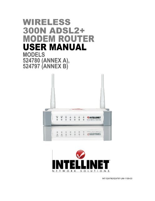
WIRELESS<br />
300N ADSL2+<br />
<strong>MODEM</strong> <strong>ROUTER</strong><br />
<strong>USER</strong> <strong>MANUAL</strong><br />
MODELS<br />
524780 (ANNEX A),<br />
524797 (ANNEX B)<br />
INT-524780/524797-UM-1109-03
Federal Communications Commission<br />
Interference Statement<br />
FCC Part 68<br />
This equipment complies with Part 68 of the FCC Rules. On the bottom of this<br />
device is a label that contains the FCC registration number and ringer<br />
equivalence number (REN) for this equipment. You must provide this information<br />
to the telephone company upon request. The REN is useful to determine the<br />
quantity of devices you may connect to the telephone line and still have all of<br />
those devices ring when your number is called.<br />
In most, but not all areas, the sum of the REN of all devices connected to one<br />
line should not exceed five (5.0). To be certain of the number of devices you may<br />
connect to your line, as determined by the REN, you should contact your local<br />
telephone company to determine the maximum REN for your calling area.<br />
If the modem causes harm to the telephone network, the telephone company<br />
may discontinue your service temporarily. If possible, they will notify you in<br />
advance. But if advance notice isn’t practical, you will be notified as soon as<br />
possible. You will be advised of your right to file a complaint with the FCC.<br />
The telephone company may make changes in its facilities, equipment,<br />
operations or procedures that could affect the proper operation of your<br />
equipment. If they do, you will be notified in advance to give you an opportunity<br />
to maintain uninterrupted telephone service.<br />
If you experience trouble with this modem, contact your dealer for repair/warranty<br />
information. The telephone company may ask you to disconnect this equipment<br />
from the network until the problem has been corrected or you are sure that the<br />
equipment is not malfunctioning.<br />
This equipment may not be used on coin service provided by the telephone<br />
company. Connection to party lines is subject to state tariffs.<br />
Installation<br />
This device is equipped with a USOC RJ11C connector.
FCC Part 15<br />
This equipment has been tested and found to comply with the limits for a Class B<br />
digital device, pursuant to Part 15 of FCC Rules. These limits are designed to<br />
provide reasonable protection against harmful interference in a residential<br />
installation. This equipment generates, uses, and can radiate radio frequency<br />
energy and, if not installed and used in accordance with the instructions, may<br />
cause harmful interference to radio communications. However, there is no<br />
guarantee that interference will not occur in a particular installation. If this<br />
equipment does cause harmful interference to radio or television reception, which<br />
can be determined by turning the equipment off and on, the user is encouraged<br />
to try to correct the interference by one or more of the following measures:<br />
1. Reorient or relocate the receiving antenna.<br />
2. Increase the separation between the equipment and receiver.<br />
3. Connect the equipment into an outlet on a circuit different from that to which<br />
the receiver is connected.<br />
4. Consult the dealer or an experienced radio technician for help.<br />
FCC Caution<br />
This equipment must be installed and operated in accordance with provided<br />
instructions, and a minimum of 20 cm spacing must be provided between<br />
computer-mounted antenna and a person’s body (excluding extremities of hands,<br />
wrists and feet) during wireless modes of operation.<br />
This device complies with Part 15 of the FCC Rules. Operation is subject to the<br />
following two conditions: 1) This device may not cause harmful interference; and<br />
2) This device must accept any interference received, including interference that<br />
may cause undesired operation.<br />
Any changes or modifications not expressly approved by the party responsible<br />
for compliance could void the authority to operate equipment.<br />
FCC Radiation Exposure Statement<br />
This equipment complies with FCC radiation exposure limits set forth for an<br />
uncontrolled environment. In order to avoid the possibility of exceeding these<br />
limits, human proximity to the antenna shall not be less than 20 cm (8 inches)
during normal operation. The antenna(s) used for this transmitter must not be co-<br />
located or operating in conjunction with any other antenna or transmitter.<br />
R&TTE Compliance Statement<br />
This equipment complies with all the requirements of Directive 1999/5/EC of the<br />
European Parliament and the Council of March 9, 1999, on radio equipment and<br />
telecommunication terminal Equipment and the mutual recognition of their<br />
conformity (R&TTE). The R&TTE Directive repeals and replaces in the directive<br />
98/13/EEC (Telecommunications Terminal Equipment and Satellite Earth Station<br />
Equipment) as of April 8, 2000.<br />
Safety<br />
This equipment is designed with the utmost care for the safety of those who<br />
install and use it. However, special attention must be paid to the dangers of<br />
electric shock and static electricity when working with electrical equipment. All<br />
guidelines must therefore be followed at all times to ensure the safe use of the<br />
equipment.<br />
EU Countries Intended for Use<br />
The ETSI version of this device is intended for home and office use in Austria,<br />
Belgium, Denmark, Finland, France, Germany, Greece, Ireland, Italy,<br />
Luxembourg, the Netherlands, Portugal, Spain, Sweden and the United<br />
Kingdom. The ETSI version of this device is also authorized for use in EFTA<br />
member states: Iceland, Liechtenstein, Norway and Switzerland.<br />
EU Countries Not Intended for Use<br />
None.
Contents<br />
1 INTRODUCTION..................................................................... 1<br />
2 HARDWARE .......................................................................... 3<br />
3 SETUP WIZARD ..................................................................... 6<br />
3.1 Getting Started ........................................................................................... 6<br />
3.2 Automatically Set the ISP........................................................................... 9<br />
3.3 Manually Set the ISP................................................................................ 12<br />
4 IP ADDRESS SETTING ..........................................................17<br />
Windows Vista.......................................................................................... 17<br />
Windows XP............................................................................................. 18<br />
Windows 2000.......................................................................................... 19<br />
5 WEB MANAGEMENT CONFIGURATION..................................21<br />
5.1 Quick Setup.............................................................................................. 23<br />
5.2 General Setup .......................................................................................... 25<br />
5.2.1 System............................................................................................... 25<br />
5.2.1.1 Time Zone ................................................................................... 25<br />
5.2.1.2 Password Settings ...................................................................... 26<br />
5.2.1.3 Remote Management.................................................................. 27<br />
5.2.1.4 SNMP.......................................................................................... 29<br />
5.2.2 WAN................................................................................................... 30<br />
5.2.2.1 Channel Config ........................................................................... 30<br />
5.2.2.2 ATM Setting ................................................................................ 34<br />
5.2.2.3 ADSL Setting............................................................................... 36<br />
5.2.2.4 DNS............................................................................................. 37<br />
5.2.2.5 DDNS .......................................................................................... 38<br />
5.2.2.6 RIP .............................................................................................. 39<br />
5.2.3 LAN.................................................................................................... 41<br />
5.2.3.1 DHCP Mode ................................................................................ 43<br />
5.2.3.2 DHCP Relay................................................................................ 43<br />
5.2.3.3 DHCP Server .............................................................................. 44<br />
5.2.3.4 ARP Table................................................................................... 46<br />
5.2.3.5 Bridging ....................................................................................... 46<br />
5.2.4 Wireless ............................................................................................. 47<br />
5.2.4.1 Basic Settings ............................................................................. 47
5.2.4.2 Advanced Settings ...................................................................... 49<br />
5.2.4.3 Security ....................................................................................... 53<br />
5.2.4.4 Access Control ............................................................................ 55<br />
5.2.4.5 WPS ............................................................................................ 56<br />
5.2.5 QoS.................................................................................................... 58<br />
5.2.6 NAT (Network Address Translations) ................................................ 60<br />
5.2.6.1 Port Forwarding............................................................................ 61<br />
5.2.6.2 Port Mapping............................................................................... 62<br />
5.2.6.3 UPNP .......................................................................................... 64<br />
5.2.6.4 IGMP Proxy................................................................................. 65<br />
5.2.7 Firewall............................................................................................... 66<br />
5.2.7.1 IP/Port Filtering ........................................................................... 66<br />
5.2.7.2 MAC Filtering .............................................................................. 68<br />
5.2.7.3 URL Blocking .............................................................................. 70<br />
5.2.7.4 Domain Blocking ......................................................................... 71<br />
5.2.7.5 Routing Configuration ................................................................. 72<br />
5.2.7.6 ACL Configuration....................................................................... 74<br />
5.2.7.7 DMZ............................................................................................. 75<br />
5.3 Status ....................................................................................................... 76<br />
5.3.1 Interface............................................................................................. 77<br />
5.3.2 ADSL ................................................................................................. 78<br />
5.4 Tools......................................................................................................... 79<br />
5.4.1 Configuration Tools............................................................................ 79<br />
5.4.2 Firmware Upgrade ............................................................................. 80<br />
5.4.3 Ping.................................................................................................... 80<br />
5.4.4 ATM Loopback................................................................................... 81<br />
5.4.5 Diagnostic Test .................................................................................. 82<br />
5.4.6 Reboot ............................................................................................... 82<br />
6 TROUBLESHOOTING ............................................................83<br />
7 GLOSSARY ..........................................................................87<br />
8 SPECIFICATIONS .................................................................92
1 Introduction<br />
Thank you for purchasing this INTELLINET NETWORK SOLUTIONS TM<br />
Wireless<br />
300N ADSL2+ Modem Router, Model 524780 (Annex A) or Model 524797<br />
(Annex B).<br />
This is an all-in-one modem, router, Wireless N access point, firewall and Fast<br />
Ethernet four-port switch that allows you to access the Internet and download<br />
music, play interactive games online or surf the Web at double the speed<br />
(depending on operating environment and distance between networked devices)<br />
previously available through ADSL2.<br />
Features of this router include:<br />
• 2T2R MIMO technology for enhanced throughput and coverage<br />
• Supports ADSL standards G.992.1 (G.dmt), G.992.2 (G.lite), G.992.3 (ADSL2),<br />
G.992.4 (splitterless ADSL2) and G.992.5 (ADSL2+) for Annex A<br />
• Supports 24 Mbps ADSL2+ downstream data rate<br />
• Supports Wi-Fi Protected Setup (WPS)<br />
• Supports WEP and WPA/WPA2 (TKIP and AES) data encryption<br />
• Integrated 10/100 Mbps LAN switch with Auto MDI/MDI-X support<br />
• DHCP server assigns IP addresses for all LAN users<br />
• DHCP server supports static lease management<br />
• Supports virtual server, port forwarding and DMZ<br />
• Supports DDNS (dynamic DNS)<br />
• Supports UPnP (Universal Plug and Play)<br />
• Integrated SPI firewall<br />
• QoS (Quality of Service) bandwidth management<br />
• VPN Passthrough (PPTP, IPSec, L2TP)<br />
• Supports SNMP management<br />
• Easy installation through Web-based user interface<br />
• Complies with 2.4 GHz Draft IEEE 802.11n standard and is backward<br />
compatible with IEEE 802.11g/b standards<br />
• System status<br />
• Security log<br />
• Firmware upgradeable<br />
• Three-Year <strong>Warranty</strong><br />
1
Minimum Requirements<br />
• A PC with pre-installed Ethernet adapter (required) and a Web browser<br />
(Internet Explorer 4.0 or higher)<br />
• RJ45 Ethernet crossover cable (included in the package)<br />
• RJ11 (ADSL-ready) phone line<br />
Package Contents<br />
• ADSL 2+ Router (Annex A or B)<br />
• Power adapter<br />
• Ethernet Cat5 RJ45 cable, 1.0 m (3 ft.)<br />
• RJ11 telephone cable, 1.8 m (5.9 ft.)<br />
• Quick installation guide<br />
• Setup CD with user manual<br />
2
2 Hardware<br />
Rear Panel<br />
Item Name Description<br />
Antenna A/B These antennas are 3dBi dipole antennas.<br />
Radio<br />
ON/OFF<br />
Antenna A<br />
Position the switch to activate or deactivate the wireless<br />
functions.<br />
Reset / WPS Reset the router to factory default settings (clear all settings)<br />
or start the WPS function. Press this button and hold for 10<br />
seconds to restore all settings to factory defaults; press this<br />
button for less than 5 seconds to start the WPS function.<br />
1 - 4 The router’s 4 LAN ports are where you connect your LAN’s<br />
PCs, printer servers, hubs and switches, etc.<br />
ADSL Connect the supplied RJ11 telephone line to this port and<br />
your ADSL/telephone network.<br />
Power Plug the included power adapter into the power jack.<br />
3<br />
Antenna B
Front Panel<br />
On the router’s front panel, there are LEDs that inform you of the router’s current<br />
status, as explained below.<br />
LED Status Description<br />
POWER (Green)<br />
WLAN (Yellow)<br />
ADSL (Green)<br />
LAN LNK/ACT (Port 1-4)<br />
On Router is switched on and correctly<br />
On<br />
Off<br />
4<br />
powered.<br />
Wireless LAN WPS is on.<br />
Wireless LAN is disabled.<br />
Blinking Wireless traffic is transmitting or<br />
receiving.<br />
On Connected to an ADSL DSLAN<br />
successfully.<br />
Blinking ADSL line is not connected to Internet.<br />
On<br />
Off<br />
Blinking<br />
The LAN cable is connected to the router.<br />
No network connection.<br />
Network traffic transferring or receiving<br />
through the LAN port.
Installation<br />
1. Connect the router to your ADSL cable through the supplied RJ11 cable.<br />
2. Connect the router to your PC, hub or switch by attaching the Ethernet cable<br />
to the LAN port of the router.<br />
3. Connect the power adapter to the power jack on the rear panel of the router.<br />
4. The ADSL LED will be on if the router is connected to the ADSL cable and<br />
receives the ADSL signals successfully. If the LED is blinking, contact your<br />
ISP (Internet service provider) to check the problem.<br />
NOTE: Use only the power adapter included with the router, and not any other<br />
power adapter.<br />
5
3 Setup Wizard<br />
This router provides a Setup Wizard tool to configure the ADSL settings. This<br />
wizard collects some ISPs’ ADSL settings so that you can easily configure the<br />
router’s ADSL settings by only selecting the ISP vendor from the wizard.<br />
If you cannot find your ISP from the list in the wizard, manually set the ISP<br />
information through the wizard.<br />
3.1 Getting Started<br />
Before starting, check the following items:<br />
1. Make sure that you have connected the ADSL cable to the router correctly.<br />
When the ADSL cable is worked normally, the ADSL LED will be on.<br />
2. Un-install any dial-up programs installed previously for the USB modem or<br />
other dial-up devices.<br />
3. It is recommended that you initially configure the router through the Ethernet<br />
cable before you set the wireless functions.<br />
This wizard can be run in Windows 98SE/Me/2000/XP/Vista. The following<br />
procedures are operated in Windows XP. (Procedures are similar for Windows<br />
98SE/Me/2000/Vista.)<br />
1. Insert the enclosed setup CD into your CD-ROM drive. The Autorun.exe<br />
program should be executed automatically. If not, run Autorun.exe manually<br />
from the “Autorun” folder on the CD.<br />
2. The following screen will be displayed. Click “Setup Wizard.”<br />
6
3. The wizard will run and try to search for the router. If the router is<br />
found, the wizard will guide you to Step 5.<br />
7
4. If the router cannot be found, enter the IP address and the password of the<br />
router to search again. Click “Next” to continue.<br />
5. The wizard will automatically select the country you are in by checking the<br />
language of the operating system in your computer and then advance to the<br />
Select ISP screen. Select the ISP. If you cannot find the ISP, click “Other” to<br />
reselect the country or manually configure the ISP information.<br />
8
3.2 Automatically Set the ISP<br />
If you can find the ISP from the wizard, follow the procedures below to let the<br />
wizard set the ISP settings automatically.<br />
1. Select the ISP of your ADSL service.<br />
2. Enter the username and password that your ISP has provided to you, if<br />
needed. Click “Next.”<br />
9
3. Click “Save” to save the settings and reboot the router.<br />
4. After saving and rebooting the router, the ISP settings are completed. The<br />
wizard will then help to set your computer to obtain an IP address from the<br />
router automatically.<br />
NOTE 1: To use the router to access the Internet, the IP address of each PC<br />
needs to be set in the same network segment as the router. The wizard will help<br />
to set the proper IP address for your computer.<br />
NOTE 2: By default, the router’s DHCP server is enabled. If it is disabled before<br />
running the wizard, the wizard will enable the DHCP server automatically.<br />
10
5. The wizard will try to connect to the ISP you have selected. If the connection<br />
fails, run the wizard to select the ISP again.<br />
6. If you successfully connect to the ISP, you will see the screen below. To<br />
configure additional settings, click “Advanced Settings” to go the Web<br />
management of the router, or click “Finish” to close the wizard.<br />
11
5.3 Manually Set the ISP<br />
If you cannot find the ISP from the wizard, follow the steps below to set the ISP<br />
settings manually.<br />
Before configuring the ISP manually, check with your ISP (Internet service<br />
provider) as to what kind of service is provided, such as PPPoE, PPPoA or<br />
RFC1483/2684. Gather the information as illustrated in the following table and<br />
keep it for reference.<br />
PPPoE VPI/VCI, VC-based/LLC-based multiplexing, Username,<br />
Password (and Service Name).<br />
PPPoA VPI/VCI, VC-based/LLC-based multiplexing, Username,<br />
Password.<br />
RFC1483 Bridged VPI/VCI, VC-based/LLC-based multiplexing to use Bridged<br />
Mode.<br />
RFC1483 Routed VPI/VCI, VC-based/LLC-based multiplexing, IP Address,<br />
1. Select “Other.”<br />
Subnet Mask, Gateway Address, and Domain Name<br />
System (DNS) IP Address (It is a fixed IP Address).<br />
12
2. Check with your ISP as to the connection type of the ADSL line. Select the<br />
Connection Type and click “Next.”<br />
3. Input the VPI, VCI and encapsulation data supplied by your ISP. If the<br />
Connection Type is “Static IP Address,” you need to input the IP address<br />
information supplied by your ISP. For details about each setting, refer to<br />
Section 5.2.<br />
13
4. Enter the username and password that your ISP has provided to you, if<br />
needed. Click “Next.”<br />
5. Click “Save” to save the settings and reboot the router.<br />
6. After saving and rebooting the router, the ISP settings are completed. The<br />
wizard will then help to set your computer to obtain an IP address from the<br />
14
outer automatically.<br />
NOTE 1: To use the router to access the Internet, the IP address of each PC<br />
needs to be set in the same network segment as the router. The wizard will help<br />
to set the proper IP address for your computer.<br />
NOTE 2: By default, the router’s DHCP server is enabled. If it is disabled before<br />
running the wizard, the wizard will enable the DHCP server automatically.<br />
7. The wizard will try to connect to the ISP you have selected. If the connection<br />
fails, run the wizard to select the ISP again.<br />
15
8. If you successfully connect to the ISP, you will see the screen below. To<br />
configure additional settings, click “Advanced Settings” to go to the Web<br />
management of the router, or click “Finish” to close the wizard.<br />
16
4 IP Address Setting<br />
To use the router to access the Internet, the PCs in the network must have am<br />
Ethernet adapter installed and be connected to the router either directly or<br />
through a hub or switch. The TCP/IP protocol of each PC needs to be installed,<br />
and the IP address of each PC has to be set in the same subnet as the router.<br />
The router’s default IP address is 192.168.2.1 and the subnet mask is<br />
255.255.255.0. PCs can be configured to obtain an IP address automatically<br />
through the DHCP server of the router, or with a fixed IP address in order to be in<br />
the same subnet as the router. By default, the DHCP server of the router is<br />
enabled and will dispatch an IP address to the PC in the range of 192.168.2.100<br />
to 192.168.2.200. It is strongly recommended that you obtain the IP address<br />
automatically.<br />
This section shows you how to configure your PC so that it can obtain an IP<br />
address automatically for Windows 95/98/Me, 2000 or NT operating systems. For<br />
other operating systems (Macintosh, Sun, etc.), follow the manual of the<br />
operating systems. The following are step-by-step procedures for configuring<br />
your PC to obtain an IP address automatically for Windows Vista, Windows XP<br />
and Windows 2000.<br />
Windows Vista<br />
1. Click “Start” and select “Settings,” then select “Control Panel.” Double-click<br />
“Network and Sharing Center”; the Network and Sharing Center window will<br />
appear.<br />
2. Click “Manage network connections”; right-click on the Local Area Connection<br />
icon and select “Properties.” The Local Area Connection window will appear.<br />
3. Check your list of Network Components. You should see “Internet Protocol<br />
Version 4 (TCP/IPv4)” on your list. Select it and click “Properties.”<br />
4. In the Internet Protocol Version 4 (TCP/IPv4) Properties window, select<br />
“Obtain an IP address automatically” and “Obtain DNS server address<br />
automatically,” as shown on the following screen.<br />
17
5. Click “OK” to confirm the setting. Your PC will now obtain an IP address<br />
automatically from your router’s DHCP server.<br />
NOTE: Make sure that the router’s DHCP server is the only DHCP server<br />
available on your LAN.<br />
Windows XP<br />
1. Click “Start” and select “Control Panel”; then double-click “Network<br />
Connections.” The Network Connections window will appear.<br />
2. Right-click on the Local Area Connection icon and select “Properties.” The<br />
Local Area Connection window will appear.<br />
3. Check your list of Network Components. You should see “Internet Protocol<br />
[TCP/IP]” on your list. Select it and click “Properties.”<br />
4. In the Internet Protocol (TCP/IP) Properties window, select “Obtain an IP<br />
address automatically” and “Obtain DNS server address automatically,” as<br />
shown on the following screen.<br />
18
5. Click “OK” to confirm the setting. Your PC will now obtain an IP address<br />
automatically from your router’s DHCP server.<br />
NOTE: Make sure that the router’s DHCP server is the only DHCP server<br />
available on your LAN.<br />
Windows 2000<br />
1. Click “Start” and select “Settings,” then click “Control Panel.” The Control<br />
Panel window will appear.<br />
2. Double-click the Network and Dial-up Connections icon. In the Network and<br />
Dial-up Connection window, double-click the Local Area Connection icon. The<br />
Local Area Connection window will appear.<br />
3. In the Local Area Connection window, click “Properties.”<br />
4. Check your list of Network Components. You should see “Internet Protocol<br />
[TCP/IP]” on your list. Select it and click “Properties.”<br />
19
5. In the Internet Protocol (TCP/IP) Properties window, select “Obtain an IP<br />
address automatically” and “Obtain DNS server address automatically,” as<br />
shown on the following screen.<br />
6. Click “OK” to confirm the setting. Your PC will now obtain an IP address<br />
automatically from your router’s DHCP server.<br />
NOTE: Make sure that the router’s DHCP server is the only DHCP server<br />
available on your LAN.<br />
20
5 Web Management Configuration<br />
Once you have configured your PCs to obtain an IP address automatically, the<br />
router’s DHCP server will automatically give your LAN clients an IP address. By<br />
default, the router’s DHCP server is enabled so you can obtain an IP address<br />
automatically.<br />
Once your PC has obtained an IP address from your router, enter the default IP<br />
address 192.168.2.1 (router’s IP address) into your PC’s Web browser and press<br />
on your keyboard.<br />
The login screen below will appear. Fill in the “User Name” and “Password” text<br />
fields, then click “OK” to log in. By default, the username is “admin” and the<br />
password is “1234.” For security reasons, it is recommended that you change the<br />
password as soon as possible.<br />
The HOME screen screen below will appear. The Home Screen is divided into<br />
four sections: Quick Setup, General Setup, Status, Tools.<br />
21
Quick Setup (Section 5.1)<br />
The Quick Setup Wizard provides only the necessary configurations to connect<br />
your router to your Internet service provider (ISP).<br />
General Setup (Section 5.2)<br />
The router supports advanced functions like virtual server, access control, hacker<br />
attack detection and DMZ. It’s highly recommended that you keep the default<br />
settings.<br />
Status (Section 5.3)<br />
The status section provides the following information about your router:<br />
hardware/firmware version, serial number and its current operating status.<br />
Tools (Section 5.4)<br />
Tools include configuration tools, firmware upgrading and reset configuration<br />
tools that allow you to back up, restore or restore to factory default settings.<br />
22
5.1 Quick Setup<br />
The Quick Setup section is designed to get you using the router as quickly as<br />
possible. Before configuring the router, check with your ISP (Internet service<br />
provider) as to what kind of the service is provided, such as PPPoE, PPPoA or<br />
RFC1483/2684. Gather the information as illustrated in the table below and keep<br />
it for reference.<br />
PPPoE VPI/VCI, VC-based/LLC-based multiplexing, Username,<br />
Password (and Service Name).<br />
PPPoA VPI/VCI, VC-based/LLC-based multiplexing, Username,<br />
Password.<br />
RFC1483 Bridged VPI/VCI, VC-based/LLC-based multiplexing to use Bridged<br />
Mode.<br />
RFC1483 Routed VPI/VCI, VC-based/LLC-based multiplexing, IP Address,<br />
Subnet Mask, Gateway Address, and Domain Name<br />
System (DNS) IP Address (It is a fixed IP Address).<br />
1. Click “Quick Setup” and the following screen will be displayed.<br />
23
2. Select the country you’re in and your ISP (Internet service provider).<br />
3. Enter the username and password your ISP has provided to you, if needed.<br />
Click “Finish” to save the settings.<br />
4. Click “Commit and Reboot” to reboot the router.<br />
24
5.2 General Setup<br />
Start your Web browser and log on to the Web management interface of the<br />
router, then either click “General Setup” on the left menu or click the “General<br />
Setup” link at the upper-right corner of the Web management interface.<br />
5.2.1 System<br />
This screen includes the basic configuration tools for the router’s remote<br />
management access function.<br />
5.2.1.1 Time Zone<br />
Time Zone allows your router to set its time, especially useful when recording<br />
System Log entries.<br />
Parameter Description<br />
Current Time The current time of the specified time zone. You can set<br />
the current time yourself or configure it via SNTP server.<br />
Time Zone Select Select the time zone of the country you are in. The router<br />
Enable SNTP client<br />
update<br />
will set its time based on your selection.<br />
Check the box to enable the router to update time from<br />
the SNTP server.<br />
SNTP server The IP address or the host name of the SNTP server.<br />
You can select from the list or set it manually.<br />
25
When you finish, click “Apply Changes.” You’ll see the following message<br />
displayed on Web browser.<br />
Click “Continue” to save the settings made and go back to the Web management<br />
interface; click “Apply” to save the settings and restart the router so the settings<br />
will take effect after it reboots.<br />
5.2.1.2 Password Settings<br />
This screen allows you to set the password to access the Web server of the<br />
router. Select the “admin” (as administrator) or “user” (as user) account and<br />
configure the password.<br />
When you finish, click “Apply Changes.”<br />
If the passwords you entered in the “New Password” and “Confirmed Password”<br />
fields are not the same, you’ll see the following message:<br />
Re-enter the new password again when you see above message.<br />
26
If you see the following message:<br />
It means the content in the “Current Password” field is wrong. Click “OK” to go<br />
back to the previous menu and input the current password again.<br />
If the current and new passwords are correctly entered, after you click “Apply”<br />
you’ll be prompted to input your new password:<br />
Use the new password to enter the Web management interface again, and you<br />
should be able to log in with the new password.<br />
5.2.1.3 Remote Management<br />
The Remote Access function can secure remote host access to your router from<br />
LAN and WAN interfaces for some services provided by the router. These<br />
services include Telnet, FTP, TFTP, HTTP, SNMP and PING.<br />
Click the “System” menu on the left of the Web management interface, then click<br />
“Remote Management” and the following screen will be displayed on your Web<br />
browser.<br />
27
Parameter Description<br />
LAN Check/un-check the services on the LAN column to allow/<br />
disallow the services access from the LAN side.<br />
WAN Check/un-check the services on the WAN column to allow/<br />
disallow the services access from the WAN side.<br />
WAN Port This field allows the user to specify the port corresponding to<br />
the service. Take the HTTP service, for example: When it is<br />
changed to 8080, the HTTP server address for the WAN side<br />
is http://dsl_addr:8080, where “dsl addr” is the WAN-side IP<br />
address of the router.<br />
When you finish, click “Apply Changes.” You’ll see the following message<br />
displayed on Web browser.<br />
28
Click “Continue” to save the settings made and go back to the Web management<br />
interface; click “Apply” to save the settings made and restart the router so the<br />
settings will take effect after it reboots.<br />
5.2.1.4 SNMP<br />
Simple Network Management Protocol (SNMP) is a troubleshooting and<br />
management protocol that uses the UDP protocol on Port 161 to communicate<br />
between clients and servers. The router can be managed locally or remotely by<br />
SNMP protocol.<br />
Parameter Description<br />
SNMP Select “Disable” or “Enable” to disable or enable the<br />
SNMP feature.<br />
System Description Enter the system description of the router.<br />
System Contact Enter the contact person and/or contact information for<br />
the router.<br />
System Name Assign an administrative name for the router.<br />
System Location The physical location of the router.<br />
System Object ID This is the vendor object identifier: the vendor’s<br />
authoritative identification of the network management<br />
subsystem contained in the entity.<br />
Trap IP Address Destination IP address of the SNMP trap.<br />
Community name<br />
(read-only)<br />
Name of the read-only community. This read-only<br />
community allows read operation to all objects in the<br />
MIB.<br />
29
Community name<br />
(write-only)<br />
Name of the write-only community. This write-only<br />
community allows write operation to the objects defines<br />
as read-writable in the MIB.<br />
When you finish, click “Apply Changes.” You’ll see the following message<br />
displayed on Web browser.<br />
Click “Continue” to save the settings made and go back to the Web management<br />
interface; click “Apply” to save the settings made and restart the router so the<br />
settings will take effect after it reboots.<br />
5.2.2 WAN<br />
Use the WAN Settings screen if you have already configured the Quick Setup<br />
Wizard section and you would like to change your Internet connection type. The<br />
WAN Settings screen allows you to specify the type of WAN port connection you<br />
want to establish with your ISP. The WAN settings offer the following selections<br />
for the router’s WAN port: Channel, ATM Setting, ADSL Setting, DNS, DDNS and<br />
RIP.<br />
5.2.2.1 Channel Config<br />
The router supports eight ATM permanent virtual channels (PVCs) at the most.<br />
This screen is used to configure the parameters for the channel operation modes<br />
of your router. Before configuring the router, check with your ISP as to what kind<br />
of service is provided, such as PPPoE, PPPoA or RFC1483/2684. Gather the<br />
information as illustrated in the table below and keep it for reference.<br />
30
PPPoE VPI/VCI, VC-based/LLC-based multiplexing, Username,<br />
Password (and Service Name).<br />
PPPoA VPI/VCI, VC-based/LLC-based multiplexing, Username,<br />
Password.<br />
RFC1483 Bridged VPI/VCI, VC-based/LLC-based multiplexing to use Bridged<br />
Mode.<br />
RFC1483 Routed VPI/VCI, VC-based/LLC-based multiplexing, IP Address,<br />
Subnet Mask, Gateway Address, and Domain Name<br />
System (DNS) IP Address (It is a fixed IP Address).<br />
RFC1483 MER VPI/VCI, VC-based/LLC-based multiplexing, IP Address,<br />
Subnet Mask, Gateway Address, and Domain Name<br />
System (DNS) IP Address.<br />
31
Parameter Description<br />
VPI VPI is a virtual path that determines the way an ATM cell<br />
should be routed. The VPI is an 8-bit (in UNI) or 12-bit (in<br />
NNI) number that is included in the header of an ATM<br />
cell. The valid range for the VPI is 0 to 255. Enter the VPI<br />
assigned by the ISP.<br />
VCI VCI is the label given to an ATM VC to identify it and<br />
determine its destination. The VCI is a 16-bit number that<br />
is included in the header of an ATM cell. The valid VCI<br />
range is 32 to 65535. Enter the VCI assigned by the ISP.<br />
Encapsulation Check with your ISP for the method of multiplexing.<br />
Channel Mode There are five kinds of channel modes you can select for<br />
an ADSL connection. Check with your ISP for the method<br />
of the ADSL connection.<br />
Enable NAPT Enable or disable NAPT, an Internet standard that<br />
enables a local-area network (LAN) to use one set of IP<br />
addresses for internal traffic and a second set of<br />
addresses for external traffic. When NAPT is enabled,<br />
the router will help to make all necessary IP address<br />
translations for the PC connected to the router to access<br />
the Internet.<br />
Admin Status Enable or disable the PVC channel setting.<br />
User Name Enter the username exactly as your ISP assigned it.<br />
Password Enter the password that your ISP has assigned to you.<br />
Type<br />
Continuous – The connection will be kept always on. If<br />
the connection is interrupted, the router will re-connect<br />
automatically.<br />
Connect on Demand – Only connects when you want to<br />
surf the Internet. “Idle Time” is set to stop the connection<br />
when the network traffic is not sending or receiving after<br />
an idle time.<br />
Manual – After you have selected this option, go to the<br />
Status screen and click “Connect.” The router will<br />
connect to the ISP. If you want to stop the connection,<br />
click “Disconnect.”<br />
32
Idle Time (ms) “Idle Time” is set to stop the connection when the<br />
network traffic is not sending or receiving after an idle<br />
time.<br />
Type Fixed IP – Set the static IP Address to the router. Enter<br />
the IP address your ISP has assigned.<br />
DHCP – To get the IP address from the ISP directly.<br />
Local IP Address Set the IP address obtained from your ISP.<br />
Remote IP Address Enter the remote IP address assigned by your ISP.<br />
Subnet Mask Enter the subnet mask assigned by your ISP.<br />
Unnumbered The IP Unnumbered configuration allows you to enable<br />
IP processing on a serial interface without assigning it an<br />
explicit IP address. When it is enabled, the router’s WAN<br />
IP address can “borrow” the IP address of another<br />
interface already configured on the router, which<br />
conserves network and address space. Check it if you<br />
want to assign the WAN IP address from other interface,<br />
such as a client’s IP address.<br />
Default Route When “Default Router” is enabled, all the packets for<br />
destinations not known by the router’s routing table are<br />
sent to the default route. By default, it is enabled.<br />
Add/Modify These buttons are for you to maintain the channel<br />
configuration settings.<br />
Current ATM VC Table The channel you have configured will be listed here. You<br />
can select the VC channel to Edit or Delete.<br />
Delete Selected If you want to delete a specific VC channel entry, check<br />
Enable Auto-PVC<br />
Search<br />
the “select” box of the VC channel you want to delete,<br />
then click “Delete Selected.”<br />
Check the box and click “Apply” to enable the auto PVC<br />
search function.<br />
VPI VPI is a virtual path that determines the way an ATM cell<br />
should be routed.<br />
VCI VCI is the label given to an ATM VC to identify it and<br />
determine its destination.<br />
Add/Delete These buttons are for you to maintain the Current Auto-<br />
PVC Table.<br />
33
When you finish, click “Apply Changes.” You’ll see the following message<br />
displayed on Web browser.<br />
Click “Continue” to save the settings made and go back to the Web management<br />
interface; click “Apply” to save the settings made and restart the router so the<br />
settings will take effect after it reboots.<br />
5.2.2.2 ATM Setting<br />
The screen is for ATM PVC QoS parameters setting.<br />
Parameter Description<br />
VPI<br />
VPI is a virtual path that determines the way an ATM cell<br />
should be routed. The VPI is an 8-bit (in UNI) or 12-bit (in<br />
NNI) number that is included in the header of an ATM<br />
cell. The valid range for the VPI is 0 to 255. Enter the VPI<br />
assigned by the ISP.<br />
VCI VCI is the label given to an ATM VC to identify it and<br />
determine its destination. The VCI is a 16-bit number that<br />
34
is included in the header of an ATM cell. The valid VCI<br />
range is 32 to 65535. Enter the VCI assigned by the ISP.<br />
QoS UBR (Unspecified Bit Rate) – Select UBR for applications<br />
that are non-time sensitive, such as e-mail.<br />
CBR (Constant Bit Rate) – This class is used for<br />
emulating circuit switching. The cell rate is constant with<br />
time. Select CBR to specify fixed (always on) bandwidth<br />
for voice or data traffic.<br />
nrtVBR (non-real time Variable Bit Rate) – This class<br />
allows users to send traffic at a rate that varies with time<br />
depending on the availability of user information.<br />
Statistical multiplexing is provided to make optimum use<br />
of network resources. Multimedia e-mail is an example of<br />
nrtVBR.<br />
rtVBR (real time Variable Bit Rate) – This class is similar<br />
to nrtVBR but is designed for applications that are<br />
sensitive to cell-delay variation. Examples for real-time<br />
VBR are voice with speech activity detection (SAD) and<br />
interactive compressed video.<br />
PCR Divide the DSL line rate (bps) by 424 (the size of an ATM<br />
cell) to find the PCR (Peak Cell Rate). This is the<br />
maximum rate at which the sender can send cells.<br />
CDVT PCR generally is coupled with the CDVT (Cell Delay<br />
Variation Tolerance), which indicates how much jitter is<br />
allowable.<br />
SCR SCR (Sustain Cell Rate) is the average rate over a long<br />
interval, in the order of the connection lifetime.<br />
MBS MBS (Maximum Burst Size) refers to the maximum<br />
number of cells that can be sent at the peak rate. Enter<br />
the MBS, which is less than 65535.<br />
Current ATM VC Table The channel you have configured with regard to the ATM<br />
settings will be listed here.<br />
When you finish, click “Apply Changes.” You’ll see the following message<br />
displayed on Web browser.<br />
35
Click “Continue” to save the settings made and go back to the Web management<br />
interface; click “Apply” to save the settings made and restart the router so the<br />
settings will take effect after it reboots.<br />
5.2.2.3 ADSL Setting<br />
The screen allows you to select any combination of DSL modes.<br />
Parameter Description<br />
ADSL modulation Choose preferred ADSL standard protocols.<br />
AnnexL Option Enable/Disable ADSL2/ADSL2+ Annex L capability.<br />
AnnexM Option Enable/Disable ADSL2/ADSL2+ Annex M capability.<br />
ADSL Capability Bitswap Enable – Enable/Disable bitswap capability.<br />
SRA Enable – Enable/Disable SRA (seamless rate<br />
adaptation) capability.<br />
ADSL Tone Choose tones to be masked. The masked tones will not<br />
36
carry any data. Click “Tone Mask” to mask the tone<br />
number you have selected or all the tone numbers.<br />
When you finish, click “Apply Changes.” You’ll see the following message<br />
displayed on Web browser.<br />
Click “Continue” to save the settings made and go back to the Web management<br />
interface; click “Apply” to save the settings made and restart the router so the<br />
settings will take effect after it reboots.<br />
5.2.2.4 DNS<br />
A Domain Name System (DNS) server is like an index of IP addresses and Web<br />
addresses. If you type a Web address into your browser, such as<br />
“www.router.com,” a DNS server will find that name in its index and the matching<br />
IP address. This screen is used to select the way to obtain the IP addresses of<br />
the DNS servers.<br />
37
Parameter Description<br />
Attain DNS<br />
Automatically<br />
Select this item if you want to use the DNS servers<br />
obtained from ISP.<br />
Set DNS Manually Select this item to specify up to three DNS IP addresses.<br />
When you finish, click “Apply Changes.” You’ll see the following message<br />
displayed on Web browser.<br />
Click “Continue” to save the settings made and go back to the Web management<br />
interface; click “Apply” to save the settings made and restart the router so the<br />
settings will take effect after it reboots.<br />
5.2.2.5 DDNS<br />
Dynamic DNS (DDNS) allows you to map the static domain name to a dynamic<br />
IP address. You must get an account, password and your static domain name<br />
from the DDNS service providers.<br />
38
Parameter Description<br />
Enable Check the box to enable DDNS function.<br />
DDNS Provider Select your DDNS service provider here. This router<br />
supports DynDNS and TZO service providers.<br />
Host Name Enter the domain name you’ve obtained from the DDNS<br />
service provider.<br />
Username Enter the username assigned by the DDNS service<br />
provider.<br />
Password Enter the password assigned by the DDNS service<br />
provider.<br />
E-mail Enter the e-mail account that your DDNS service<br />
provider assigned to you.<br />
Key Enter the password that your DDNS service provider<br />
assigned to you.<br />
Add/Modify/Remove These buttons are for you to maintain the DDNS table.<br />
Dynamic DDNS Table The DDNS you have configured will be added to the list.<br />
When you finish, click “Apply Changes.” You’ll see the following message<br />
displayed on Web browser.<br />
Click “Continue” to save the settings made and go back to the Web management<br />
interface; click “Apply” to save the settings made and restart the router so the<br />
settings will take effect after it reboots.<br />
5.2.2.6 RIP<br />
RIP is an Internet protocol you can set up to share routing-table information with<br />
other routing devices on your LAN, at your ISP’s location, or on remote networks<br />
connected to your network via the ADSL line.<br />
Most small home or office networks do not need to use RIP; they have only one<br />
router, such as this one, and one path to an ISP. In these cases, there is no need<br />
39
to share routes because all Internet data from the network is sent to the same<br />
ISP gateway.<br />
You may want to configure RIP if any of the following circumstances apply to<br />
your network:<br />
• Your home network setup includes an additional router or RIP-enabled PC<br />
(other than this one). This router and the other router will need to communicate<br />
via RIP to share their routing tables.<br />
• Your network connects via the ADSL line to a remote network, such as a<br />
corporate network. In order for your LAN to learn the routes used within your<br />
corporate network, they should both be configured with RIP.<br />
• Your ISP requests that you run RIP for communication with devices on their<br />
network.<br />
Parameter Description<br />
RIP Enable/disable the RIP feature.<br />
Interface Select the interface that you want to enable the RIP<br />
Receive Mode<br />
feature.<br />
Indicate the RIP version in which information must be<br />
passed to the DSL device in order for it to be accepted<br />
into its routing table.<br />
Send Mode Indicate the RIP version this interface will use when it<br />
sends its route information to other devices.<br />
40
RIP Config Table The RIP you have configured will be listed in the table. If<br />
you want to delete some settings, select the settings and<br />
click “Delete Selected.”<br />
When you finish, click “Apply Changes.” You’ll see the following message<br />
displayed on Web browser.<br />
Click “Continue” to save the settings made and go back to the Web management<br />
interface; click “Apply” to save the settings made and restart the router so the<br />
settings will take effect after it reboots.<br />
5.2.3 LAN<br />
This screen is used to configure the LAN interface of this router. You can set IP<br />
address, subnet mask and IGMP Snooping.<br />
41
Parameter Description<br />
Interface Name The interface name is “br0.”<br />
IP Address<br />
Enter the IP address of the ADSL router for the local user to<br />
access the router’s Web screen. By default, the IP address is<br />
192.168.2.1.<br />
Subnet Mask Enter the subnet mask of the ADSL router. By default, the<br />
subnet mask is 255.255.255.0.<br />
Secondary IP Assign a second IP address to the LAN.<br />
IGMP Snooping Enable/disable the IGMP snooping function for the multiple<br />
Ethernet to<br />
Wireless<br />
Blocking<br />
bridged LAN ports. When “IGMP Snoop” (Internet Group<br />
Management Protocol Snoop) is enabled, the router can make<br />
intelligent multicast forwarding decisions by examining the<br />
contents of each frame’s IP header. Without the function, the<br />
router will broadcast the multicast packets to each port and<br />
may create excessive traffic on the network and degrade the<br />
performance of the network.<br />
Enable/disable the “Ethernet to Wireless Blocking.” When this<br />
function is enabled, the traffic between Ethernet and wireless<br />
interfaces is not allowed.<br />
When you finish, click “Apply Changes.” You’ll see the following message<br />
displayed on Web browser.<br />
Click “Continue” to save the settings made and go back to the Web management<br />
interface; click “Apply” to save the settings made and restart the router so the<br />
settings will take effect after it reboots.<br />
42
5.2.3.1 DHCP Mode<br />
You can configure your network and the router to use the Dynamic Host<br />
Configuration Protocol (DHCP). This screen allows you to select the DHCP mode<br />
that this router will support.<br />
There are two different DHCP modes: DHCP Server and DHCP Relay. When the<br />
router is acting as a DHCP server, configure it on the DHCP Server screen; while<br />
acting as a DHCP relay, you can set up the relay on the DHCP Relay screen.<br />
5.2.3.2 DHCP Relay<br />
Some ISPs perform the DHCP server function for their customers’ home/small<br />
office network. In this case, you can configure this device to act as a DHCP relay<br />
agent. When a user’s computer on your network requests Internet access, the<br />
router contacts your ISP to obtain the IP configuration, and then forwards that<br />
information to the computer.<br />
43
Parameter Description<br />
DHCP Server Address Specify the IP address of your ISP’s DHCP server.<br />
Requests for IP information from your LAN interface will<br />
be passed to the default gateway, which should route the<br />
request appropriately.<br />
When you finish, click “Apply Changes.” You’ll see the following message<br />
displayed on Web browser.<br />
Click “Continue” to save the settings made and go back to the Web management<br />
interface; click “Apply” to save the settings made and restart the router so the<br />
settings will take effect after it reboots.<br />
5.2.3.3 DHCP Server<br />
When the DHCP server is enabled, the router will automatically give your LAN<br />
clients an IP address. If the DHCP is not enabled, then you’ll need to manually<br />
set your LAN clients’ IP addresses.<br />
44
Parameter Description<br />
LAN IP Address The current IP address of the router.<br />
Subnet Mask The current subnet mask of the router.<br />
IP Pool Range You can select a particular IP address range for your<br />
DHCP server to issue IP addresses to your LAN clients.<br />
By default, the IP range is from 192.168.2.100 to<br />
192.168.2.200.<br />
Show Client Click and a table is displayed, presenting the assigned IP<br />
address, MAC address and time expired for each DHCP<br />
leased client.<br />
Subnet Mask Enter the subnet mask for LAN clients.<br />
Max Lease Time In the Lease Time setting, you can specify the time<br />
period that the DHCP server lends an IP address to your<br />
LAN clients. The DHCP will change your LAN clients’ IP<br />
address when this time threshold period is terminated.<br />
Domain Name A user-friendly name that refers to the group of hosts<br />
(subnet) that will be assigned addresses from this pool.<br />
Gateway Address The IP address of the router.<br />
MAC Base Assignment Click and you can assign a static IP address to the<br />
computer with the designated MAC address. The MAC<br />
address is the 12-digit hexadecimal number; for example,<br />
“00-d0-59-c6-12-43.” The assigned IP address should be<br />
a unique IP address.<br />
When you finish, click “Apply Changes.” You’ll see the following message<br />
displayed on Web browser.<br />
Click “Continue” to save the settings made and go back to the Web management<br />
interface; click “Apply” to save the settings made and restart the router so the<br />
settings will take effect after it reboots.<br />
45
5.2.3.4 ARP Table<br />
ARP is the Address Resolution Protocol. Its job is to match MAC addresses to IP<br />
addresses and vice versa (matching IP addresses to MAC addresses). This<br />
screen lists the IP addresses and the matched MAC addresses in the network.<br />
5.2.3.5 Bridging<br />
You can enable/disable the Spanning Tree Protocol and set the MAC address<br />
aging time on this screen.<br />
Parameter Description<br />
Aging Time Set the Ethernet address ageing time. After the aging<br />
time of not having seen a frame coming from a certain<br />
address, the bridge will time out (delete) and not forward<br />
the frame.<br />
802.1d Spanning Tree Enable/disable the Spanning Tree Protocol. When this<br />
feature is enabled, this router will use the Spanning Tree<br />
Protocol to prevent a network loop from forming in the<br />
network (LAN side).<br />
46
When you finish, click “Apply Changes.” You’ll see the following message<br />
displayed on Web browser.<br />
Click “Continue” to save the settings made and go back to the Web management<br />
interface; click “Apply” to save the settings made and restart the router so the<br />
settings will take effect after it reboots.<br />
5.2.4 Wireless<br />
The router builds a wireless LAN and can let all IEEE 802.11b, IEEE 801.11g or<br />
IEEE 802.1n wireless stations connect to your intranet. It supports WEP, WPA<br />
and WPA2 encryption to enhance the security of your wireless network. It also<br />
supports WPS so you can easily set up the wireless connection between the<br />
router and other stations.<br />
5.2.4.1 Basic Settings<br />
This section provides the wireless network settings for your router. You can<br />
enable the wireless AP function here.<br />
47
Parameter Description<br />
Disable Wireless LAN<br />
Interface<br />
Check to deactivate the wireless function of the router.<br />
When this is activated, the router will not be an access<br />
point for other wireless clients to connect wirelessly.<br />
Band Select the radio band from one of the following options:<br />
• 2.4GHz(B): only allows 802.11b wireless network<br />
clients to connect to this router (maximum transfer rate<br />
is 11 Mbps).<br />
• 2.4 GHz (G): only allows 802.11g wireless network<br />
clients to connect to this router (maximum transfer rate<br />
is 54 Mbps).<br />
• 2.4 GHz (B+G): only allows 802.11b and 802.11g<br />
wireless network clients to connect to this router<br />
(maximum transfer rate is 11 Mbps for 802.11b clients;<br />
54 Mbps for 802.11g clients).<br />
• 2.4 GHz (N): only allows 802.11n wireless network<br />
clients to connect to this router (maximum transfer rate<br />
is 150 Mbps).<br />
• 2.4 GHz (G+N): only allows 802.11g and 802.11n<br />
wireless network clients to connect to this router<br />
(maximum transfer rate is 54 Mbps for 802.11g clients;<br />
150 Mbps for 802.11n clients).<br />
• 2.4 GHz (B+G+N): allows 802.11b, 802.11g and<br />
802.11n wireless network clients to connect to this<br />
router (maximum transfer rate is 11 Mbps for 802.11b<br />
clients; 54 Mbps for 802.11g clients; 150 Mbps for<br />
802.11n clients).<br />
Mode Set the router to act in AP, Client or WDS mode.<br />
SSID The SSID (up to 32 printable ASCII characters) is the<br />
unique name identified in a WLAN. The ID prevents the<br />
unintentional merging of two co-located WLANs. The<br />
default SSID of the router is “default.”<br />
Channel Width Sets the channel width of the wireless radio. Do not<br />
modify the default value if you don’t know what it is. The<br />
default setting is “Auto 20/40 MHz.”<br />
48
Control Sideband Select the upper band or lower band for your radio<br />
frequency. While “Upper” is selected, the channel options<br />
are from 5 to 11. While “Lower” is selected, the channel<br />
options are from 1 to 7.<br />
Channel Number This is the radio channel used by the wireless LAN. All<br />
devices in the same wireless LAN should use the same<br />
channel. Select the country and designate a channel that<br />
the router will use. To let the router automatically find an<br />
available channel with the highest signal strength, select<br />
“Auto.”<br />
Radio Power (mW) Sets the maximum output power of the router. The higher<br />
the output power, the wider the coverage range.<br />
Associated Clients Click to see the wireless clients connected to the router.<br />
When you finish, click “Apply Changes.” You’ll see the following message<br />
displayed on Web browser.<br />
Click “Continue” to save the settings made and go back to the Web management<br />
interface; click “Apply” to save the settings made and restart the router so the<br />
settings will take effect after it reboots.<br />
5.2.4.2 Advanced Settings<br />
This screen allows advanced users who have sufficient knowledge of wireless<br />
LANs to make configuration changes. These settings shouldn’t be changed<br />
unless you know exactly what will happen as a result.<br />
49
Parameter Description<br />
Authentication Type There are three authentication types: Open System,<br />
Shared Key and Auto.<br />
• Open System authentication is not required to be<br />
successful, as a client may decline to authenticate with<br />
any other particular client.<br />
• Shared Key is only available if the WEP option is<br />
implemented. Shared Key authentication supports<br />
authentication of clients as either a member of those<br />
who know a shared secret key or a member of those<br />
who do not. IEEE 802.11 Shared Key authentication<br />
accomplishes this without the need to transmit the<br />
secret key in clear. Requires the use of the WEP<br />
privacy mechanism.<br />
50
Fragmentation<br />
Threshold<br />
• Auto is the default authentication algorithm. It will<br />
change its authentication type automatically to fulfill a<br />
client’s requirement.<br />
Fragment Threshold specifies the maximum size of a<br />
packet during the fragmentation of data to be transmitted.<br />
If you set this value too low, it will result in bad<br />
performance. Enter a value from 256 to 2346.<br />
RTS Threshold This value should remain at its default setting of 2347.<br />
Should you encounter inconsistent data flow, only minor<br />
modifications are recommended. If a network packet is<br />
smaller than the preset “RTS Threshold” size, the<br />
RTS/CTS mechanism will not be enabled. The wireless<br />
router sends Request to Send (RTS) frames to a<br />
particular receiving station and negotiates the sending of<br />
a data frame. After receiving an RTS, the wireless station<br />
responds with a Clear to Send (CTS) frame to<br />
acknowledge the right to begin transmission.<br />
Beacon Interval This is the interval of time that this wireless router<br />
broadcasts a beacon, which is used to synchronize the<br />
wireless network. The range for the beacon period is 20<br />
to 1024, with a default value of 100 (milliseconds).<br />
Data Rate This setting depends on the speed of your wireless<br />
network. You should select from a range of transmission<br />
speeds, or you can select “Auto” to have the wireless<br />
router automatically use the fastest possible data rate<br />
and enable the Auto-Fallback feature, which negotiates<br />
the best possible connection speed between the router<br />
and a wireless client. The default setting is “Auto.”<br />
Preamble Type This defines the length of the CRC (Cyclic Redundancy<br />
Check) block for communication between the router and<br />
wireless stations. Make sure to select the appropriate<br />
preamble type. Note that high network traffic areas<br />
should use “Short Preamble.” CRC is a common<br />
technique for detecting data transmission errors.<br />
Broadcast SSID If this option is enabled, the router will automatically<br />
51
transmit the network name (SSID) into open air at regular<br />
intervals. This feature is intended to allow clients to<br />
dynamically discover the router. If this option is disabled,<br />
the router will hide its SSID. When this is done, the<br />
clients cannot directly discover the router and MUST be<br />
configured with the SSID for access to the router. It is<br />
used to protect your network from being accessed easily.<br />
Relay Blocking When you enable this function, wireless clients will not be<br />
able to directly access other wireless clients.<br />
Protection This is also called CTS Protection. It is recommended to<br />
enable the protection mechanism. This mechanism can<br />
decrease the rate of data collision between 802.11b and<br />
802.11g/802.11n wireless stations. When the protection<br />
mode is enabled, the throughput of the AP will be a little<br />
lower.<br />
Aggregation This is used to join multiple data packets for transmission<br />
as a single unit to increase network efficiency.<br />
Short GI The 802.11n draft specifies two guard intervals: 400 ns<br />
(short) and 800 ns (long). Support of the 400 ns GI is<br />
optional for transmit and receive. Enabling this function<br />
will increase network efficiency.<br />
When you finish, click “Apply Changes.” You’ll see the following message<br />
displayed on Web browser.<br />
Click “Continue” to save the settings made and go back to the Web management<br />
interface; click “Apply” to save the settings made and restart the router so the<br />
settings will take effect after it reboots.<br />
52
5.2.4.3 Security<br />
This router provides complete wireless LAN security functions, including WEP,<br />
IEEE 802.1x, IEEE 802.1x with WEP, WPA with pre-shared key and WPA with<br />
RADIUS. With these security functions, you can protect your wireless LAN from<br />
illegal access. Make sure your wireless stations use the same security function.<br />
Parameter Description<br />
Encryption Choose “None” to disable the encryption, or select<br />
“WEP,” “WPA(TKIP),” “WPA2(AES)” or “WPA2 Mixed”<br />
mode for security. When “WEP” is enabled, click “Set<br />
WEP Key” to choose the default key and set the four sets<br />
of WEP keys.<br />
• WEP is a lower level of security than WPA, and<br />
supports 64-bit and 128-bit key lengths to encrypt the<br />
wireless data.<br />
• WPA (TKIP) uses Temporal Key Integrity Protocol<br />
(TKIP) for data encryption. TKIP utilizes a stronger<br />
encryption method and incorporates Message Integrity<br />
Code (MIC) to provide protection against hackers.<br />
• WPA2 (AES) uses the Advanced Encryption Standard<br />
(AES) for data encryption, which utilizes a symmetric<br />
128-bit block data encryption.<br />
• WPA Mixed tells the router to support WPA (TKIP) and<br />
53
Use 802.1x<br />
Authentication<br />
WPA2 (AES) for data encryption. The actual selection<br />
of the encryption methods will depend on the clients.<br />
IEEE 802.1x is an authentication protocol. Every user<br />
must use a valid account to log in to this wireless router<br />
before accessing the wireless LAN. The authentication is<br />
processed by a RADIUS server. Check this box to<br />
authenticate a user by IEEE 802.1x.<br />
WEP-64Bits WEP is a lower level of security than WPA, and supports<br />
64-bit and 128-bit key lengths to encrypt the wireless<br />
data. The longer key length will provide higher security.<br />
When “WEP-64Bits” is selected, you need to enter<br />
exactly 5 ASCII characters (“a-z” and “0-9”) or 10<br />
hexadecimal digits (“0-9,” “a-f”) for each Key (1-4).<br />
WEP-128Bits When “WEP-128Bits” is selected, you need to enter<br />
WPA Authentication<br />
Mode<br />
Pre-Shared Key<br />
Format<br />
exactly 13 ASCII characters (“a-z” and “0-9”) or 26<br />
hexadecimal digits (“0-9,” “a-f”) for each Key (1-4).<br />
There are two types of authentication mode for WPA.<br />
• Enterprise (RADIUS) uses an external RADIUS server<br />
to perform user authentication. To use RADIUS, enter<br />
the IP address of the RADIUS server, the RADIUS port<br />
(default is 1812) and the shared secret from the<br />
RADIUS server. Refer to the “Authentication RADIUS<br />
Server” setting below for RADIUS setting.<br />
• Personal (Pre-Shared Key) authentication is based on a<br />
shared secret that is known only by the parties involved.<br />
To use WPA Pre-Shared Key, select the key format and<br />
enter a password in the “Pre-Shared Key Format” and<br />
“Pre-Shared Key” settings.<br />
You can select Passphrase (alphanumeric format) or<br />
Hexadecimal Digits (in the “A-F,” “a-f” and “0-9” range) to<br />
be the Pre-shared Key. For example:<br />
Passphrase: ”iamguest”<br />
Hexadecimal Digits: “12345abcde”<br />
Pre-Shared Key Enter 8-63 characters as the “Pre-Shared Key.”<br />
Authentication Enter the port (default is 1812), the IP address and the<br />
54
RADIUS Server password of the external RADIUS server.<br />
When you finish, click “Apply Changes.” You’ll see the following message<br />
displayed on Web browser.<br />
Click “Continue” to save the settings made and go back to the Web management<br />
interface; click “Apply” to save the settings made and restart the router so the<br />
settings will take effect after it reboots.<br />
5.2.4.4 Access Control<br />
This wireless router provides MAC Address Control, which prevents unauthorized<br />
MAC addresses from accessing your wireless network.<br />
Parameter Description<br />
Wireless Access<br />
Control Mode<br />
This router can prevent wireless clients from accessing<br />
the wireless network by checking the MAC address of the<br />
55
clients. If you enable this function, set the MAC address<br />
of the wireless clients that you want to filter.<br />
Disable disables this function.<br />
Allow Listed only allows the wireless clients with the MAC<br />
address you have specified access to the router.<br />
Deny Listed means the wireless clients with the MAC<br />
address you have specified will be denied access to the<br />
router.<br />
MAC Address Enter the MAC address of the wireless clients for the<br />
filtering control.<br />
Current Access Control To remove a MAC address from the Current Access<br />
List<br />
Control List, select it and click “Delete Selected.” To<br />
remove all MAC addresses from the table, just click<br />
“Delete All.” Click “Reset” to clear your current selections.<br />
When you finish, click “Apply Changes.” You’ll see the following message<br />
displayed on Web browser.<br />
Click “Continue” to save the settings made and go back to the Web management<br />
interface; click “Apply” to save the settings made and restart the router so the<br />
settings will take effect after it reboots.<br />
5.2.4.5 WPS<br />
Although home Wi-Fi networks have become more and more popular, users still<br />
have trouble with the initial setup of a network. This obstacle forces users to use<br />
an open security setting and increases the risk of eavesdropping. Wi-Fi Protected<br />
Setup (WPS) was designed to make it easier to set up security-enabled Wi-Fi<br />
networks and, subsequently, network management.<br />
The biggest difference between WPS-enabled devices and legacy devices is that<br />
users do not need to know about SSID or channel and security settings, but they<br />
could still surf in a security-enabled Wi-Fi Network. This device supports both the<br />
Push Button and PIN methods for WPS, as described below.<br />
56
Parameter Description<br />
Disable WPS Check to disable Wi-Fi Protected Setup.<br />
WPS Status When the settings are factory defaults (out of the box), it<br />
is set to an open security and unconfigured state. “WPS<br />
Status” will display it as “UnConfigured.” If it already<br />
shows “Configured,” some registrars such as Vista WCN<br />
will not configure the router, and you’ll need to go to the<br />
Backup/Restore screen and click “Reset” to reload the<br />
factory default settings.<br />
Self-PIN Number “Self-PIN Number” is the router’s PIN. Whenever you<br />
want to change the PIN, click “Regenerate PIN” and<br />
“Apply Changes.” To create your own PIN, enter a four-<br />
digit PIN without checksum and click “Apply Changes.”<br />
However, this would not be recommended, since the<br />
registrar side needs to be supported with a four-digit PIN.<br />
Regenerate PIN Click to regenerate the Self-PIN Number.<br />
Push Button<br />
Configuration<br />
Clicking this button will invoke the PBC method of WPS.<br />
It is only used when the router acts as a registrar.<br />
Start PBC Click to start the Push Button method of WPS.<br />
Reset Click to restore the original values.<br />
Client PIN Number This is only used when users want their station to join the<br />
router’s network. The length of the PIN is limited to four<br />
57
or eight numeric digits. If users enter an eight-digit PIN<br />
with checksum error, a warning message pops up. If<br />
users insist on this PIN, the router will take it.<br />
When you finish, click “Apply Changes.” You’ll see the following message<br />
displayed on Web browser.<br />
Click “Continue” to save the settings made and go back to the Web management<br />
interface; click “Apply” to save the settings made and restart the router so the<br />
settings will take effect after it reboots.<br />
5.2.5 QoS<br />
The router supports the IP QoS feature, which can provide different priorities to<br />
different users or data flows.<br />
58
Parameter Description<br />
IP QoS Click the radio button to enable or disable the function.<br />
Default QoS Select the default mode of QoS from the menu.<br />
• IP Precedence: In QoS, a three-bit field in the ToS byte<br />
of the IP header (see RFC 791). Using IP Precedence,<br />
a network administrator can assign values from 0 (the<br />
default) to 7 to classify and prioritize types of traffic.<br />
• 802.1P: IEEE 802.1p is a three-bit field within an<br />
Ethernet frame header when using tagged frames on an<br />
802.1 network. It specifies a priority value between 0<br />
and 7 inclusive that can be used by Quality of Service<br />
(QoS) disciplines to differentiate traffic.<br />
Source IP The IP address of the traffic source.<br />
Source Netmask The source IP netmask. This field is required if the<br />
source IP has been entered.<br />
Source Port The source port of the selected protocol. You cannot<br />
configure this field without entering the protocol first.<br />
Destination IP The IP address of the traffic destination.<br />
Destination Netmask The destination IP netmask. This field is required if the<br />
destination IP has been entered.<br />
Destination Port The destination port of the selected protocol. You cannot<br />
configure this field without entering the protocol first.<br />
Protocol The selections are TCP, UDP, ICMP and blank for none.<br />
This field is required if the source port or destination port<br />
has been entered.<br />
Physical Port The incoming ports. The selections include LAN ports,<br />
wireless port and blank for not applicable.<br />
Outbound Priority The priority level for the traffic that matches this<br />
classification rule. The possible selections are (in the<br />
descending priority): p0, p1, p2, p3.<br />
802.1p Select this field to mark the three-bit user-priority field in<br />
the 802.1p header of the packet that matches this<br />
classification rule. Note that this 802.1p marking is<br />
workable on a given PVC channel only if the VLAN tag is<br />
enabled in this PVC channel.<br />
59
Precedence Select this field to mark the IP precedence bits in the<br />
packet that match this classification rule.<br />
TOS The IP (Internet Protocol) uses the ToS (Type of Service)<br />
field to provide an indication of the quality of service<br />
desired. These parameters are to be used to guide the<br />
selection of the actual service parameters when<br />
transmitting an IP datagram through a particular network.<br />
IP QoS Rules This table lists the rules you have configured. Click<br />
“Delete Selected” to delete the selected rules or click<br />
“Delete All” to delete all the rules.<br />
When you finish, click “Apply Changes.” You’ll see the following message<br />
displayed on Web browser.<br />
Click “Continue” to save the settings made and go back to the Web management<br />
interface; click “Apply” to save the settings made and restart the router so the<br />
settings will take effect after it reboots.<br />
5.2.6 NAT (Network Address Translations)<br />
NAT (network address translations) solve the problem of sharing a single IP<br />
address among multiple computers. Without NAT, all computers must be<br />
assigned with a valid Internet IP address to get connected to the Internet; but<br />
Internet service providers provide only a limited number of IP addresses to each<br />
user. Therefore, it’s necessary to use NAT technology to share a single Internet<br />
IP address among multiple computers on local network so everyone can get<br />
connected.<br />
60
5.2.6.1 Port Forwarding<br />
Port Forwarding allows you to re-direct a particular range of service port numbers<br />
(from the Internet) to a particular LAN IP address. It helps you to host some<br />
servers behind the router’s NAT firewall.<br />
Parameter Description<br />
Port Forwarding Check to enable or disable the port-forwarding feature.<br />
Protocol This is the protocol type to be forwarded. You can<br />
forward ‘tCP” or “UDP” packets only, or you can select<br />
“Both” to forward both ‘tCP” and “UDP” packets.<br />
Comment Enter any comments for the setting.<br />
Enable Check this item to enable this entry.<br />
Local IP Address IP address of your local server that will be accessed by<br />
the Internet.<br />
Local IP Port The destination port number that is made open for this<br />
application on the LAN side.<br />
Remote IP Address The source IP address from which incoming traffic is<br />
allowed. Leave blank for all.<br />
Public Port The destination port number that is made open for this<br />
application on the WAN side.<br />
Interface Select the WAN interface on which the port-forwarding<br />
rule is to be applied.<br />
Current Port To remove the port forwarding settings from the table,<br />
61
Forwarding Table select the items and click “Delete Selected.” To remove<br />
all settings, just click “Delete All.”<br />
When you finish, click “Apply Changes.” You’ll see the following message<br />
displayed on Web browser.<br />
Click “Continue” to save the settings made and go back to the Web management<br />
interface; click “Apply” to save the settings made and restart the router so the<br />
settings will take effect after it reboots.<br />
5.2.6.2 Port Mapping<br />
The router provides multiple interface groups. Up to five interface groups are<br />
supported, including one default group. The LAN and WAN interfaces could be<br />
included. Traffic coming from one interface of a group can only be flowed to the<br />
interfaces in the same interface group. Thus, the router can isolate traffic from<br />
group to group for some applications. By default, all the interfaces (LAN and<br />
WAN) belong to the default group, and the other four groups are all empty. It is<br />
possible to assign any interface to any one group.<br />
62
Parameter Description<br />
Disabled/Enabled Click the radio button to enable or disable the feature. If<br />
disabled, all interfaces belong to the default group.<br />
Interface groups To manipulate a mapping group:<br />
1. Select a group from the table.<br />
2. Select interfaces from the available/grouped interface<br />
list and add to the grouped/available interface list using<br />
the arrow buttons to manipulate the required mapping of<br />
the ports.<br />
When you finish, click “Apply Changes.” You’ll see the following message<br />
displayed on Web browser.<br />
63
Click “Continue” to save the settings made and go back to the Web management<br />
interface; click “Apply” to save the settings made and restart the router so the<br />
settings will take effect after it reboots.<br />
5.2.6.3 UPNP<br />
When the UPnP function is enabled, the router can be detected by UPnP-<br />
compliant systems such as Windows XP. The router will be displayed in the<br />
Neighborhood of Windows XP, so you can directly double-click the router or<br />
right- click the router and select “Invoke” to configure the router through a Web<br />
browser.<br />
Parameter Description<br />
UPnP Enable or disable the UPnP feature.<br />
WAN Interface The upstream WAN interface is selected here. Select a<br />
WAN interface that will use UPnP from the drop-down<br />
menu.<br />
When you finish, click “Apply Changes.” You’ll see the following message<br />
displayed on Web browser.<br />
Click “Continue” to save the settings made and go back to the Web management<br />
interface; click “Apply” to save the settings made and restart the router so the<br />
settings will take effect after it reboots.<br />
64
5.2.6.4 IGMP Proxy<br />
When IGMP Proxy (Internet Group Management Protocol Proxy) is enabled, the<br />
router can make intelligent multicast forwarding decisions by examining the<br />
contents of each frame’s IP header. Without the function, the router will<br />
broadcast the multicast packets to each port and may create excessive traffic on<br />
the network and degrade the performance of the network.<br />
The IGMP Proxy screen allows you to enable multicast on WAN and LAN<br />
interfaces. The LAN interface always serves as a downstream IGMP proxy, and<br />
you can configure one of the available WAN interfaces as the upstream IGMP<br />
proxy. Upstream is the interface used when IGMP requests from hosts are sent<br />
to the multicast router. Downstream is the interface used when data from the<br />
multicast router are sent to hosts in the multicast group database.<br />
Parameter Description<br />
IGMP Proxy Enable or disable the IGMP proxy feature.<br />
Proxy Interface The upstream WAN interface is selected here.<br />
When you finish, click “Apply Changes.” You’ll see the following message<br />
displayed on Web browser.<br />
65
Click “Continue” to save the settings made and go back to the Web management<br />
interface; click “Apply” to save the settings made and restart the router so the<br />
settings will take effect after it reboots.<br />
5.2.7 Firewall<br />
The Firewall section contains several features that are used to deny or allow<br />
traffic from passing through the router.<br />
5.2.7.1 IP/Port Filtering<br />
The IP/Port Filtering feature allows you to deny/allow specific services or<br />
applications in the forwarding path.<br />
Parameter Description<br />
Outgoing Default<br />
Action<br />
Incoming Default<br />
Action<br />
Specify the default action on the LAN-to-WAN (Traffic-to-<br />
Internet) forwarding path. Choose “Allow” to allow the IP<br />
addresses listed in the following table to connect to the<br />
Internet; choose “Deny” to deny the IP addresses listed<br />
in the following table from connecting to the Internet.<br />
Specify the default action on the WAN-to-LAN (Traffic-<br />
from-Internet) forwarding path. Choose “Allow” to allow<br />
the IP addresses listed in the following table to connect<br />
to the Internet; choose “Deny” to deny the IP addresses<br />
66
listed in the table from connecting to the Internet.<br />
Direction Select the traffic forwarding direction: outgoing or<br />
incoming.<br />
Protocol There are three options available: TCP, UDP and ICMP.<br />
Rule Action Deny or allow traffic when matching this rule.<br />
Source IP Address Enter the start IP address that will be monitored.<br />
Subnet Mask Enter the subnet mask based on the source IP address.<br />
Port LAN users use port numbers to distinguish one network<br />
application from another; for example, 21 is for FTP<br />
service. The port number range is from 0 to 65535. It is<br />
recommended that this option be configured by an<br />
advanced user.<br />
Destination IP Address Enter the destination IP address that will be monitored.<br />
Subnet Mask Enter the subnet mask based on the destination IP<br />
address.<br />
Port This is the port or port ranges that define the application.<br />
Current Filter Table To remove some IP/Port Filter settings from the Current<br />
Filter Table, select the items you want to remove in the<br />
list and click “Delete Selected.” To remove all the items<br />
from the table, click “Delete All.”<br />
When you finish, click “Apply Changes.” You’ll see the following message<br />
displayed on Web browser.<br />
Click “Continue” to save the settings made and go back to the Web management<br />
interface; click “Apply” to save the settings made and restart the router so the<br />
settings will take effect after it reboots.<br />
67
5.2.7.2 MAC Filtering<br />
The MAC Filtering feature allows you to define rules to allow or deny frames<br />
through the router based on source MAC address, destination MAC address and<br />
traffic direction.<br />
Parameter Description<br />
Outgoing Default<br />
Action<br />
Incoming Default<br />
Action<br />
Specify the default action on the LAN-to-WAN (Traffic-to-<br />
Internet) forwarding path. Choose “Allow” to allow the IP<br />
addresses listed in the following table to connect to the<br />
Internet; choose “Deny” to deny access.<br />
Specify the default action on the WAN-to-LAN (Traffic-<br />
from-Internet) forwarding path. Choose “Allow” to allow<br />
the IP addresses listed in the following table to connect<br />
to the Internet; choose “Deny” to deny access.<br />
Direction Traffic bridging/forwarding direction: outgoing or<br />
incoming.<br />
Rule Action Deny or allow traffic when matching this rule.<br />
68
Source MAC Address This must be in 12-digit hexadecimal format; for example,<br />
Destination MAC<br />
Address<br />
“00-d0-59-c6-12-43.”<br />
This must be in 12-digit hexadecimal format; for example,<br />
“00-d0-59-c6-12-50.”<br />
Current Filter Table To remove some filter rules from the Current Filter Table,<br />
select the MAC address you want to remove and click<br />
“Delete Selected.” To remove all settings, click “Delete<br />
All.”<br />
When you finish, click “Apply Changes.” You’ll see the following message<br />
displayed on Web browser.<br />
Click “Continue” to save the settings made and go back to the Web management<br />
interface; click “Apply” to save the settings made and restart the router so the<br />
settings will take effect after it reboots.<br />
69
5.2.7.3 URL Blocking<br />
This screen is used to block some URL addresses or keywords.<br />
Parameter Description<br />
URL Blocking Enable or disable the URL Blocking function.<br />
FQDN Enter the FQDN which you want to block. A FQDN is a<br />
complete DNS name. For example, “www.yahoo.com.”<br />
URL Blocking Table The FQDN settings will be listed in the table. To delete<br />
some settings, select the settings and click “Delete<br />
Selected.” To remove all settings,click “Delete All.”<br />
Keyword Enter the keyword of the URL address you want to filter.<br />
Keyword Filtering<br />
Table<br />
The keyword settings will be listed in the table. To delete<br />
some keyword settings, select them and click “Delete<br />
Selected.” To remove all settings, click “Delete All.”<br />
70
When you finish, click “Apply Changes.” You’ll see the following message<br />
displayed on Web browser.<br />
Click “Continue” to save the settings made and go back to the Web management<br />
interface; click “Apply” to save the settings made and restart the router so the<br />
settings will take effect after it reboots.<br />
5.2.7.4 Domain Blocking<br />
The firewall includes the ability to block access to specific domains based on<br />
string matches. For example, if the URL of the Martian Yahoo Web site is<br />
“ma.yahoo.com” and you enter “yahoo.com,” the firewall will block all the DNS<br />
queries with a “yahoo.com” string. So the host will be blocked from accessing all<br />
the URLs belonging to the “yahoo.com” domain. That means you can protect<br />
your computer, your house, your office and anything else that uses DNS from<br />
being able to service domains that you don’t want to load.<br />
71
Parameter Description<br />
Domain Blocking Check this item to enable the Domain Blocking feature.<br />
Domain<br />
The blocked domain. If the URL of the Mars Yahoo Web<br />
site is ma.yahoo.com, the domain can be yahoo.com.<br />
Delete Selected/All To delete a specific Domain Block entry, check the<br />
5.2.7.5 Routing Configuration<br />
“Select” box of the Domain Block you want to delete,<br />
then click “Delete Selected.” To remove all settings from<br />
the table, click “Delete All.”<br />
This screen enables you to define a specific route for your Internet and network<br />
data. Most users do not need to define routes. On a typical small home or office<br />
LAN, the existing routes that set up the default gateways for your LAN hosts and<br />
for the router provide the most appropriate path for all your Internet traffic. You<br />
may need to define routes if your home setup includes two or more networks or<br />
subnets, if you connect to two or more ISP services, or if you connect to a remote<br />
corporate LAN.<br />
Parameter Description<br />
Enable Check to enable the selected route or route to be added.<br />
72
Destination The destination can be specified as the IP address of a<br />
subnet or a specific host in the subnet. It can also be<br />
specified as all zeros to indicate the route should be used<br />
for all destinations for which no other route is defined<br />
(this is the route that creates the default gateway).<br />
Subnet Mask The network mask of the destination subnet. The default<br />
gateway uses a mask of 0.0.0.0.<br />
Next Hop The IP address of the next hop through which traffic will<br />
flow toward the destination subnet.<br />
Metric Defines the number of hops between network nodes that<br />
data packets travel. The default value is 0, which means<br />
that the subnet is directly one hop away on the local LAN<br />
network.<br />
Interface The WAN interface to which a static routing subnet is to<br />
be applied.<br />
Show Routes Click to view the router’s routing table.<br />
Static Route Table Click “Update” to update the selected destination route in<br />
the Static Route Table. Click “Delete Selected” to delete<br />
a selected destination route in the table.<br />
When you finish, click “Apply Changes.” You’ll see the following message<br />
displayed on Web browser.<br />
Click “Continue” to save the settings made and go back to the Web management<br />
interface; click “Apply” to save the settings made and restart the router so the<br />
settings will take effect after it reboots.<br />
73
5.2.7.6 ACL Configuration<br />
The Access Control List (ACL) is a list of permissions attached to the router that<br />
specifies who is allowed to access this router. If ACL is enabled, all hosts cannot<br />
access this router except for the hosts with an IP address in the ACL table.<br />
Parameter Description<br />
ACL Capability Enable or disable the ACL function.<br />
Enable Check to enable this ACL entry.<br />
Interface Select the interface domain: LAN or WAN.<br />
IP Address Enter the IP address that is allowed to access the router.<br />
Subnet Mask Enter the subnet mask that is allowed to access the router.<br />
ACL Table The ACL settings will be listed here. Click “Delete Selected” to<br />
delete the settings you have selected. To remove all settings<br />
from the table, click “Delete All.”<br />
When you finish, click “Apply Changes.” You’ll see the following message<br />
displayed on Web browser.<br />
74
Click “Continue” to save the settings made and go back to the Web management<br />
interface; click “Apply” to save the settings made and restart the router so the<br />
settings will take effect after it reboots.<br />
5.2.7.7 DMZ<br />
The DMZ Host is a local computer exposed to the Internet. When setting a<br />
particular internal IP address as the DMZ Host, all incoming packets will be<br />
checked by the firewall and NAT algorithms, then passed to the DMZ Host.<br />
For example, if you have a local client PC that cannot run an Internet application<br />
(e.g., games) properly from behind the NAT firewall, then you can open the client<br />
up to unrestricted two-way Internet access by defining a DMZ Host.<br />
Parameter Description<br />
DMZ Host Check the item to enable the DMZ function.<br />
DMZ Host IP Address Enter a static IP address to the DMZ host. This IP<br />
address will be exposed to the Internet.<br />
When you finish, click “Apply Changes.” You’ll see the following message<br />
displayed on Web browser.<br />
75
Click “Continue” to save the settings made and go back to the Web management<br />
interface; click “Apply” to save the settings made and restart the router so the<br />
settings will take effect after it reboots.<br />
5.3 Status<br />
This screen displays the ADSL modem/router’s current status and settings. This<br />
information is read-only except for the PPPoE/PPPoA channel, for which you can<br />
connect/disconnect the channel on demand. Click “Refresh” to update the status<br />
function buttons on this screen.<br />
76
5.3.1 Interface<br />
You can view statistics on the processing of IP packets on the networking<br />
interfaces. You will not typically need to view this data, but you may find it helpful<br />
when working with your ISP to diagnose network and Internet data transmission<br />
problems. To display statistics for any new data, click “Refresh.”<br />
77
5.3.2 ADSL<br />
This screen shows the ADSL line statistic information.<br />
78
5.4 Tools<br />
The Tools section includes the basic configuration tools, such as Back Up,<br />
Restore Configuration Settings, Upgrade System Firmware and Diagnostic Test.<br />
5.4.1 Configuration Tools<br />
This screen allows you to back up the current settings to a file or restore the<br />
settings from the file that was saved previously. You can also reset the current<br />
configuration to factory defaults.<br />
Parameter Description<br />
Save Settings to File Click “Save” to save the router’s current configuration to<br />
a file named “config.bin” on your PC.<br />
79
Load Settings from File Click “Browse” to search for a file you saved before, and<br />
Restore Settings to<br />
Default<br />
5.4.2 Firmware Upgrade<br />
click “Upload” to restore the saved configuration.<br />
Click “Reset” to force the router to perform a power reset<br />
and restore the original factory settings.<br />
This screen allows you to upgrade the firmware for the router. Click “Browse” to<br />
select the firmware file and click “Upload” to start upgrading.<br />
IMPORTANT! Do not turn off your router while this procedure is in progress.<br />
5.4.3 Ping<br />
Once you have your router configured, you can send a ping command to the host<br />
you specify on this screen. To use it, you must enter the IP address of the host<br />
you are trying to communicate with in the “Host Address” field.<br />
80
5.4.4 ATM Loopback<br />
In order to isolate ATM interface problems, you can use ATM OAM loopback<br />
cells to verify connectivity between VP/VC endpoints, as well as segment<br />
endpoints within the VP/VC. This screen allows you to use ATM ping to test the<br />
reachability of a segment endpoint or a connection endpoint.<br />
Parameter Description<br />
Select PVC Select the PVC channel you want to do the loop-back<br />
diagnostic.<br />
Flow Type The ATM OAM flow type. The selection can be F5 Segment or<br />
Loopback<br />
Location ID<br />
F5 End-to-End. ATM uses F4 and F5 cell flows:<br />
• F4: used in VPs<br />
• F5: used in VCs<br />
The loop-back location ID field of the loop-back cell. The<br />
default value is all 1s (ones) to indicate the endpoint of the<br />
segment or connection.<br />
Click “Go!” to save the setting to the configuration.<br />
81
5.4.5 Diagnostic Test<br />
The Diagnostic Test screen shows the test results for the connectivity of the<br />
physical layer and protocol layer for both LAN and WAN sides.<br />
5.4.6 Reboot<br />
Whenever you use the Web configuration to change system settings, the<br />
changes are initially placed in temporary storage. To save your changes for<br />
future use, you need to click “Commit and Reboot” to reboot the router. If you<br />
have encountered some problems during the configurations, press the “Reset”<br />
button on the rear panel of the router and hold it in for 10 seconds or more to<br />
reset default settings.<br />
82
6 Troubleshooting<br />
The LAN LED on the front panel does not light up.<br />
STEPS CORRECTIVE ACTION<br />
1 Check the Ethernet cable connections between your router and<br />
the computer or hub.<br />
2 Check for faulty Ethernet cables.<br />
3 Make sure your computer’s Ethernet card is working properly.<br />
4 If these steps fail to correct the problem, contact your local<br />
distributor for assistance.<br />
The ADSL LED on the front panel does not light up.<br />
STEPS CORRECTIVE ACTION<br />
1 Check the telephone wire and connections between router DSL<br />
port and the wall jack.<br />
2 Make sure that the telephone company has checked your phone<br />
line and set it up for DSL service.<br />
3 Reset your ADSL line to reinitialize your link to the DSLAM.<br />
4 If these steps fail to correct the problem, contact your local<br />
distributor for assistance.<br />
I cannot access the Web management.<br />
STEPS CORRECTIVE ACTION<br />
1 Make sure you are using the correct IP address of router.<br />
2 Your computer and the router’s IP addresses must be on the<br />
same subnet for LAN access.<br />
3 If you have changed router’s LAN IP address, then enter the new<br />
one as the URL.<br />
83
The following procedures will help you to check the current IP address setting of<br />
your computer. You can compare if your computer and the router’s IP addresses<br />
are in the same subnet.<br />
Step 1: Click “Start” and select “Run.”<br />
Step 2: Enter “cmd” in the “Open” text field and click “OK.”<br />
Step 3: Input “ipconfig/al”l and press on your keyboard.<br />
Your PC’s IP address is 192.168.2.111.<br />
The PC’s subnet mask is 255.255.255.0.<br />
Your PC’s MAC address is the one listed as Physical Address (00-00-E2-82-C3-<br />
AD).<br />
84
I forget my login username and/or password.<br />
STEPS CORRECTIVE ACTION<br />
1 If you have changed the password and have now forgotten it, you<br />
will need to upload the default configuration file. This will erase all<br />
custom configurations and restore all of the factory defaults,<br />
including the password.<br />
2 Press and hold in the Reset/WPS button for over five seconds,<br />
then release it. When the Power LED begins to blink, the defaults<br />
have been restored.<br />
3 The default username is “admin.” The default password is “1234.”<br />
The Password and Username fields are case-sensitive. Make<br />
sure that you enter the correct password and username using the<br />
proper case.<br />
4 It is highly recommended that you change the default username<br />
and password. Make sure you store the username and password<br />
in a safe place.<br />
I cannot access the Web Management of the router after activating the ACL<br />
function.<br />
STEPS CORRECTIVE ACTION<br />
1 When ACL is activated, you need to set the ACL rule for allowing<br />
some users to use some services. Check if you have set the<br />
rules. If not, all the users are forbidden to use any of service from<br />
the LAN or WAN.<br />
2 If you cannot access the Web management of the router, press<br />
and hold in the Reset/WPS button over 5 seconds to restore to<br />
defaults.<br />
3 After the router has restarted, log in to the router with the default<br />
IP address 192.168.2.1.<br />
85
Initialization of the ADSL connection failed.<br />
STEPS CORRECTIVE ACTION<br />
1 Check the cable connections between the ADSL port and the<br />
wall jack. The ADSL LED on the rear panel of the router should<br />
be on.<br />
2 Check that the VPI, VCI, Type of Encapsulation and Type of<br />
Multiplexing settings are the same as what you collected from<br />
your ISP.<br />
3 Restart the router. If you still have problems, you may need to<br />
verify your VPI, VCI, Type of Encapsulation and Type of<br />
Multiplexing settings with the ISP.<br />
I cannot get a WAN IP address from the ISP.<br />
STEPS CORRECTIVE ACTION<br />
1 The ISP provides the WAN IP address after authenticating you.<br />
Authentication may be through the user name and password, the<br />
MAC address or the host name.<br />
2 The username and password apply to PPPoE and PPoA<br />
encapsulation only. Make sure that you have entered the correct<br />
Service Type, User Name and Password (be sure to use the<br />
correct case).<br />
Internet connection disconnects.<br />
STEPS CORRECTIVE ACTION<br />
1 Check the connection type.<br />
2 If you use PPPoA or PPPoE encapsulation, check the idle time-<br />
out setting.<br />
3 Contact your ISP.<br />
86
7 Glossary<br />
10Base-T<br />
It is an Ethernet standard for a local area network (LAN). 10Base-T uses a<br />
twisted pair cable with a maximum length of 100 meters.<br />
AAL<br />
ATM is an adaptation layer that defines the rules governing segmentation and<br />
reassembly of data into cells. Different AAL types are suited to different traffic<br />
classes.<br />
ADSL<br />
An asymmetric digital subscriber line is an asymmetrical data transmission<br />
technology with a high traffic rate downstream and a low traffic rate upstream.<br />
ADSL technology satisfies the bandwidth requirement of applications that<br />
demand “asymmetric” traffic, such as Web surfing, file downloads and video-on-<br />
demand (VOD).<br />
ATM<br />
Asynchronous transfer mode is a Layer 2 protocol supporting high-speed<br />
asynchronous data with advanced traffic management and quality-of-service<br />
features.<br />
Bridge<br />
A device that connects two or more physical networks and forwards packets<br />
between them. Bridges can usually be made to filter packets; that is, to forward<br />
only certain traffic. Related devices are repeaters, which simply forward electrical<br />
signals from one cable to another, and full-fledged routers, which make routing<br />
decisions based on several criteria.<br />
Default Gateway (Router)<br />
Every non-router IP device needs to configure a default gateway’s IP address.<br />
When the device sends out an IP packet, if the destination is not on the same<br />
network, the device has to send the packet to its default gateway, which will then<br />
send it out toward the destination.<br />
DHCP<br />
The Dynamic Host Configuration Protocol automatically gives every computer on<br />
your home network an IP address.<br />
87
DNS Server IP Address<br />
DNS stands for domain name system, which allows Internet servers to have a<br />
domain name (such as www.ADSLrouter.com) and one or more IP addresses<br />
(such as 192.34.45.8). A DNS server keeps a database of Internet servers and<br />
their respective domain names and IP addresses, so that when a domain name<br />
is requested (as in typing “ ADSLrouter.com” into your Internet browser), the user<br />
is sent to the proper IP address. The DNS server IP address used by the<br />
computers on your home network is the location of the DNS server your ISP has<br />
assigned to you.<br />
DSL<br />
Digital line subscriber (DSL) technology provides high-speed access over twisted<br />
copper pair for connection to the Internet, LAN interfaces and DSL services such<br />
as video-on-demand, distance learning and video conferencing.<br />
Ethernet<br />
The standard for computer networks, Ethernet networks are connected by<br />
special cables and hubs or switches, and move data around at up to 10/100<br />
million bits per second (Mbps).<br />
FTP<br />
The File Transfer Protocol is the Internet protocol (and program) used to transfer<br />
files between hosts.<br />
Idle Timeout<br />
Idle timeout is designed so that when there is no traffic to the Internet for a pre-<br />
configured amount of time, the connection will automatically be disconnected.<br />
ISP<br />
An Internet service provider is a business that provides connectivity to the<br />
Internet for individuals and other businesses or organizations.<br />
ISP Gateway Address<br />
This is an IP address for the Internet router located at the ISP’s office.<br />
LAN<br />
A local area network is a group of computers and devices connected together in<br />
a relatively small area (such as a house or an office). Your home network is<br />
considered a LAN.<br />
88
MAC Address<br />
MAC stands for media access control. A MAC address is the hardware address<br />
of a device connected to a network. The MAC address is a unique identifier for a<br />
device with an Ethernet interface. It is composed of two parts: 3 bytes of data<br />
that corresponds to the manufacturer ID (unique for each manufacturer), plus 3<br />
bytes that are often used as the product’s serial number.<br />
NAT<br />
A network address translator is defined by RFC 1631. It enables a LAN network<br />
to use one set of IP addresses for internal traffic. A NAT box located where the<br />
LAN meets the Internet provides the necessary IP address translation. This helps<br />
provide a sort of firewall and allows for a wider address range to be used<br />
internally without danger of conflict. Using the router’s NAT capability, you can<br />
access the Internet from any computer on your home network without having to<br />
purchase more IP addresses from your ISP.<br />
Port<br />
Network clients (LAN PC) uses port numbers to distinguish one network<br />
application/protocol from another. Below is a list of common applications and<br />
protocol/port numbers.<br />
Application Protocol Port Number<br />
Telnet TCP 23<br />
FTP TCP 21<br />
SMTP TCP 25<br />
POP3 TCP 110<br />
H.323 TCP 1720<br />
SNMP UCP 161<br />
SNMP Trap UDP 162<br />
HTTP TCP 80<br />
PPTP TCP 1723<br />
PC Anywhere TCP 5631<br />
PC Anywhere UDP 5632<br />
89
PPP<br />
PPP is the Point-to-Point-Protocol. The successor to SLIP, PPP provides router-<br />
to-router and host-to-network connections over both synchronous and<br />
asynchronous circuits.<br />
PPPoA (RFC 2364)<br />
The Point-to-Point Protocol (PPP) provides a standard method for transporting<br />
multi-protocol datagrams over point-to-point links. This document describes the<br />
use of ATM Adaptation Layer 5 (AAL5) for framing PPP encapsulated packets.<br />
PPPoE (RFC 2516)<br />
This document describes how to build PPP sessions and encapsulate PPP<br />
packets over Ethernet. PPP over Ethernet (PPPoE) provides the ability to<br />
connect a network of hosts over a simple bridging access device to a remote<br />
Access Concentrator.<br />
Protocol<br />
A protocol is a set of rules for interaction agreed upon between multiple parties<br />
so that when they interface with each other based on such a protocol, the<br />
interpretation of their behavior is well defined and can be made objectively,<br />
without confusion or misunderstanding.<br />
PVC<br />
A permanent virtual circuit is a connection-oriented, permanent leased-line circuit<br />
between end stations on a network over a separate ATM circuit.<br />
RFC<br />
Request for Comments is the document series, begun in 1969, that describes the<br />
Internet suite of protocols and related experiments. Not all RFCs describe<br />
Internet standards, but all Internet standards are written up as RFCs.<br />
RFC 1483<br />
This is a multi-protocol encapsulation over AAL-5: two encapsulation methods for<br />
carrying network interconnect traffic over ATM AAL-5. The first method allows<br />
multiplexing of multiple protocols over a single ATM virtual circuit. The protocol of<br />
a carried PDU is identified by prefixing the PDU by an IEEE 802.2 Logical Link<br />
Control (LLC) header. The second method does higher-layer protocol<br />
multiplexing implicitly by ATM Virtual Circuits (VCs).<br />
90
Router<br />
A system responsible for making decisions about which of several paths network<br />
(or Internet) traffic will follow. To do this, it uses a routing protocol to gain<br />
information about the network and algorithms in order to choose the best route<br />
based on several criteria known as “routing metrics.”<br />
Subnet Mask<br />
A subnet mask, which may be a part of the TCP/IP information provided by your<br />
ISP, is a set of four numbers (e.g., 255.255.255.0) configured like an IP address.<br />
It is used to create IP address numbers used only within a particular network (as<br />
opposed to valid IP address numbers recognized by the Internet, which must be<br />
assigned by InterNIC).<br />
TCP/IP, UDP<br />
Transmission Control Protocol/Internet Protocol (TCP/IP) and Unreliable<br />
Datagram Protocol (UDP). TCP/IP is the standard protocol for data transmission<br />
over the Internet. Both TCP and UDP are transport layer protocols. TCP<br />
performs proper error detection and error recovery, and thus is reliable. UDP, on<br />
the other hand, is not reliable. They both run on top of the IP (Internet Protocol),<br />
a network layer protocol.<br />
VCI<br />
A virtual circuit identifier is part of the ATM cell header. A VCI is a tag indicating<br />
the channel over which a cell will travel. The VCI of a cell can be changed as it<br />
moves between switches via signaling.<br />
VPI<br />
A virtual path identifier is part of the ATM cell header. A VPI is a conduit for a<br />
number of virtual circuits.<br />
WAN<br />
A wide area network is a network that connects computers located in<br />
geographically separate areas (e.g., different buildings, cities, countries). The<br />
Internet is a wide area network.<br />
Web-based Management Graphical User Interface (GUI)<br />
Many devices support a graphical user interface that is based on the Web<br />
browser. This means the user can use the familiar Netscape or Microsoft Internet<br />
Explorer to control/configure or monitor the device being managed.<br />
91
8 Specifications<br />
Standards<br />
• IEEE 802.3 (10Base-T Ethernet)<br />
• IEEE 802.3u (100Base-TX Fast Ethernet)<br />
• IEEE 802.11b (11 Mbps Wireless LAN)<br />
• IEEE 802.11g (54 Mbps Wireless LAN)<br />
• IEEE 802.11n Draft 2.0 (300 Mbps Wireless LAN)<br />
• ADSL2+ (ITU G.992.5) up to 24 Mbps<br />
• ADSL2 (ITU G.992.4) splitterless ADSL, up to 12 Mbps<br />
• ADSL2 (ITU G.992.3) up to 12 Mbps<br />
• ADSL (ITU G.992.2/G.Lite) up to 1.5 Mbps<br />
• ADSL (ITU G.992.1/G.DMT) up to 8 Mbps<br />
• ANSI T1.413, Issue 2 (Asymmetric DSL)<br />
General<br />
• LAN ports: 4 RJ45 10/100 Mbps data ports<br />
• LAN ports with Auto MDI/MDI-X<br />
• WAN port: 1 x RJ11 (ADSL)<br />
• Flash: 2 MB<br />
• Memory: 16 MB SDRAM<br />
• Throughput max.: 24 Mbps downstream, 1 Mbps upstream<br />
• Certifications: FCC Class B, CE, RoHS<br />
Router<br />
• Chipset: Realtek RTL8671BH + RTL8271B<br />
• Supported WAN connection types:<br />
- PPP over Ethernet (RFC 2516)<br />
- PPP over AAL5 (RFC 2364)<br />
- Multiple protocols over AAL5 (RFC 1483/2684)<br />
• NAT:<br />
- Port forwarding<br />
- DMZ (demilitarized zone)<br />
• Firewall:<br />
- Access control based on MAC address<br />
92
- URL filter<br />
• Supports UPnP (Universal Plug and Play)<br />
• Supports DHCP (client/server)<br />
• Supports VPN PPTP, L2TP and IPsec passthrough<br />
Wireless<br />
• Chipset: Realtek RTL8192SU<br />
• Wireless frequency range: 2.4 – 2.4835 GHz<br />
• Modulation technologies:<br />
- 802.11b: Direct Sequence Spread Spectrum (DSSS): DBPSK, DQPSK, CCK<br />
- 802.11g: Orthogonal Frequency Division Multiplexing (OFDM): BPSK, QPSK,<br />
16QAM, 64QAM<br />
- 802.11n: Orthogonal Frequency Division Multiplexing (OFDM): BPSK, QPSK,<br />
16QAM, 64QAM<br />
• Channels:<br />
- USA & Canada: 11 channels<br />
- Europe: 13 channels<br />
- Japan: 14 channels<br />
• Data rates:<br />
- IEEE 802.11b (11 Mbps, 5.5 Mbps, 2 Mbps, 1 Mbps)<br />
- IEEE 802.11g (54 Mbps, 48 Mbps, 36 Mbps, 24 Mbps, 18 Mbps, 12 Mbps, 9<br />
Mbps, 6 Mbps)<br />
• Output power:<br />
- OFDM: 15 dBm +/- 1.5 dBm (54 Mbps, 32 mW max.)<br />
- OFDM: 13 dBm +/- 1.5 dBm (300 Mbps, 20 mW max.)<br />
- CCK: 16 dBm +/- 1.5 dBm (11 Mbps, 40 mW max.)<br />
• Wireless security:<br />
- WEP encryption (64/128 bit)<br />
- WPA TKIP<br />
- WPA2 AES<br />
- WPA2 mixed<br />
- WPA RADIUS<br />
- Client access control through media access control (MAC) filter<br />
• Antennas:<br />
- 2 fixed dipole antennas with 3 dBi gain each<br />
93
- 2T2R MIMO mode (2 transmitter, 2 receiver)<br />
LEDs<br />
• Power<br />
• WLAN<br />
• WPS<br />
• ADSL Link/Act<br />
• LAN 1-4 Link/Act<br />
Environmental<br />
• Dimensions: 187 (W) x 100 (D) x 30 (H) mm (7.3 x 3.9 x 1.2 in.)<br />
• Weight: 0.8 kg (1.7 lbs.)<br />
• Operating temperature: 0 – 40°C (32 – 104°F)<br />
• Operating humidity: 10 – 90% RH, non-condensing<br />
• Storage temperature: 0 – 60°C (0 – 149°F)<br />
Power<br />
• External power adapter: 12 V DC, 1 A<br />
Package Contents<br />
• Wireless 300N ADSL 2+ Modem Router<br />
• Quick installation guide<br />
• Setup CD with user manual and setup wizard<br />
• Power adapter<br />
• Ethernet Cat5 RJ45 cable, 1.0 m (3 ft.)<br />
• RJ11 telephone cable, 1.8 m (5.9 ft.)<br />
94
WASTE ELECTRICAL & ELECTRONIC EQUIPMENT<br />
Disposal of Electric and Electronic Equipment<br />
(applicable in the European Union and other European countries with<br />
separate collection systems)<br />
ENGLISH<br />
This symbol on the product or its packaging indicates that this product shall not be<br />
treated as household waste. Instead, it should be taken to an applicable<br />
collection point for the recycling of electrical and electronic equipment.<br />
By ensuring this product is disposed of correctly, you will help prevent<br />
potential negative consequences to the environment and human health,<br />
which could otherwise be caused by inappropriate waste handling of this<br />
product. If your equipment contains easily removable batteries or accumulators,<br />
dispose of these separately according to your local requirements. The recycling<br />
of materials will help to conserve natural resources. For more detailed information<br />
about recycling of this product, contact your local city office, your household waste<br />
disposal service or the shop where you purchased this product. In countries<br />
outside of the EU: If you wish to discard this product, contact your local<br />
authorities and ask for the correct manner of disposal.<br />
DEUTSCH<br />
Dieses auf dem Produkt oder der Verpackung angebrachte Symbol zeigt an, dass<br />
dieses Produkt nicht mit dem Hausmüll entsorgt werden darf. In Übereinstimmung<br />
mit der Richtlinie 2002/96/EG des Europäischen Parlaments und des Rates über<br />
Elektro- und Elektronik-Altgeräte (WEEE) darf dieses Elektrogerät nicht im<br />
normalen Hausmüll oder dem Gelben Sack entsorgt werden. Wenn Sie dieses<br />
Produkt entsorgen möchten, bringen Sie es bitte zur Verkaufsstelle zurück oder zum<br />
Recycling-Sammelpunkt Ihrer Gemeinde.<br />
ESPAÑOL<br />
Este símbolo en el producto o su embalaje indica que el producto no debe tratarse<br />
como residuo doméstico. De conformidad con la Directiva 2002/96/CE de la UE<br />
sobre residuos de aparatos eléctricos y electrónicos (RAEEI), este producto<br />
eléctrico no puede desecha se con el resto de residuos no clasificados. Deshágase<br />
de este producto devolviéndolo al punta de venta o a un punta de recogida<br />
municipal para su reciclaje.<br />
FRANÇAIS<br />
Ce symbole sur Ie produit ou son emballage signifie que ce produit ne doit pas<br />
être traité comme un déchet ménager. Conformément à la Directive 2002/96/EC<br />
sur les déchets d’équipements électriques et électroniques (DEEE), ce produit<br />
électrique ne doit en aucun cas être mis au rebut sous forme de déchet<br />
municipal non trié. Veuillez vous débarrasser de ce produit en Ie renvoyant à son<br />
point de vente ou au point de ramassage local dans votre municipalité, à des fins<br />
de recyclage.<br />
95
ITALIANO<br />
Questo simbolo sui prodotto o sulla relativa confezione indica che il prodotto non va<br />
trattato come un rifiuto domestico. In ottemperanza alla Direttiva UE 2002/96/EC<br />
sui rifiuti di apparecchiature elettriche ed elettroniche (RAEEI), questa prodotto<br />
elettrico non deve essere smaltito come rifiuto municipale misto. Si prega di smaltire<br />
il prodotto riportandolo al punto vendita o al punto di raccolta municipale locale per<br />
un opportuno riciclaggio.<br />
POLSKI<br />
Jeśli na produkcie lub jego opakowaniu umieszczono ten symbol, wówczas w<br />
czasie utylizacji nie wolno wyrzucać tego produktu wraz z odpadami komunalnymi.<br />
Zgodnie z Dyrektywą Nr 2002/96/WE w sprawie zużytego sprzętu elektrycznego i<br />
elektronicznego (WEEE), niniejszego produktu elektrycznego nie wolno usuwać<br />
jako nie posortowanego odpadu komunalnego. Prosimy o usuniecie niniejszego<br />
produktu poprzez jego zwrot do punktu zakupu lub oddanie do miejscowego<br />
komunalnego punktu zbiórki odpadów przeznaczonych do recyklingu.<br />
96
WARRANTY INFORMATION<br />
ENGLISH: For warranty information, go to<br />
www.intellinet-network.com/warranty.<br />
DEUTSCH: Garantieinformationen finden Sie unter<br />
www.intellinet-network.com/warranty.<br />
ESPAÑOL: Si desea obtener información sobre la garantía, visite<br />
www.intellinet-network.com/warranty.<br />
FRANÇAIS: Pour consulter les informations sur la garantie, visitez<br />
www.intellinet-network.com/warranty.<br />
POLSKI: Informacje dotyczące gwarancji znajdują się na stronie<br />
www.intellinet-network.com/warranty.<br />
ITALIANO: Per informazioni sulla garanzia, accedere a<br />
www.intellinet-network.com/warranty.<br />
EN MÉXICO: Poliza de Garantia INTELLINET — Datos del importador y<br />
responsable ante el consumidor IC Intracom México, S.A. de C.V. • Av. Interceptor<br />
Poniente # 73, Col. Parque Industrial La Joya, Cuautitlan Izcalli, Estado de México,<br />
C.P. 54730, México. • Tel. (55)1500-4500<br />
La presente garantía cubre este producto por 3 años contra cualquier defecto de<br />
fabricación en sus materiales y mano de obra, bajo las siguientes condiciones:<br />
1. Todos los productos a que se refiere esta garantía, ampara su cambio físico,<br />
sin ningún cargo<br />
para el consumidor.<br />
2. El comercializador no tiene talleres de servicio, debido a que los productos<br />
que se garantizan no cuentan con reparaciones, ni refacciones, ya que su<br />
garantía es de cambio físico.<br />
3. La garantía cubre exclusivamente aquellas partes, equipos o sub-ensambles que<br />
hayan sido instaladas defábrica y no incluye en ningún caso el equipo adicional o<br />
cualesquiera que hayan sido adicionados al mismo por el usuario o distribuidor.<br />
Para hacer efectiva esta garantía bastara con presentar el producto al distribuidor<br />
en el domicilio donde fue adquirido o en el domicilio de IC Intracom México, S.A.<br />
de C.V., junto con los accesorios contenidos en su empaque, acompañado de su<br />
póliza debidamente llenada y sellada por la casa vendedora (indispensable el<br />
sello y fecha de compra) donde lo adquirió, o bien, la factura o ticket de compra<br />
original donde se mencione claramente el modelo, numero de serie (cuando<br />
aplique) y fecha de adquisición. Esta garantia no es valida en los siguientes<br />
casos: Si el producto se hubiese utilizado en condiciones distintas a las<br />
normales; si el producto no ha sido operado conforme a los instructivos de uso; ó<br />
si el producto ha sido alterado o tratado de ser reparado por el consumidor ó<br />
terceras personas.<br />
97
All products mentioned are trademarks or registered trademarks of their<br />
respective owners.<br />
Copyright © INTELLINET NETWORK SOLUTIONS<br />
98