here - Lattner Boiler Company
here - Lattner Boiler Company
here - Lattner Boiler Company

Create successful ePaper yourself
Turn your PDF publications into a flip-book with our unique Google optimized e-Paper software.
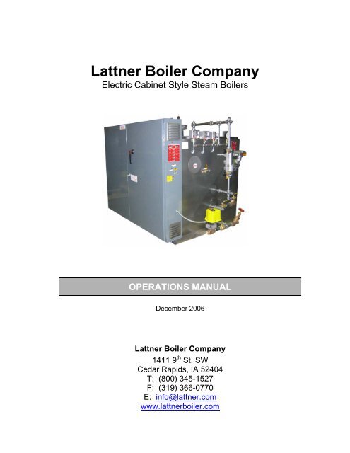
<strong>Lattner</strong> <strong>Boiler</strong> <strong>Company</strong><br />
Electric Cabinet Style Steam <strong>Boiler</strong>s<br />
OPERATIONS MANUAL<br />
December 2006<br />
<strong>Lattner</strong> <strong>Boiler</strong> <strong>Company</strong><br />
1411 9 th St. SW<br />
Cedar Rapids, IA 52404<br />
T: (800) 345-1527<br />
F: (319) 366-0770<br />
E: info@lattner.com<br />
www.lattnerboiler.com
LATTNER BOILER COMPANY<br />
Electric Cabinet Style Steam <strong>Boiler</strong>s<br />
Index<br />
Page 1<br />
______________________________________________________________________________________________________________________________<br />
Index<br />
Section I: General Description Page 2<br />
1. <strong>Boiler</strong> Design ………………………………………………………………………………………………2<br />
2. <strong>Boiler</strong> Connections ………………………………………………………………………………………….2<br />
3. <strong>Boiler</strong> Trim …………………………………………………………………………………………………...3<br />
4. Control Panel ……..………………………………………………………………………………………...3<br />
5. Factory Tests ..………………………………………………………………………………………………4<br />
6. Nameplates & Stamping …………..………………………………………………………………………..4<br />
7. Guarantees ….………………………………………………………………………………………………4<br />
Section II: Installation Page 5<br />
1. Illustration …………………………………………………………………………………………………….5<br />
2. Unloading …………………………………………………………………………………………………..6<br />
3. Rigging ………………………………………………………………………………………………..……..6<br />
4. Placement of <strong>Boiler</strong> ………………………………………………………………………………………….6<br />
5. Steam Outlet ……...………………………………………………………………………………………....6<br />
6. Blowdown Piping ……………………………………………………………………………………………7<br />
7. Safety Valve ……………………………………………………………………………….………..………9<br />
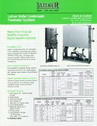
8. <strong>Boiler</strong> Feed Systems ………………………………………..…………………………….……………..…9<br />
9. Electrical Connections …………………………………..……………………………….………………11<br />
10. Before Starting the <strong>Boiler</strong> ………………………………..……………………………….………………11<br />
11. Pressuretrols: Controller & Limit ……………………………………………………………………….12<br />
12. Starting the <strong>Boiler</strong> ………………………………………………………………...……….………………14<br />
13. Boil-Out Recommendations for New <strong>Lattner</strong> <strong>Boiler</strong>s ………………………………………………….14<br />
14. Water Quality Limits for <strong>Lattner</strong> Steam <strong>Boiler</strong>s …………………………………………………………15<br />
Section III: <strong>Boiler</strong> Care & Maintenance Page 16<br />
1. Routine Maintenance …..…………………………………...…………………………………………….16<br />
2. Monthly Procedures ….…………………………………….…………………………………………….16<br />
3. Quarterly Procedures …..………………………………………………………………………………….16<br />
4. Yearly Procedures ……………………………………………………….……………………………….16<br />
5. Heating Elements …..…………………………………………………….……………………………….16<br />
6. Sight Glass Removal & Installation ………………………………………………………………………17<br />
7. McDonnell Miller Servicing ……………………………………………………………………………….18<br />
8. Warrick Relay Replacement ……………………………………………………………………………..19<br />
9. Auxiliary Low Water Cut-Off Probe Cleaning ..…………………………………………………………20<br />
Section IV: Troubleshooting Page 21<br />
1. Troubleshooting ……………………………………………………………………………...…………….21<br />
<strong>Lattner</strong> Warranty & Standard Terms and Conditions Page 22<br />
Additional Product Literature & Burner Manual Page 24<br />
______________________________________________________________________________________________________________________________<br />
<strong>Lattner</strong> <strong>Boiler</strong> <strong>Company</strong><br />
1411 9 th St. SW<br />
Cedar Rapids, IA 52404<br />
Telephone: (800) 345-1527<br />
Fax: (319) 366-0770<br />
Web: www.lattnerboiler.com
LATTNER BOILER COMPANY<br />
Electric Cabinet Style Steam <strong>Boiler</strong>s<br />
Section I: General Description<br />
Page 2<br />
______________________________________________________________________________________________________________________________<br />
Section I: General Description<br />
WARNING: All installation procedures must be followed completely by a<br />
competent installer familiar with boilers and boiler accessories.<br />
CAUTION: Read and follow all instructions before installing any boiler<br />
equipment. All cover plates, enclosures and guards must be maintained and<br />
in place at all times, except during maintenance and servicing.<br />
1. <strong>Boiler</strong> Design<br />
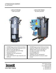
<strong>Lattner</strong> cabinet style electric steam boilers are constructed in accordance to the appropriate ASME Code for<br />
low and high pressure steam boilers. Each boiler includes:<br />
1. Flange mounted, incoloy sheathed heating elements with magnetic contactors;<br />
2. Heavy duty construction of 1/4” or 3/8” steel;<br />
3. 2” therma-fibre insulation and a metal jacket for efficient operation.<br />
4. McDonnell Miller boiler water level and pump controls;<br />
5. Probe-type auxiliary low water cut-off with manual reset;<br />
6. <strong>Boiler</strong> ON/OFF switch;<br />
7. Pressure control switches;<br />
8. Limit switch;<br />
9. Internal circuits sub-divided will all ungrounded circuits fused between contactors and terminals;<br />
10. Blowdown valves for boiler and level controls;<br />
11. Safety valve;<br />
12. Hand and check valves for feed water inlet;<br />
13. Terminals for connection of feed water equipment;<br />
14. Hydrostatic testing of all joints and seams.<br />
2. <strong>Boiler</strong> Connections<br />
2.1. The following items are factory installed in accordance with the ASME Code:<br />
2.1.1. Steam Connection<br />
The supply connection is located on the top centerline of the boiler and is a threaded<br />
design. The operating and design pressure of the boiler, in accordance with the ASME<br />
Code, determines the pressure rating of the valve to be used for the main steam line.<br />
2.1.2. <strong>Boiler</strong> Blowdown Connection<br />
<strong>Boiler</strong>s have one threaded fitting on the bottom centerline at the middle of the pressure<br />
vessel.<br />
2.1.3. Feedwater Make-Up<br />
______________________________________________________________________________________________________________________________<br />
<strong>Lattner</strong> <strong>Boiler</strong> <strong>Company</strong><br />
1411 9 th St. SW<br />
Cedar Rapids, IA 52404<br />
Telephone: (800) 345-1527<br />
Fax: (319) 366-0770<br />
Web: www.lattnerboiler.com
LATTNER BOILER COMPANY<br />
Electric Cabinet Style Steam <strong>Boiler</strong>s<br />
Section I: General Description<br />
Page 3<br />
______________________________________________________________________________________________________________________________<br />
3. <strong>Boiler</strong> Trim<br />
A tapping is provided on one end of the pressure vessel for connection to make-up water.<br />
The following are factory installed standard trim and control items. Trim items are supplied in accordance<br />
with the ASME Code. Controls are UL listed and comply with ASME requirements.<br />
3.1. Safety Relief Valve(s)<br />
In compliance with the ASME Code, steam boiler pressure relief valves are provided. Size and<br />
quantity determined by the valve setting, valve capacity, and the ASME Code. These are shipped<br />
loose to prevent possible damage during shipment.<br />
3.2. Float Control<br />
Furnished complete with drain valve, minimum of 1 inch equalized piping, and crosses for<br />
inspection and clean-out. This is a dual purpose pump control and low water cut-off device.<br />
3.3. Low Water Cut-Off<br />
To prevent burner operation whenever a low water condition occurs, a single pole double throw<br />
float operated level switch is furnished in the float control. Cut-off is wired in series to the heating<br />
element contactors.<br />
3.4. Pump Control<br />
A single pole single throw float level switch is provided in the float control for ON/OFF operation of a<br />
feedwater make-up pump, starter, or solenoid water valve.<br />
3.5. Auxiliary Low Water Cut-Off<br />
An additional control, separate from the primary low water cut-off control is provided to prevent<br />
burner operation if a low-low water condition exists. This device is an internal probe control located<br />
on the top centerline of the pressure vessel.<br />
3.6. Steam Pressure Gauge<br />
4. Control Panel<br />
3-1/2” dial pressure gauge is furnished as standard. The range of the gauge will be in accordance<br />
with the safety valve setting, based on 1.5 times the valve setting for high-pressure units, and 2<br />
times the design pressure of low-pressure units.<br />
A NEMA 1 enclosed control panel is mounted integral to the boiler or as an independent bracket mounted<br />
unit on the boiler base rail. This panel contains as a minimum the following components:<br />
4.1. <strong>Boiler</strong> ON/OFF Switch<br />
A boiler ON/OFF switch is provided to interrupt control power to the 120-volt control circuit. This<br />
switch does not disconnect the main power source.<br />
4.2. Wiring & Controls<br />
______________________________________________________________________________________________________________________________<br />
<strong>Lattner</strong> <strong>Boiler</strong> <strong>Company</strong><br />
1411 9 th St. SW<br />
Cedar Rapids, IA 52404<br />
Telephone: (800) 345-1527<br />
Fax: (319) 366-0770<br />
Web: www.lattnerboiler.com
LATTNER BOILER COMPANY<br />
Electric Cabinet Style Steam <strong>Boiler</strong>s<br />
Section I: General Description<br />
Page 4<br />
______________________________________________________________________________________________________________________________<br />
5. Factory Tests<br />
Wiring and controls include but are not limited to fuses, contactors, incoming power terminal(s),<br />
auxiliary low water cut-off relay, pump relay, step controller, and other miscellaneous electrical<br />
controls.<br />
All devices and wiring are provided in accordance with the latest UL/NFPA 70 requirements. Each<br />
device is UL listed or recognized and bears the UL label and/or stamp.<br />
5.1. Pressure Vessel<br />
The boiler is subjected to an ASME certified hydrostatic pressure test. This test, in accordance with<br />
the requirements of the ASME Code for Section IV Heating <strong>Boiler</strong>s or Section I Power <strong>Boiler</strong>s, is<br />
supervised by an independent inspection agency, to ensure the pressure vessel meets the<br />
standards of the ASME. Upon acceptance of the test by the independent inspector, the unit is<br />
stamped with the “H” symbol for 15 psi design units and with the "S" or “U” symbol for 150 psi and<br />
greater designs. One copy of the ASME data sheet is provided to the purchaser.<br />
5.2. <strong>Boiler</strong> Piping Hydro (Optional)<br />
As an option, Section I high pressure boilers (“S” stamped), built in accordance with the ASME<br />
Code, can be subjected to an additional hydrostatic pressure test. This test includes the integral<br />
steam and water trim piping and when included, the trim valves.<br />
5.3. Heating Element & Controls<br />
All heating element and boiler controls are checked for circuit continuity after mounting and wiring<br />
the heating element onto the boiler.<br />
6. Nameplates & Stamping<br />
6.1. The National Board of Pressure Vessel Inspectors registration number is stamped on the pressure<br />
vessel with the boiler serial number, year built, maximum boiler output, and maximum steaming<br />
capacity.<br />
7. Guarantees<br />
This information is located on the pressure vessel beneath an inspection plate, near the upper rear<br />
of the boiler. A facsimile nameplate of this data stamping is mounted near or on the front panel of<br />
the boiler.<br />
7.1. Warranty<br />
The complete package is warranted for a period of one (1) year from the date of initial start-up or 18<br />
months from the date of shipment or notice to ship, whichever occurs first. This guarantee does not<br />
include items that are damaged due to circumstances beyond the control of <strong>Lattner</strong> <strong>Boiler</strong><br />
<strong>Company</strong>, carelessness, or neglect. Refer to the <strong>Lattner</strong>’s standard warranty and terms and<br />
conditions documents for more detailed information.<br />
______________________________________________________________________________________________________________________________<br />
<strong>Lattner</strong> <strong>Boiler</strong> <strong>Company</strong><br />
1411 9 th St. SW<br />
Cedar Rapids, IA 52404<br />
Telephone: (800) 345-1527<br />
Fax: (319) 366-0770<br />
Web: www.lattnerboiler.com
LATTNER BOILER COMPANY<br />
Electric Cabinet Style Steam <strong>Boiler</strong>s<br />
Section II: Instructions<br />
Page 5<br />
______________________________________________________________________________________________________________________________<br />
Section II: Instructions<br />
WARNING: All installation procedures must be followed completely by a<br />
competent installer familiar with boilers and boiler accessories.<br />
CAUTION: Read and follow all instructions before installing any boiler<br />
equipment. All cover plates, enclosures and guards must be maintained and<br />
in place at all times, except during maintenance and servicing.<br />
1. Illustration<br />
______________________________________________________________________________________________________________________________<br />
<strong>Lattner</strong> <strong>Boiler</strong> <strong>Company</strong><br />
1411 9 th St. SW<br />
Cedar Rapids, IA 52404<br />
Telephone: (800) 345-1527<br />
Fax: (319) 366-0770<br />
Web: www.lattnerboiler.com
LATTNER BOILER COMPANY<br />
Electric Cabinet Style Steam <strong>Boiler</strong>s<br />
Section II: Instructions<br />
Page 6<br />
______________________________________________________________________________________________________________________________<br />
2. Unloading<br />
The boiler was loaded by <strong>Lattner</strong> (including any accessories) and accepted by the transport company as<br />
undamaged. Before unloading the equipment, determine whether any shipping damage is apparent. Once<br />
the equipment is lifted from the trailer, any damage sustained during transit and not filed with the transport<br />
company will be the responsibility of the rigger or purchaser.<br />
2.1. Lifting<br />
2.2. Forklift<br />
The boiler will arrive secured to a wooden skid/pallet and will include a lifting lug (top of the boiler).<br />
When moving or lifting the unit, DO NOT attach sling around the boiler in an attempt to pull the<br />
boiler.<br />
If lifting with a forklift, extended forks should be used beneath the skid. Care must be taken to<br />
ensure that the boiler sits correctly on the forks such that the unit does not topple. Always note the<br />
weight of the boiler relative to the lifting capacity of the forklift.<br />
2.3. Crane or Boom<br />
3. Rigging<br />
When lifting with a crane or boom, attach the hook to the lifting lug on top of the boiler. DO NOT<br />
attach slings or chains to any part of the boiler, or boiler piping.<br />
Always use a competent rigger that has experience moving and setting boilers. If the unit will be moved<br />
into the permanent location with a forklift, crane, or boom, follow the directions in section 1. However, if<br />
moving the unit through a tight space or into an area that will not permit a forklift, place the boiler on rollers<br />
or on 2 inch pipes and roll the boiler into place. If the unit is dragged, attach chains to the base frame only.<br />
If the entry way is too narrow for the boiler and controls to pass through, removal of the trim and controls<br />
can be executed. One should properly denote all wiring and piping connections and match mark<br />
accordingly for attachment after the boiler is placed. It may be helpful to use a digital camera to record the<br />
location of trim items for reference.<br />
4. Placement of <strong>Boiler</strong><br />
4.1. Floor<br />
5. Steam Outlet<br />
<strong>Boiler</strong> must be placed on a level, noncombustible surface. NEVER install boiler on a wood floor or<br />
any other combustible surface (i.e., carpet, linoleum).<br />
5.1. Pipe Size<br />
Size pipe according to system requirements.<br />
5.2. Outlet Size<br />
Refer to product literature sheet for steam outlet size on a particular boiler model.<br />
______________________________________________________________________________________________________________________________<br />
<strong>Lattner</strong> <strong>Boiler</strong> <strong>Company</strong><br />
1411 9 th St. SW<br />
Cedar Rapids, IA 52404<br />
Telephone: (800) 345-1527<br />
Fax: (319) 366-0770<br />
Web: www.lattnerboiler.com
LATTNER BOILER COMPANY<br />
Electric Cabinet Style Steam <strong>Boiler</strong>s<br />
Section II: Instructions<br />
Page 7<br />
______________________________________________________________________________________________________________________________<br />
5.3. Steam Stop Valve<br />
Install a steam stop valve in the steam line as close to the boiler as is practical. A steam stop valve<br />
allows the boiler to be isolated from the system during service work and may be helpful in throttling<br />
steam flow. Required by ASME Code if the boiler is operated over 15 psi. Valve should be rated<br />
for the maximum design pressure of the boiler.<br />
5.4. Steam Piping<br />
The steam line should be pitched downward slightly away from the boiler, toward a steam trap. If<br />
using a steam solenoid valve, the steam line should slope upward slightly to the solenoid valve.<br />
After the solenoid valve, the steam line should slope downward.<br />
5.5. Codes & Standards<br />
6. Blowdown Piping<br />
Piping must comply with all industry standards (especially ANSI B31.1) and all state and local<br />
codes.<br />
6.1. <strong>Boiler</strong> Bottom Blowdown (See Diagram Below)<br />
6.1.1. DO NOT REDUCE. Blowdown piping and all fittings must be the same size as the boiler<br />
blowdown connection (refer to product literature sheets).<br />
6.1.2. Low pressure boilers, operating at 15 psi or less, require one blowdown or drain valve. The<br />
pressure rating of the valve must be equal to or greater than the pressure of the boiler but<br />
not lower than 30 psi.<br />
6.1.3. <strong>Boiler</strong>s operating 16 psi to 100 psi require a single blowdown valve. A Y-type or a ball<br />
valve is acceptable.<br />
6.1.4. <strong>Boiler</strong>s operating 101 psi to 150 psi require piping designed for a pressure of 125% of the<br />
boiler safety valve set pressure (schedule 80 blowdown piping), one slow opening valve<br />
______________________________________________________________________________________________________________________________<br />
<strong>Lattner</strong> <strong>Boiler</strong> <strong>Company</strong><br />
1411 9 th St. SW<br />
Cedar Rapids, IA 52404<br />
Telephone: (800) 345-1527<br />
Fax: (319) 366-0770<br />
Web: www.lattnerboiler.com
LATTNER BOILER COMPANY<br />
Electric Cabinet Style Steam <strong>Boiler</strong>s<br />
Section II: Instructions<br />
Page 8<br />
______________________________________________________________________________________________________________________________<br />
and one quick opening blowdown valve. If cast iron, these valves must be class 250. If<br />
steel, these valves must be class 150, or if bronze, a WSP rating of at least 200.<br />
6.1.5. Standard globe and gate valves that form a pocket inside the valve are not acceptable<br />
blowdown valves. Y-type and ball valves are acceptable blowdown valves.<br />
6.1.6. All blowdown piping must meet ANSI B31.1 code and all city and state codes.<br />
6.1.7. Galvanized piping is not acceptable for boiler blowdown piping.<br />
6.2. Automatic Bottom Blowdown<br />
A <strong>Lattner</strong> automatic bottom blowdown valve may be used in place of one of the manual blowdown<br />
valves.<br />
6.3. Water Level Control Drain Valve<br />
A water column type level control is supplied with one drain valve. Connect the control drain line<br />
into the bottom blowdown line after the second bottom blowdown valve.<br />
6.4. Blowdown Discharge<br />
All boiler blowdown water must be discharged to a safe location, specifically to a blowdown<br />
separator.<br />
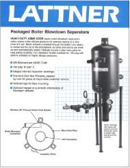
6.5. Blowdown Separator<br />
Select a <strong>Lattner</strong> blowdown separator according to the size of the boiler blowdown connection:<br />
¾ or 1 inch Model 810<br />
Up to 1-1/2 inches Model 1450<br />
6.6. Blowdown Separator Inspection Opening<br />
The extra coupling in the separator vessel is an inspection opening. The inspection opening will be<br />
plugged.<br />
6.7. Blowdown Separator Vent<br />
The blowdown separator must be vented to atmosp<strong>here</strong>. Vent pipe must discharge outside through<br />
the roof. DO NOT reduce the vent pipe size. DO NOT connect the vent pipe from the condensate<br />
tank to the separator vent unless absolutely necessary.<br />
6.8. Blowdown Separator Drain<br />
The water leaving the separator through the drain should be piped to the sewer. Some codes<br />
require the water to pass through an air gap before entering the sewer.<br />
6.9. Aftercooler<br />
If the water must be cooled before entering the sewer (required by some city and/or state codes),<br />
then an aftercooler must be used. The aftercooler attaches to the blowdown separator drain<br />
______________________________________________________________________________________________________________________________<br />
<strong>Lattner</strong> <strong>Boiler</strong> <strong>Company</strong><br />
1411 9 th St. SW<br />
Cedar Rapids, IA 52404<br />
Telephone: (800) 345-1527<br />
Fax: (319) 366-0770<br />
Web: www.lattnerboiler.com
LATTNER BOILER COMPANY<br />
Electric Cabinet Style Steam <strong>Boiler</strong>s<br />
Section II: Instructions<br />
Page 9<br />
______________________________________________________________________________________________________________________________<br />
connection and mixes cold water with the hot drain water. Units may be either manual or<br />
automatic. Select the aftercooler according to blowdown separator drain size.<br />
205A (auto) or 205M (manual) Model 810<br />
301A (auto) or 301M (manual) Model 1450<br />
6.10. Cooling Water Supply<br />
Connect cold water supply pipe to aftercooler:<br />
205A (auto) or 205M (manual) 1/2 inch NPT<br />
301A (auto) or 301M (manual) 1 inch NPT<br />
6.11. Dead <strong>Boiler</strong> Drain Valve<br />
For draining the boiler when it is cool and not under pressure, the entire drain line must be lower<br />
than the bottom of the boiler. Pipe to sewer or floor drain. Valve must be rated up to the maximum<br />
allowable working pressure of the boiler.<br />
6.12. Codes & Standards<br />
7. Safety Valve<br />
All blowdown piping, drain and sewer connections, water piping and separator connections must be<br />
done in strict compliance with all applicable codes.<br />
7.1. Installation<br />
Be sure safety valve is threaded securely into the boiler or into the boiler. The safety valve will<br />
always be installed in the upright position.<br />
7.2. Discharge<br />
Pipe the safety valve outlet to a safe point of discharge. DO NOT reduce the safety valve<br />
discharge piping. NEVER plug the safety valve outlet.<br />
7.3. Supports<br />
Safety valve piping should be secured by clamps or braces to a wall or structural member. Do not<br />
allow the discharge piping to hang on the safety valve.<br />
7.4. Codes & Standards<br />
8. <strong>Boiler</strong> Feed Systems<br />
All safety valve piping and supports must conform to all applicable codes.<br />
8.1. Condensate Return Systems<br />
8.1.1. Make-Up Water Supply<br />
Connect city water line to the float valve with the boiler feed system. Install a manual shut-<br />
______________________________________________________________________________________________________________________________<br />
<strong>Lattner</strong> <strong>Boiler</strong> <strong>Company</strong><br />
1411 9 th St. SW<br />
Cedar Rapids, IA 52404<br />
Telephone: (800) 345-1527<br />
Fax: (319) 366-0770<br />
Web: www.lattnerboiler.com
LATTNER BOILER COMPANY<br />
Electric Cabinet Style Steam <strong>Boiler</strong>s<br />
Section II: Instructions<br />
Page 10<br />
______________________________________________________________________________________________________________________________<br />
off valve in the water line.<br />
LV8 through LV35 1/2 inch NPT<br />
LV60 through LV100 3/4 inch NPT<br />
8.1.2. Pump Suction Line<br />
This is pre-piped from the factory with an isolation valve and strainer.<br />
8.1.3. Pump Discharge Line<br />
DO NOT reduce. Use 1 or 1-1/4 inch NPT pipe and fittings between pump and boiler.<br />
Install two spring-loaded check valves. Install a hand shut-off valve between the last<br />
check valve and the boiler. Keep the number of elbows and fittings to a minimum.<br />
8.1.4. Condensate Return Line<br />
Condensate from all steam traps should be tied into a common return line. The<br />
condensate return line should be pitched downward toward the condensate return tank.<br />
8.1.5. Condensate Return System Vent<br />
Condensate return tank must be properly vented to atmosp<strong>here</strong>. Vent should discharge<br />
through the roof or through a wall to the outside. DO NOT reduce the vent pipe size.<br />
LV8 through LV35 1 inch NPT<br />
LV60 1-1/4 inch NPT<br />
LV75 1-1/2 inch NPT<br />
LV100 2-1/2 inch NPT<br />
8.1.6. Condensate Return System Overflow<br />
Pipe to floor drain. Overflow connection should be at least as large as the condensate<br />
return.<br />
8.1.7. Condensate Return System Drain Connection<br />
8.2. Solenoid Water Valve<br />
Pipe to floor drain. Install a valve in the line. 1 inch NPT line is sufficient.<br />
8.2.1. Water Pressure<br />
This system will work only if the water supply pressure is at least 10 psi higher than the<br />
boiler operating pressure.<br />
8.2.2. Water Inlet<br />
8.2.3. Piping<br />
Refer to the boiler assembly print for correct connection and location of the feedwater inlet.<br />
______________________________________________________________________________________________________________________________<br />
<strong>Lattner</strong> <strong>Boiler</strong> <strong>Company</strong><br />
1411 9 th St. SW<br />
Cedar Rapids, IA 52404<br />
Telephone: (800) 345-1527<br />
Fax: (319) 366-0770<br />
Web: www.lattnerboiler.com
LATTNER BOILER COMPANY<br />
Electric Cabinet Style Steam <strong>Boiler</strong>s<br />
Section II: Instructions<br />
Page 11<br />
______________________________________________________________________________________________________________________________<br />
The solenoid water valve assembly will be piped in the following order: Y-type strainer,<br />
solenoid valve, spring-loaded check valve, globe valve, and boiler. All pipe is 1/2 inch NPT.<br />
8.2.4. Water Supply<br />
9. Electrical Connections<br />
Connect water supply to the strainer.<br />
CAUTION: All electrical work shall be done by a competent electrician. All wiring must be done in strict<br />
accordance with the National Electrical Code and any state or local codes.<br />
9.1. Reconnecting Controls<br />
If the boiler was shipped with controls removed, re-connect the wires according to the wiring<br />
diagram. All wires that need to be reconnected will have a tag indicating the control or terminals to<br />
which they must be connected.<br />
9.2. Electrical Supply (See wiring diagram unique to boiler supplied for voltage requirements)<br />
9.2.1. Connect incoming power supply from a fused disconnect or circuit breaker to the incoming<br />
terminal blocks in the boiler panel.<br />
9.2.2. Supply 120 volt single phase from a separate fused disconnect. Use a 15 amp circuit<br />
breaker or fused disconnect if the boiler has a solenoid water feed valve or a pump motor<br />
1/2 hp or less or a motor starter for a three phase pump. Use a 20 amp circuit breaker or<br />
fused disconnect if the boiler has a 3/4 hp pump motor, 120 volt single phase.<br />
9.2.3. If boiler has a control circuit transformer, t<strong>here</strong> is no need for a separate 120 volt power<br />
source.<br />
9.3. Wiring Water Feed System<br />
Wire the solenoid water valve, boiler feed pump or pump motor starter as indicated on the wiring<br />
diagram.<br />
10. Before Starting the <strong>Boiler</strong><br />
10.1. Spare Fittings<br />
Check that all unused pipe nipples are plugged or capped.<br />
10.2. Float Block<br />
Remove the float block screwed into the body of the McDonnell Miller level control. Replace with a<br />
malleable iron plug (supplied with the boiler).<br />
10.3. Condensate Return System<br />
Make sure t<strong>here</strong> is make-up water supply to the tank. Make sure t<strong>here</strong> is water in the tank.<br />
10.4. Turn Pump Switch “ON”<br />
______________________________________________________________________________________________________________________________<br />
<strong>Lattner</strong> <strong>Boiler</strong> <strong>Company</strong><br />
1411 9 th St. SW<br />
Cedar Rapids, IA 52404<br />
Telephone: (800) 345-1527<br />
Fax: (319) 366-0770<br />
Web: www.lattnerboiler.com
LATTNER BOILER COMPANY<br />
Electric Cabinet Style Steam <strong>Boiler</strong>s<br />
Section II: Instructions<br />
Page 12<br />
______________________________________________________________________________________________________________________________<br />
Turn on the pump switch. Pump or solenoid valve should start immediately. If not, see the<br />
troubleshooting section of this manual.<br />
10.5. Check for Leaks<br />
While the boiler is filling, check for leaks in the piping and around the boiler. If t<strong>here</strong> are leaks, turn<br />
off the pump switch and fix all leaks before continuing.<br />
11. Pressuretrols: Controller and Limit (See Diagram Below)<br />
11.1. Standard<br />
All <strong>Lattner</strong> boilers will have at least two pressure switches, a “controller” and a “limit”.<br />
11.2. Controller<br />
Before the boiler is started, the steam pressure is 0 psi. At this point, the controller is in the "on"<br />
condition and is calling for heat. When the boiler switch is turned on, the boiler will start generating<br />
steam. As the boiler warms, the steam pressure will rise. When the steam pressure reaches the<br />
controller's set point, the controller will shut off the burner. As steam is used, the pressure will<br />
begin to drop. When steam pressure drops enough, the controller will start the heating element<br />
again. The controller will continue to operate in this manner to maintain boiler pressure.<br />
11.2.1. Controller (See Pressuretrol Diagram on Page 12)<br />
On the left side of the pressuretrol is the set point indicating scale labeled "MAIN". Turn the<br />
main scale adjustment screw until the set point indicator aligns with the desired operating<br />
______________________________________________________________________________________________________________________________<br />
<strong>Lattner</strong> <strong>Boiler</strong> <strong>Company</strong><br />
1411 9 th St. SW<br />
Cedar Rapids, IA 52404<br />
Telephone: (800) 345-1527<br />
Fax: (319) 366-0770<br />
Web: www.lattnerboiler.com
LATTNER BOILER COMPANY<br />
Electric Cabinet Style Steam <strong>Boiler</strong>s<br />
Section II: Instructions<br />
Page 13<br />
______________________________________________________________________________________________________________________________<br />
pressure. Turn screw clockwise to increase pressure, counterclockwise to decrease<br />
pressure.<br />
11.2.2. Differential<br />
When the boiler pressure reaches the set point the controller shuts off the heating element.<br />
The pressure must drop by a set amount before the controller will turn on the heating<br />
element again. That amount is called the differential. The differential is adjustable.<br />
11.2.3. Setting the Differential (See Pressuretrol Diagram on Page 12)<br />
On the far left side of the pressuretrols is the differential indicating scale labeled "DIFF".<br />
Turn the differential adjusting screw until the indicator aligns with the desired differential. A<br />
minimum differential will maintain the boiler pressure closer to the set point. A larger<br />
differential will help prevent rapid on and off cycling of the boiler, but may cause unwanted<br />
pressure drops before restarting.<br />
11.3. Modulating Controller (Optional)<br />
11.4. Limit<br />
An optional modulating pressure controller may be supplied with boiler. Modulating pressure<br />
controller with potentiometer is controlled by a sequence or step controller for boilers with multiple<br />
stages. (See controller and sequencer/step controller manuals for additional information).<br />
The limit switch is similar in operation to the controller but has a slightly higher set point. If the<br />
controller fails to shut off the boiler and the steam pressure continues to rise, the limit switch will<br />
shut down the boiler. The controller is an operating switch; the limit serves as an auxiliary safety<br />
cut-off. The limit switch is supplied with a manual reset function. If the steam pressure trips the<br />
high limit switch, the limit locks in the off position. The limit switch will not reset until the manual<br />
reset lever is pressed. Mercury switch limits have reset buttons on top. Snap switch limits have<br />
reset buttons on front.<br />
11.4.1. Setting the Limit<br />
This is done using the same procedure as for the controller. The limit setting will be higher<br />
than the controller's set point. For low pressure boilers (15 psi or less), set the limit switch<br />
1 psi lower than the safety valve setting. For high pressure boilers, set the limit switch at<br />
least 10 psi higher than the controller and 5 psi lower than the safety valve setting.<br />
11.5. Night Operating Pressure Switch<br />
A third pressure switch may be supplied as an option. This switch allows the boiler to operate at<br />
low pressure at night for heating the building. Set the night operating pressure switch at<br />
approximately 10 psi. The boiler panel box will also be wired with a High/Low selector switch.<br />
Setting the selector switch at “Low”, the boiler will operate at 10 psi. When the switch is turned to<br />
“High”, the night operating switch is by-passed and the boiler operates at the normal operating<br />
pressure.<br />
11.6. Example<br />
<strong>Boiler</strong> with a 100 psi safety valve. Set the controller at 80 psi with an 8-10 psi differential. Set the<br />
______________________________________________________________________________________________________________________________<br />
<strong>Lattner</strong> <strong>Boiler</strong> <strong>Company</strong><br />
1411 9 th St. SW<br />
Cedar Rapids, IA 52404<br />
Telephone: (800) 345-1527<br />
Fax: (319) 366-0770<br />
Web: www.lattnerboiler.com
LATTNER BOILER COMPANY<br />
Electric Cabinet Style Steam <strong>Boiler</strong>s<br />
Section II: Instructions<br />
Page 14<br />
______________________________________________________________________________________________________________________________<br />
limit switch at 90 psi. Turn on the boiler, heating element will start. When the steam pressure<br />
reaches 80 psi, the controller shuts down the heating element. When the pressure drops to 70-72<br />
psi the heating element restarts. The boiler continues to cycle to maintain 80 psi. If the steam<br />
pressure rises to 90 psi, the limit switch shuts off the boiler. The manual reset on the limit switch<br />
must then be reset before the boiler will operate again.<br />
For any additional information on the Honeywell Pressuretrols, refer to the Honeywell product sheet<br />
in the back of this manual.<br />
12. After filling the boiler and setting the controls, turn the boiler switch to the ON position. Note: The boiler will<br />
not start until the manual reset buttons for low water and the steam limit are reset. <strong>Boiler</strong> should now<br />
energize.<br />
13. Boil-out recommendations for new <strong>Lattner</strong> boilers<br />
With proper operation and maintenance you can expect years of trouble free service from your new <strong>Lattner</strong><br />
boiler. The procedure for correct operation and care of your unit is not complicated, nor is it time<br />
consuming. In this bulletin, we outline the proper boil-out procedure for you boiler prior to placing it into<br />
service.<br />
If is necessary to clean the inside of the new boiler of oil and grease used as tube rolling lubricants,<br />
threading, and/or other various reasons beyond the manufacturer’s control. Since these coatings may lower<br />
the heat transfer rate of the heating surfaces, failure to remove these coatings will result in your unit<br />
foaming, priming, carry-over or other damage. The boil-out operation is easily accomplished by following<br />
the procedure as outlined below:<br />
13.1. Fill the boiler to the normal water line.<br />
13.2. Close boiler steam stop valve in the steam line.<br />
13.3. Remove safety valves at the top of the boiler. The safety valves must be removed to prevent any<br />
contaminants or boil-out solution from entering them.<br />
13.4. Tri-sodium phosphate and caustic soda each in the amount of one pound per 50 gallons of water<br />
are the suggested chemicals for cleaning boilers. Dissolve these compounds in water and add<br />
dissolved chemicals through an opening at the top of the boiler.<br />
NOTE: When dissolving and mixing the boil-out chemicals, the use of a suitable face mask,<br />
goggles, rubber gloves, and protective clothing is mandatory. DO NOT permit the dry chemicals or<br />
the concentrated solution to come in contact with skin or clothing.<br />
13.5. After adding the boil-out solution, add water to the boiler until it is completely filled.<br />
13.6. Operate the boiler intermittently for 1 hour. Maintain just enough heat to hold the solution at the<br />
boiling point. Be patient.<br />
13.7. Continue the process until the overflow water appears clear.<br />
13.8. Stop the heating element and allow the water to cool to about 120°F. Drain the boiler while the<br />
water is still warm.<br />
NOTE: Prior to draining the boiler, check with local water treatment facilities to determine whether<br />
special instructions or permits are required to dispose of the water.<br />
______________________________________________________________________________________________________________________________<br />
<strong>Lattner</strong> <strong>Boiler</strong> <strong>Company</strong><br />
1411 9 th St. SW<br />
Cedar Rapids, IA 52404<br />
Telephone: (800) 345-1527<br />
Fax: (319) 366-0770<br />
Web: www.lattnerboiler.com
LATTNER BOILER COMPANY<br />
Electric Cabinet Style Steam <strong>Boiler</strong>s<br />
Section II: Instructions<br />
Page 15<br />
______________________________________________________________________________________________________________________________<br />
13.9. After closing the openings and reinstalling the safety valves, fill the boiler to its normal water level<br />
and fire it until the water temperature is at least 180°F to drive off any dissolves gasses and oxygen<br />
which might otherwise corrode the metal.<br />
On a steam system, the condensate should be wasted until test show the elimination of undesirable<br />
impurities. During the period the condensate is wasted, attention must be given to the treatment of<br />
the raw water used as make up so that an accumulation of unwanted materials or corrosion does<br />
not occur. Follow the advice of your water treatment company.<br />
14. Water Quality Limits for <strong>Lattner</strong> Steam <strong>Boiler</strong>s<br />
Constituent Recommended Value or Limit<br />
Oxygen 0 parts per million<br />
Carbon Dioxide 0 parts per million<br />
pH 9.0 to 10.0<br />
Total Hardness 1 parts per million as CaCO3<br />
Total Alkalinity 600 parts per million as CaCO3<br />
Total Dissolved Solids 2200 to 2500 parts per million<br />
Total Iron
LATTNER BOILER COMPANY<br />
Electric Cabinet Style Steam <strong>Boiler</strong>s<br />
Section III: <strong>Boiler</strong> Care & Maintenance<br />
Page 16<br />
______________________________________________________________________________________________________________________________<br />
Section III: <strong>Boiler</strong> Care & Maintenance<br />
WARNING: All maintenance procedures must be performed by competent<br />
personnel familiar with boilers and boiler accessories.<br />
CAUTION: Always disconnect main power before attempting<br />
to service equipment.<br />
NOTE: Certain maintenance items concerning specific components may be<br />
found in the product literature specifications of this manual.<br />
1. Routine Maintenance<br />
1.1. Make visual check of all controls.<br />
1.2. Check for buzzing contactors in control panel. Clean or replace if necessary.<br />
1.3. Observe pressure gauge for normal operation.<br />
1.4. Inspect for water or steam leaks at piping connections and at tube bundle end.<br />
2. Monthly Procedures<br />
2.1. Inspect all wiring in control panels and check for tightness.<br />
2.2. Check all piping connections and fittings for tightness.<br />
3. Quarterly Procedures<br />
3.1. Check low water cut-off for proper operating and for possible clogging.<br />
3.2. Check all other valves and controls for proper operation. Replace defective parts immediately.<br />
4. Yearly Procedures<br />
4.1. Shut down entire boiler and conduct complete inspection.<br />
4.2. Replace any defective heating elements which may have been plugged.<br />
4.3. Inspect heating elements for scale. If scale has formed, clean with a commercially available<br />
descaling compound suitable for use with incoloy elements (Ni, Cr, Fe), such as OAKITE DRYCID.<br />
5. Heating Elements<br />
5.1. If a bad heating element is detected, remove that element from service. To perform this task, follow<br />
the steps below:<br />
5.1.1. Turn of all power sources.<br />
5.1.2. Drain boiler.<br />
______________________________________________________________________________________________________________________________<br />
<strong>Lattner</strong> <strong>Boiler</strong> <strong>Company</strong><br />
1411 9 th St. SW<br />
Cedar Rapids, IA 52404<br />
Telephone: (800) 345-1527<br />
Fax: (319) 366-0770<br />
Web: www.lattnerboiler.com
LATTNER BOILER COMPANY<br />
Electric Cabinet Style Steam <strong>Boiler</strong>s<br />
Section III: <strong>Boiler</strong> Care & Maintenance<br />
Page 17<br />
______________________________________________________________________________________________________________________________<br />
5.1.3. Disconnect wiring from the defective element and tape ring connectors with electrical<br />
insulating tape.<br />
5.1.4. Remove both retaining nuts.<br />
5.1.5. Pull element out approximately 6” and cut off with hacksaw.<br />
5.1.6. Push element back into vessel.<br />
5.1.7. Insert a short piece of 7/16” diameter round rod (approximately 2” to 3” long) in place of the<br />
element, and using a new compression sleeve and the old retaining nut, tighten the rod into<br />
place.<br />
5.1.8. At the next scheduled maintenance shut down, replace all defective elements with new<br />
ones by removing flange assembly.<br />
5.2. To replace heating element flange assembly, proceed as follows:<br />
5.2.1. Turn off all power sources.<br />
5.2.2. Drain the boiler.<br />
5.2.3. Disconnect element leads, making sure to mark them for reconnection.<br />
5.2.4. Remove flange bolts and entire heating flange.<br />
5.2.5. Clean matching flange on boiler and remove all traces of old gasket.<br />
5.2.6. Use new gasket and apply gasket compound to both sides.<br />
5.2.7. Align flange in same concentric position as before (top is marked).<br />
5.2.8. Tighten flange bolts and rewire using wiring diagram and element layout drawing as<br />
reference.<br />
5.2.9. Make sure all terminals are clean and bright and that nuts are tightened to at least 25 inchlbs.<br />
of torque. DO NOT over tighten.<br />
5.2.10. Before boiler is put back intro service, check all bolts and electrical fitting for tight<br />
connections.<br />
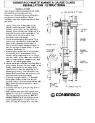
6. Sight Glass Removal & Installation (See Diagram Below)<br />
6.1. <strong>Boiler</strong> and pump should be switched off.<br />
6.2. <strong>Boiler</strong> should be cool and the water level should be below the lower water gauge fixture.<br />
6.3. Close the upper and lower water gauge valves.<br />
6.4. Loosen both sight glass packing nuts (top and bottom) with a wrench.<br />
6.5. Slide glass carefully upward into the upper fixture. Glass should lift out of the lower fixture.<br />
______________________________________________________________________________________________________________________________<br />
<strong>Lattner</strong> <strong>Boiler</strong> <strong>Company</strong><br />
1411 9 th St. SW<br />
Cedar Rapids, IA 52404<br />
Telephone: (800) 345-1527<br />
Fax: (319) 366-0770<br />
Web: www.lattnerboiler.com
LATTNER BOILER COMPANY<br />
Electric Cabinet Style Steam <strong>Boiler</strong>s<br />
Section III: <strong>Boiler</strong> Care & Maintenance<br />
Page 18<br />
______________________________________________________________________________________________________________________________<br />
6.6. Pull glass down, out of the upper fixture tilting the glass slightly to clear the lower fixture. Be careful<br />
not to break the sight glass when removing.<br />
6.7. Assemble the new sight glass (as shown above). ALWAYS replace the gaskets and brass<br />
washers when installing a new sight glass.<br />
6.8. Slide the new glass into the upper fixture. Glass should clear the lower fixture and tilt into position.<br />
6.9. Slide the sight glass down into the lower fixture. Equalize the gap between the upper and lower<br />
fixtures.<br />
6.10. Tighten the sight glass packing nuts hand tight.<br />
6.11. Use a wrench to tighten 1/4 turn past hand tight. NEVER over tighten the sight glass. This will<br />
crack the glass and cause it to shatter under pressure.<br />
6.12. Open the upper and lower gauge valves.<br />
6.13. Switch on boiler and pump.<br />
7. McDonnell Miller Servicing (See Diagram Below)<br />
7.1. Disconnect all power to the boiler.<br />
7.2. The boiler should be cool and drained of all water just below the McDonnell Miller control.<br />
7.3. Make sure all water is drained from the McDonnell Miller control by opening the control blowdown<br />
valve.<br />
______________________________________________________________________________________________________________________________<br />
<strong>Lattner</strong> <strong>Boiler</strong> <strong>Company</strong><br />
1411 9 th St. SW<br />
Cedar Rapids, IA 52404<br />
Telephone: (800) 345-1527<br />
Fax: (319) 366-0770<br />
Web: www.lattnerboiler.com
LATTNER BOILER COMPANY<br />
Electric Cabinet Style Steam <strong>Boiler</strong>s<br />
Section III: <strong>Boiler</strong> Care & Maintenance<br />
Page 19<br />
______________________________________________________________________________________________________________________________<br />
7.4. Disconnect the wiring and conduit connection to the McDonnell Miller. Tag all wires to ensure they<br />
are reconnected properly.<br />
7.5. Remove the eight bolts holding the operating mechanism to the McDonnell Miller body. Use a<br />
9/16" wrench or a crescent wrench.<br />
7.6. It may be necessary to tap near the base of the operating mechanism to free it from the body.<br />
7.7. Lift the McDonnell Miller operating mechanism out of the body. Be careful to avoid damaging the<br />
float and float arm which extend into the body of the McDonnell Miller.<br />
7.8. Carefully scrape the old gasket from the body and the operating mechanism of the McDonnell<br />
Miller.<br />
7.9. Remove any scale in the McDonnell Miller body. Always check the operating mechanism for any<br />
scale that might be blocking the float or float arm.<br />
7.10. Check the float for any holes.<br />
7.11. Hold the float submerged in a bucket of water and look for any air bubbles coming from the float.<br />
7.12. Always reassemble the McDonnell Miller operating mechanism to the body with a new gasket.<br />
7.13. Reinstall the eight bolts to the operating mechanism. Draw up the bolts evenly to prevent damage<br />
to the gasket, body or operating mechanism. Do not over tighten the bolts.<br />
7.14. Reconnect the McDonnell Miller per wiring diagram.<br />
7.15. Reconnect all power to the boiler.<br />
8. Warrick Relay Replacement<br />
8.1. Disconnect all power to the boiler.<br />
8.2. Pull relay out by hand. This may take a little force but be careful.<br />
______________________________________________________________________________________________________________________________<br />
<strong>Lattner</strong> <strong>Boiler</strong> <strong>Company</strong><br />
1411 9 th St. SW<br />
Cedar Rapids, IA 52404<br />
Telephone: (800) 345-1527<br />
Fax: (319) 366-0770<br />
Web: www.lattnerboiler.com
LATTNER BOILER COMPANY<br />
Electric Cabinet Style Steam <strong>Boiler</strong>s<br />
Section III: <strong>Boiler</strong> Care & Maintenance<br />
Page 20<br />
______________________________________________________________________________________________________________________________<br />
8.3. Replace the Warrick with a new 26M series Warrick. The relay has a small tab so that it can be<br />
installed only one way.<br />
8.4. Reconnect the power to the boiler.<br />
9. Auxiliary Low Water Cut-Off Probe Cleaning (See Diagram Below)<br />
9.1.1. Disconnect all power to the boiler.<br />
9.1.2. Remove the four screws on top of the probe enclosure with a Phillips screwdriver.<br />
9.1.3. Remove the wire from the probe using a 5/16" wrench or a crescent wrench. Only the wire on the<br />
probe is to be removed.<br />
9.1.4. Use a 13/16" spark plug socket and remove the probe.<br />
9.1.5. Clean the stainless steel probe and probe fitting.<br />
9.1.6. Reinsert the probe using a 13/16" spark plug socket. Only tighten the probe enough to stop any<br />
steam leaks. Over tightening will destroy the threads of the enclosure.<br />
9.1.7. Reinstall the probe wire to the probe.<br />
9.1.8. Reassemble the cover to the enclosure with the four Phillips screws.<br />
9.1.9. Reconnect power to the boiler.<br />
______________________________________________________________________________________________________________________________<br />
<strong>Lattner</strong> <strong>Boiler</strong> <strong>Company</strong><br />
1411 9 th St. SW<br />
Cedar Rapids, IA 52404<br />
Telephone: (800) 345-1527<br />
Fax: (319) 366-0770<br />
Web: www.lattnerboiler.com
LATTNER BOILER COMPANY<br />
Electric Cabinet Style Steam <strong>Boiler</strong>s<br />
Section IV: Troubleshooting<br />
Page 21<br />
______________________________________________________________________________________________________________________________<br />
Section IV: Troubleshooting<br />
WARNING: All troubleshooting procedures must be followed completely by<br />
competent personnel familiar with electric boilers and accessories.<br />
CAUTION: Read and follow all instructions before troubleshooting any boiler<br />
equipment.<br />
1. Troubleshooting<br />
The chart below is a general chart that shows common problems that may occur in boiler operation. This<br />
chart is only to be used by competent service personnel familiar with <strong>Lattner</strong> boiler equipment and controls.<br />
To us this chart, read down the side of the chart from the problem, then read the right side for possible<br />
causes. The causes are arranged with the most common first. If the problem and/or cause is not on the<br />
chart below, consult a trained boiler service company.<br />
Problem Possible Causes<br />
<strong>Boiler</strong> will not operate.<br />
<strong>Boiler</strong> not generating full power.<br />
1. Fuses may have opened due to electrical short or burned out<br />
elements. Use clamp-on ammeter on each wire to ensure fuse<br />
is passing approximately 80% of its rating.<br />
2. Step controller may be defective. See controller data sheets for<br />
trouble shooting assistance.<br />
3. Control circuit fuses mounted inside panel may have opened.<br />
Replace if defective.<br />
4. Low water cut-off may have opened because of low water level.<br />
Verify water level and refer to manufacturer’s data sheet for<br />
assistance.<br />
1. Check for element failure by measuring current.<br />
2. Check for blown fuses.<br />
3. Replace defective elements (see Section III).<br />
4. Supply voltage may be too low.<br />
5. Verify that line currents in all three phases do not vary more<br />
than 10% from each other.<br />
______________________________________________________________________________________________________________________________<br />
<strong>Lattner</strong> <strong>Boiler</strong> <strong>Company</strong><br />
1411 9 th St. SW<br />
Cedar Rapids, IA 52404<br />
Telephone: (800) 345-1527<br />
Fax: (319) 366-0770<br />
Web: www.lattnerboiler.com
LATTNER BOILER COMPANY<br />
Electric Cabinet Style Steam <strong>Boiler</strong>s<br />
Section IV: Troubleshooting<br />
Page 22<br />
______________________________________________________________________________________________________________________________<br />
<strong>Boiler</strong> and pump switches are<br />
ON, pump does not run, low<br />
water level in boiler.<br />
Pump runs but does not maintain<br />
water level in boiler.<br />
Pump or solenoid overfills the<br />
boiler.<br />
Limit switch always shuts down<br />
boiler.<br />
<strong>Boiler</strong> shuts down with auxiliary<br />
low water cut-off.<br />
Safety valve(s) fail.<br />
1. Circuit breaker tripped or fuse blown.<br />
2. McDonnell Miller piping is plugged.<br />
3. McDonnell Miller float is stuck.<br />
4. McDonnell Miller is wired incorrectly.<br />
5. Pump or solenoid water valve is wired incorrectly.<br />
1. Hand valve between pump and boiler is closed.<br />
2. Bad check valve. Always replace with a spring-loaded check<br />
valve.<br />
3. Bad steam traps.<br />
4. Water temperature is too hot.<br />
5. Strainer is plugged.<br />
6. Pump isolation valve is closed.<br />
7. No water is supplied to the pump.<br />
8. Pump out of adjustment.<br />
1. Solenoid water valve is not seating properly.<br />
2. McDonnell Miller float is operating incorrectly.<br />
3. McDonnell Miller snap switch is malfunctioning.<br />
4. McDonnell Miller is wired incorrectly.<br />
5. Pump is wired incorrectly.<br />
1. Scale build-up inside of the boiler.<br />
2. Operating pressure switch is set higher than limit switch.<br />
3. Operating pressure switch is not operating properly.<br />
1. Pump switch is turned off.<br />
2. Probe wired incorrectly.<br />
3. Auxiliary level control relay wired incorrectly.<br />
4. Probe has scale, dirt, or debris on it.<br />
5. Foaming problem in boiler.<br />
6. Water in boiler is too soft.<br />
7. McDonnell Miller is not operating correctly.<br />
8. Pump is not functioning properly.<br />
9. Bad check valve. Always replace with spring-loaded check<br />
valve.<br />
10. No water supplied to the pump.<br />
11. Probe is out of probe socket.<br />
1. Pressure in boiler exceeds pressure setting of safety valve.<br />
2. Operating and/or limit switch set higher than safety valve.<br />
3. Scale build-up inside boiler.<br />
4. Operating and/or limit switch wired incorrectly.<br />
______________________________________________________________________________________________________________________________<br />
<strong>Lattner</strong> <strong>Boiler</strong> <strong>Company</strong><br />
1411 9 th St. SW<br />
Cedar Rapids, IA 52404<br />
Telephone: (800) 345-1527<br />
Fax: (319) 366-0770<br />
Web: www.lattnerboiler.com
LATTNER BOILER LIMITED WARRANTY<br />
A <strong>Lattner</strong> boiler shell is guaranteed to be constructed in accordance with the ASME Code. An independent ASME<br />
boiler inspector inspects the construction of each boiler and: (1) checks mill test reports on all materials used to<br />
ensure that the chemical and physical analysis of such materials complies with the ASME Code; (2) inspects each<br />
boiler shell during construction to see that workmanship complies with the Code; and (3) witnesses the final<br />
hydrostatic test and then places the ASME stamp on the boiler shell and signs an ASME data report certifying the<br />
boiler is ASME approved.<br />
<strong>Lattner</strong> warrants the boiler and any other equipment of its manufacture to be free from defects in material and<br />
workmanship for one (1) year from the date of shipment from the factory, provided the boiler is operated under the<br />
normal use and service for which it was intended, and only if the boiler has been properly installed by a qualified<br />
technician in accordance with but not limited to ASME, ANSI, and NFPA Codes and applicable local, state, and<br />
national codes.<br />
<strong>Lattner</strong>’s obligation under this Warranty is limited, at <strong>Lattner</strong>’s option, to replacing or repairing any defective part<br />
of the boiler or other equipment it manufactures. No allowance will be made for labor, transportation, or other<br />
charges incurred in the replacement or repair of defective parts. Merchandise not manufactured by the <strong>Company</strong>,<br />
supplied in one piece or in component assemblies, is not covered by the above warranty, but the <strong>Company</strong> will<br />
give the Purchaser the benefit of such adjustment as it can make with the manufacturer of such items.<br />
<strong>Lattner</strong> shall not be liable for special, indirect, or consequential damages. <strong>Lattner</strong> shall not be liable for any loss or<br />
damage resulting, directly or indirectly, from the use or loss of use of the boiler. This exclusion from liability<br />
includes the Purchaser’s expenses for downtime or for making up downtime, damages for which the Purchaser<br />
may be liable to other persons, or damages to property.<br />
The remedies set forth in this Warranty are exclusive, and the liability of <strong>Lattner</strong> with respect to any contract or<br />
sale shall not exceed the cost of repair or replacement of the boiler or other equipment manufactured by <strong>Lattner</strong>.<br />
The above Warranty shall not apply to any boiler or other equipment manufactured by <strong>Lattner</strong> which:<br />
1) has been repaired or altered without <strong>Lattner</strong>’s written consent;<br />
2) has been altered in any way so as, in the judgment of <strong>Lattner</strong>, to adversely affect the stability or<br />
reliability of the boiler;<br />
3) has been subject to improper water treatment, scale, corrosion, misuse, negligence, or accident;<br />
4) has not been operated in accordance with <strong>Lattner</strong>’s printed instructions or specifications;<br />
5) has been operated under conditions more severe than or otherwise exceeding those set forth in the<br />
specifications for such boiler; or<br />
6) has not been properly installed by a qualified technical in accordance with but not limited to ASME,<br />
ANSI and NFPA Codes and all applicable local, state and national codes.<br />
THIS WARRANTY IS EXPRESSLY MADE IN LIEU OF ALL OTHER WARRANTIES, EXPRESS OR IMPLIED.<br />
LATTNER MAKES NO WARRANTY OF MERCHANTABILITY OR OF FITNESS FOR ANY PARTICULAR<br />
PURPOSE.<br />
Purchaser must notify <strong>Lattner</strong> of a breach of Warranty within thirty (30) days after discovery t<strong>here</strong>of, but not later<br />
than the one-year guarantee period; otherwise, such claims shall be deemed waived. No allowance will be<br />
granted for any repairs or alterations made by Purchaser without <strong>Lattner</strong>’s prior verbal or written consent. Items<br />
returned to <strong>Lattner</strong> must be accompanied by a factory-supplied return goods authorization (RGA). Such<br />
authorization may be obtained by calling the factory at 319/366-0778 or by writing to P.O. Box 1527, Cedar<br />
Rapids, IA 52406.<br />
<strong>Lattner</strong> neither assumes nor authorizes any person to assume for it any other liability in connection with the sale<br />
or use of the boiler or other equipment manufactured by <strong>Lattner</strong>, and t<strong>here</strong> are no oral agreements or warranties<br />
collateral to or affecting this Agreement.<br />
LATTNER BOILER COMPANY<br />
Cedar Rapids, IA USA<br />
2-98-06
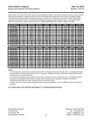
LIMITATION ON QUOTATION<br />
Unless otherwise stated in the quotation, the quotation will remain valid<br />
for a period of thirty (30) days from the date <strong>here</strong>of, at which time it will<br />
automatically expire unless extended by a signed document issued by<br />
the <strong>Company</strong>, from its headquarters in Cedar Rapids, IA.<br />
EQUIPMENT SELECTION<br />
The Purchaser’s selection of sizes, types, capacities, and specifications<br />
and suitability t<strong>here</strong>of for the specific application shall be the unshared<br />
responsibility of the Purchaser or Purchaser’s representative or<br />
consultant.<br />
PERMISSABLE VARIATIONS, STANDARDS, AND TOLERANCES<br />
Except in the particulars specified by the Purchaser and expressly<br />
agreed to in writing by the <strong>Company</strong>, all materials shall be produced in<br />
accordance with the <strong>Company</strong>’s standard practices. The <strong>Company</strong><br />
reserves the right to deviate from tolerances and variations in the<br />
equipment without notice, provided that the substitute part(s) or<br />
deviation(s) are consistent with the usage and performance of the<br />
product.<br />
PRICES<br />
Unless defined otherwise in the quotation, prices are F.O.B. Cedar<br />
Rapids, IA USA, exclusive of freight, storage, off-loading, installation,<br />
service, start-up, extended warranty or local delivery charges, if any.<br />
TAXES<br />
Purchaser shall be liable for all Federal, State, and local taxes with<br />
respect to the purchase of the equipment proposed, unless exclusively<br />
exempted from any taxes and proof t<strong>here</strong>of is on file with the <strong>Company</strong>.<br />
PAYMENT<br />
Purchaser shall pay with US funds, the full amount of the invoiced<br />
purchase price within thirty (30) days of the <strong>Company</strong>’s invoice, whether<br />
the equipment has shipped or has been delayed through no fault of the<br />
<strong>Company</strong> and subject to approved credit. Beginning thirty (30) days after<br />
the invoice date, Purchaser shall pay a late payment charge of two<br />
percent (2%) per month, which is an annual rate of 24%, on any unpaid<br />
portion of the purchase price. The <strong>Company</strong> reserves the right to revoke<br />
or modify these credit terms.<br />
SHIPMENT<br />
Any shipping date shown in the body of the quotation or order<br />
acknowledgement, represents the <strong>Company</strong>’s approximated schedule as<br />
of the date of the quotation, and is subject to change as determined by<br />
shop loading if and when this quotation should be realized as an actual<br />
sale. The <strong>Company</strong> shall not incur any liability of any kind for failure to<br />
ship on any particular date unless a firm shipping date has been<br />
expressly agreed to by an officer of the <strong>Company</strong>, in a separate written<br />
document.<br />
CANCELLATION AND DELAYS<br />
Subsequent to the receipt of Purchaser’s Purchase Order and the<br />
<strong>Company</strong>’s issued order acknowledgement, the Purchaser may not<br />
change or cancel the order in whole or in part without the written<br />
approval and acceptance by the <strong>Company</strong> of such cancellation or<br />
change. The <strong>Company</strong> may condition its approval of a change or<br />
cancellation upon a price change to reflect the <strong>Company</strong>’s cost to<br />
implement the change, or to offset costs incurred by the <strong>Company</strong> in<br />
order preparation, engineering, purchasing, or in actual production of the<br />
order. In the event that the Purchaser delays shipment of the equipment<br />
upon the <strong>Company</strong>’s notice to ship, the equipment shall be placed in<br />
storage at the Purchaser’s risk and expense, and shall be invoiced as if<br />
shipped.<br />
RETURNS AND RESTOCKING<br />
Equipment may be returned to <strong>Lattner</strong> at 1411 9 th Street SW, Cedar<br />
Rapids, IA 52404, only upon prior written authorization of the <strong>Company</strong>.<br />
Consent, if given, will be upon the condition the Purchaser assumes all<br />
carrier charges, responsibility for damages in transit, and a minimum<br />
STANDARD TERMS & CONDITIONS<br />
LATTNER BOILER COMPANY<br />
Cedar Rapids, IA USA<br />
15% restocking charge, and only if the authorized material is in new and<br />
unused condition and returned within one year from original date of<br />
shipment. The credit will be based on the original invoice price or the<br />
current price; whichever is lower, less the applicable restocking charge.<br />
SECURITY INTEREST<br />
For the purposes of securing payment, the <strong>Company</strong> may issue a lien on<br />
the equipment, for past due accounts, until such time that payment has<br />
been received in full. Upon receipt of payment in full, the <strong>Company</strong> will<br />
rescind the lien.<br />
FORCE MAJEURE<br />
In no event shall the <strong>Company</strong> be liable for loss or damage resulting<br />
from any delay or failure to ship or other failure, loss, or damage that is<br />
the proximate result of any act of government authority, revolution, riot,<br />
civil disorder, act of war, delay or default in transportation, inability to<br />
obtain materials or facilities from normal sources, fire, flood, act of God,<br />
or any cause not within the reasonable control of the <strong>Company</strong>. The<br />
<strong>Company</strong> may, without causing a breach or incurring liability, allocate<br />
goods which are in short supply irrespective of the reasons t<strong>here</strong>fore<br />
among customers in any manner which the <strong>Company</strong> in its sole<br />
discretion deems advisable. If an event occurs that is beyond the control<br />
of the <strong>Company</strong>, and that event delays the <strong>Company</strong>’s performance and<br />
causes its cost of production to increase because of the delay, the<br />
<strong>Company</strong> may pass such increased cost(s) on to the Purchaser.<br />
DAMAGE LIMITATION<br />
Under no circumstance shall the <strong>Company</strong> be held liable for any loss of<br />
profits, down time, or any incidental or consequential damages of any<br />
kind with respect to its products or the transaction by which its products<br />
are sold.<br />
WARRANTY AND PERFORMANCE<br />
Products shall be warranted in accordance with the <strong>Company</strong>’s standard<br />
warranty statement, form No. 2-98-R06. The <strong>Company</strong>’s warranty shall<br />
be voided by any abuse, misuse, neglect, unauthorized modification or<br />
service, lack of maintenance and service, or use not in accordance with<br />
the <strong>Company</strong>’s instructions. Warranty shall also be voided if water<br />
treatment has not been provided or by improper start-up of the<br />
equipment. The <strong>Company</strong>’s warranty statement and this paragraph<br />
contain the <strong>Company</strong>’s sole warranty and the <strong>Company</strong> makes no<br />
implied warranty, and t<strong>here</strong> is no implied warranty of merchantability or<br />
fitness for any particular purpose.<br />
SERVICE<br />
Unless otherwise noted <strong>here</strong>in, the cost of the equipment does not<br />
include service or installation. All services performed by the <strong>Company</strong><br />
are subject to the Purchaser’s payment of the <strong>Company</strong>’s prevailing<br />
charges plus necessary travel and living expenses. Whenever service is<br />
quoted, please refer to <strong>Lattner</strong>’s Service Policy for specific details.<br />
EXCLUSION OF OTHER TERMS<br />
This constitutes an offer on behalf of <strong>Lattner</strong> <strong>Boiler</strong> Manufacturing (the<br />
<strong>Company</strong>); to sell the goods described in the quotation, exclusively on<br />
the terms and conditions stated. Acceptance of this by the Purchaser is<br />
<strong>here</strong>by expressly limited to these Terms and Conditions and shall be<br />
applicable to any order issued by the Purchaser unless other terms have<br />
been agreed to in a written document issued by the <strong>Company</strong>.<br />
GOVERNING LAW<br />
The transaction with respect to the goods, which are subject <strong>here</strong>of, shall<br />
be governed by, interpreted, and construed in accordance with the laws<br />
of the State of Iowa. The Courts in the State of Iowa will have the sole<br />
jurisdiction over any claim arising under this contract of sale.<br />
ASSIGNMENT<br />
All sales as evidenced by the <strong>Company</strong>’s acknowledgement shall be<br />
binding upon and insure to the benefit of the Purchaser and the<br />
<strong>Company</strong> and their respective heirs, successors, or assigns.<br />
TC06