operation - Lattner Boiler
operation - Lattner Boiler
operation - Lattner Boiler

You also want an ePaper? Increase the reach of your titles
YUMPU automatically turns print PDFs into web optimized ePapers that Google loves.
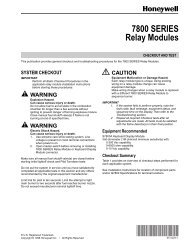
L. Z. • Rev. 3-95 • ©Honeywell Inc. 1995<br />
L404A-D,F; L604A,L,M<br />
Pressuretrol ® Controllers<br />
L404 and L604 Pressuretrol ® Controllers are<br />
line voltage pressure controllers that provide operating<br />
control, automatic limit protection, or manual<br />
reset limit protection for pressure systems of up to<br />
300 psi (21.1 kg/cm 2 or 2068 kpa).<br />
■ Can be used with steam, air, non-combustible gases,<br />
or fluids non-corrosive to the pressure sensing element.<br />
■ Stainless steel diaphragm (except 300 psi [21.1 kg/<br />
cm2 (2068 kPa)] models) also allows use with ammonia,<br />
oxygen, distilled water, and similar media.<br />
■ L404B is recommended for supervision of atomizing<br />
medium pressure in oil burner systems.<br />
■ Models are available with spst, spdt, or dpst switching<br />
and in variety of operating ranges.<br />
■ Dustproof, trouble-free mercury switches (all models<br />
except L404F, which has snap-acting switch).<br />
■ Automatic reset models have adjustable, subtractive<br />
differential (except L604M).<br />
■ Trip-free mechanism on manual reset models assures<br />
that limit function of controller cannot be<br />
defeated by jamming reset lever.<br />
■ Screw adjustments made on top of case.<br />
■ Scaleplates marked in English (psi) and Metric<br />
(kg/cm2 ) units.<br />
■ L404F models available with European enclosure,<br />
British Standard Pipe Threads, ground screw, and<br />
scaleplates marked in kg/cm2 and either psi or kPa.<br />
■ Clear plastic cover on case to observe pressure settings<br />
and switch action.<br />
■ Leveling indicator visible through cover.<br />
■ Hexagonal fitting with 1/4-18 NPT internal threads<br />
for direct mounting to 14026 Steam Trap (siphon<br />
loop).<br />
■ Surface mount is available using screws through<br />
holes (knockouts) in case backing.<br />
CONTENTS<br />
Specifications ................................................ 2<br />
Ordering Information .................................... 2<br />
Installation .................................................... 5<br />
Setting and Checkout..................................... 8<br />
Service Information ..................................... 10<br />
60-2150-10
L404A-D,F; L604A,L,M<br />
SPECIFICATIONS • ORDERING INFORMATION<br />
TRADELINE ® MODELS<br />
TRADELINE ® models are selected and packaged to<br />
provide ease of stocking, ease of handling, and maximum<br />
replacement value. Specifications of TRADELINE ® controls<br />
are the same as those of standard models except as<br />
noted below.<br />
TRADELINE ® MODELS AVAILABLE:<br />
L604A Pressuretrol ® Controllers—Available in 2 to 15, 5 to<br />
50, 10 to 150, and 20 to 300 psi (.14 to 1.1 kg/cm 2 [14 to<br />
103 kPa], .4 to 3.5 kg/cm 2 [34 to 345 kPa], .7 to 10.6 kg/<br />
cm 2 [69 to 1034 kPa], and 1.4 to 21.0 kg/cm 2 [138 to<br />
2068 kPa]) .<br />
ADDITIONAL FEATURES: TRADELINE ® pack with<br />
cross-reference label.<br />
STANDARD MODELS<br />
MODELS: L404A-D,F and L604A,L,M Pressuretrol ® Controllers.<br />
See Table 1. A 14026 Steam Trap (siphon loop)<br />
60-2150—10 2<br />
Specifications<br />
is available, except where noted in Table 1. The steam<br />
trap is necessary for boiler installations.<br />
SWITCH(ES): Mercury switch(es) in all models except the<br />
L404F, which has a Micro Switch snap-acting switch.<br />
PRESSURE SENSING ELEMENT: Stainless steel diaphragm<br />
(brass bellows in 300 psi [21.1 kg/cm 2 ,<br />
(2068 kPa)] models).<br />
MAXIMUM AMBIENT TEMPERATURE: 150°F (66°C).<br />
MINIMUM AMBIENT TEMPERATURE: Minus 35°F<br />
(minus 37°C); also refer to the note in the Location and<br />
Mounting section.<br />
ADJUSTMENT MEANS: Screws on top of controller case.<br />
Scales are marked in psi and kPa.<br />
ELECTRICAL CONNECTIONS: Internal screw terminals;<br />
hole in side of case for 1/2 in. conduit.<br />
MOUNTING MEANS: Hexagonal fitting on diaphragm has<br />
1/4-18 NPT internal threads for mounting on a pipe or<br />
steam trap (siphon loop). Also can be surface-mounted<br />
using screws through two holes (knockouts) in back of<br />
case.<br />
Ordering Information<br />
When purchasing replacement and modernization products from your TRADELINE ® wholesaler or distributor, refer to the Tradeline<br />
Catalog or price sheets for complete ordering number, or specify—<br />
1. Order number (TRADELINE ® model, if desired).<br />
2. Operating range (see Table 1).<br />
3. Model without steam trap, if desired and available (see Table 1, Note b).<br />
4. Optional specifications, if desired (see Table 1).<br />
5. Replacement parts, if desired.<br />
6. Accessories, if desired.<br />
If you have additional questions, need further information, or would like to comment on our products or services, please write or phone:<br />
1. Your local Home and Building Control Sales Office (please check the white pages of your phone directory).<br />
2. Home and Building Control Customer Logistics<br />
Honeywell Inc., 1885 Douglas Drive North<br />
Minneapolis, Minnesota 55422-4386 (612) 951-1000<br />
In Canada—Honeywell Limited/Honeywell Limitée, 740 Ellesmere Road, Scarborough, Ontario M1P2V9. International Sales and<br />
Service Offices in all principal cities of the world. Manufacturing in Australia, Canada, Finland, France, Germany, Japan, Mexico,<br />
Netherlands, Spain, Taiwan, United Kingdom, U.S.A.
L404A-D,F; L604A,L,M<br />
SPECIFICATIONS<br />
DIMENSIONS: See Fig. 1. See Fig. 2 for mounting steam<br />
trap (siphon loop).<br />
WEIGHT: 2 IBC. (0.91 kg).<br />
FINISH: Gray.<br />
APPROVALS:<br />
Underwriters Laboratories Inc. listed (L404A,B,C,D,F;<br />
L604A,L,M only): file no. MP466, vol.10; guide<br />
no. MBPR.<br />
Canadian Standards Association certified (L404A,B,C,D,F;<br />
L604A,L only): file no. LR1620; guide no.400-E-0.<br />
Fig. 1—Mounting dimensions of the L404A,B,C,D,F and L604A,L,M Pressuretrol ® Controllers, in in. (mm).<br />
L404A-D,F; L604A,L,M<br />
1<br />
2<br />
3<br />
1-15/16 (49.2)<br />
3-3/16 (81.0)<br />
1-5/32<br />
(29.4)<br />
2-1/8 (54.0)<br />
4-1/2 (114.3) (COVER)<br />
4-11/32 (110.3) (CASE)<br />
1-61/64 (49.6)<br />
1/4-18 NPT<br />
60-2150—10 4<br />
1<br />
1-13/16<br />
(46.0)<br />
3-7/8<br />
(98.4)<br />
3/16 (4.8) X 21/64 (8.3)<br />
KNOCKOUT (2)<br />
REPLACEMENT PARTS:<br />
129178 Thermoplastic Cover.<br />
14026 Steam Trap (siphon loop)—1/4 in. black iron pipe.<br />
Necessary for boiler installations.<br />
ACCESSORIES:<br />
33312B Knurled Adjustment Knob—with setscrew; fits<br />
on main scale pressure adjusting screw.<br />
4074BWJ Limit Stop Assembly—to limit set point ranges;<br />
includes 129564 Range Stop, 107194 Range Stop<br />
Screw, and 23466 Wrench.<br />
TABLE 2—CONVERSION TABLE (psi to kPa).<br />
Operating Range Subtractive Differential<br />
Scale-Plate Equivalent Scale-Plate Equivalent<br />
(psi) (kg/cm2) (kPa) (psi) (kg/cm2) (kPa)<br />
0 to 15 0 to 10 0 to 103 — — —<br />
2 to 15 .14 to1.0 14 to 103 1 to 6<br />
2 to 6<br />
07 to 4<br />
.14 to .4<br />
7 to 41<br />
14 to 41<br />
5 to 50 .3 to 3.5 34 to 345 4 to 12<br />
5 to 14<br />
.3 to .8<br />
.4 to 1.0<br />
28 to 83<br />
41 to 97<br />
5 to 150 .3 to 10.3 34 to 1034 — — —<br />
10 to 150 .7 to 10.3 69 to 1034 8 to 16<br />
10 to 22<br />
.6 to 1.1<br />
.7 to 1.5<br />
55 to 110<br />
69 to 152<br />
20 to 300 1.4 to 20.7 138 to 2068 15 to 40<br />
20 to 50<br />
1.0 to 2.8<br />
1.4 to 3.5<br />
103 to 276<br />
138 to 345<br />
7/8<br />
(22.2) DIA.<br />
2-3/4 (69.9)<br />
1-3/16 (30.2)<br />
1<br />
1-1/16<br />
(27.0)<br />
13/16<br />
(20.6)<br />
1-1/16<br />
(27.0)<br />
1/2 (12.7)<br />
1-1/2 (38.1)<br />
RESET LEVER (ON MANUAL RESET MODELS ONLY.)<br />
THIS DIMENSION IS 4-27/32 IN. (123.0 MM) ON L604 MODELS WITH A 2 TO 15 PSI (.14 TO 1.0 kg/cm2 (14 TO 103 kPa)) OPERATING RANGE,<br />
AND 5-3/4 IN. (146.A MM) ON L604 MODELS WITH A 20 TO 300 PSI (1.4 TO 20.7 kg/cm2 (138 TO 2068 kPa) OPERATING RANGE.<br />
ONLY ON L604 MODELS WITH A 2 TO 15 PSI (.14 TO 1.0 kg/cm2 (14 TO 103 kPa)) OPERATING RANGE.<br />
3<br />
13/16<br />
(20.6)<br />
3-23/32<br />
(94.5)<br />
4-31/32<br />
(126.2)<br />
2<br />
M8933
WHEN INSTALLING THIS PRODUCT. . .<br />
1. Read these instructions carefully. Failure to follow<br />
them could damage the product or cause a hazardous<br />
condition.<br />
2. Check the ratings given in the instructions and on the<br />
product to make sure the product is suitable for your<br />
application.<br />
3. Installer must be a trained, experienced, flame safeguard<br />
control technician.<br />
4. After installation is complete, check out product<br />
<strong>operation</strong> as provided in these instructions.<br />
CAUTION<br />
1. Disconnect power supply before beginning installation<br />
to prevent possible equipment damage<br />
or electrical shock.<br />
2. When using the controller with a compressor,<br />
install a dampening device (such as a needle valve,<br />
header, or surge tank) to dampen pulsations that<br />
can damage the controller or reduce its life.<br />
IMPORTANT:<br />
1. Locate the controller where the ambient temperature<br />
will not exceed 150°F (66°C).<br />
2. Use pipe compound sparingly to avoid clogging the<br />
hole in the pipe or diaphragm fitting.<br />
3. Do not tighten the controller by hand by holding the case.<br />
4. Accurately level the controller for proper <strong>operation</strong>.<br />
LOCATION AND MOUNTING<br />
NOTE: For most accurate <strong>operation</strong>; add supplemental heat<br />
to installations where the temperature falls below minus<br />
20°F (minus 29°C). Never locate the controller where the<br />
temperature falls below minus 35°F (minus 37°C), because<br />
mercury in the switch freezes at this temperature.<br />
When used with steam boilers, always mount the controller<br />
above the water line in the boiler. A steam trap<br />
(siphon loop) must always be connected between the controller<br />
and the boiler (Fig. 2) to prevent boiler scale and<br />
corrosive vapors from attacking the diaphragm. The loop<br />
on the steam trap must always be perpendicular to the face<br />
of the controller. If the loop is parallel to the controller,<br />
expansion or contraction of the loop tips the controller and<br />
causes the switch to operate inaccurately.<br />
The controller can be mounted (1) alongside the pressure<br />
gauge, (2) in a fitting on the boiler provided by the<br />
manufacturer, (3) at a remote location in case of excessive<br />
vibration, or (4) in a special mounting on a low water<br />
cutoff.<br />
L404A-D,F; L604A,L,M<br />
INSTALLATION<br />
Installation<br />
Fig. 2—Right and wrong mounting of a steam<br />
trap (siphon loop), with approximate dimensions<br />
in in. (mm).<br />
4-1/2 TO 5-1/2<br />
(114.3 TO 139.7)<br />
PRESSUR<br />
CONTROLLER<br />
TEE<br />
BOILER<br />
PRESSURE<br />
GAUGE<br />
14026 1<br />
STEAM TRAP<br />
(SIPHON LOOP)<br />
CORRECT<br />
BOILER<br />
1 1/4 IN. BLACK IRON PIPE WITH 1/4 - 18 NPT EXTERNAL<br />
TRHEADS ON BOTH ENDS. BEND THE STEAM TRAP<br />
(SIPHON LOOP) TO LEVEL THE CONTROLLER.<br />
2-1/4<br />
(57.2)<br />
DIA.<br />
INCORRECT<br />
M8934<br />
Make all pipe connections in accordance with approved<br />
standards. Use only a small amount of pipe compound to<br />
seal the connection joints. Excess pipe compound can clog<br />
the small hole in the fitting and prevent the controller from<br />
operating properly.<br />
To avoid leaks and damage to the case, use a parallel jaw<br />
wrench on the controller’s hexagonal fitting. Do not tighten<br />
the controller by hand by holding the case.<br />
Leveling<br />
A controller with a mercury switch must be accurately<br />
leveled for proper <strong>operation</strong>. It is level when the leveling<br />
indicator (Fig. 11) hangs freely with its pointer directly<br />
over the index mark inside the back of the case. Level the<br />
controller by carefully bending the steam trap (siphon<br />
loop).<br />
Mounting Alongside a Pressure Gauge<br />
To mount the controller alongside a pressure gauge<br />
(Fig. 2), remove the gauge. In its place, install a steam trap<br />
(siphon loop) with a tee on top. Using elbows and pipe<br />
nipples, mount the controller and pressure gauge on the<br />
ends of the tee. Level the controller after installation.<br />
5 60-2150—10
L404A-D,F; L604A,L,M<br />
INSTALLATION<br />
Mounting on a <strong>Boiler</strong><br />
If it is not convenient to mount the controller alongside<br />
the pressure gauge, install a steam trap (siphon loop) in the<br />
fitting provided by the boiler manufacturer. If there is no<br />
fitting, mount the steam trap at a location recommended by<br />
the boiler manufacturer. Screw the controller directly to the<br />
steam trap, and level the controller.<br />
Mounting at a Remote Location<br />
If there is excessive vibration at the boiler that can<br />
adversely affect the <strong>operation</strong> of the controller, mount the<br />
controller at a remote location. All piping from the boiler<br />
must be suitable and solidly mounted. The piping must be<br />
properly pitched to drain all condensation back to the<br />
boiler. A steam trap (siphon loop) must be mounted between<br />
the remote piping and the controller. Level the<br />
controller after installation.<br />
Supervision of Atomizing Medium Pressure<br />
(Air or Steam)—L404B<br />
When air or steam is used as an atomizing medium in an<br />
oil burner system, authorities having jurisdiction (approval<br />
bodies and codes) often require a low limit to prevent<br />
opening the main oil valve until sufficient atomizing pressure<br />
is present, and to shut down the system when the<br />
atomizing pressure falls too low.<br />
The L404B is recommended for this application. It<br />
makes a circuit when the pressure rises to the set point, and<br />
breaks when the pressure falls to the set point minus the<br />
differential (Fig. 10).<br />
WIRING<br />
1. Disconnect the power supply before beginning wiring<br />
to prevent electrical shock or equipment damage.<br />
2. Assume all wiring complies with applicable electrical<br />
codes, ordinances, and regulations. Use NEC Class 1 (line<br />
voltage) wiring.<br />
3. For normal installations, use moisture-resistant No. 14<br />
wire suitable for at least 167°F (75°C) when you are using<br />
the controller with a flame safeguard primary control, or at<br />
least 194°F (90°C) when using it with a programming<br />
control.<br />
4. For high temperature installations, use moisture-resistant<br />
No. 14 wire, selected for a temperature rating above the<br />
maximum operating temperature.<br />
5. All models have a terminal block inside the cover (Fig.<br />
3 and 4) and a 7/8 in. (22.2 mm) hole in one side for 1/2 in.<br />
conduit, cable, or wires. Remove the front cover by loosening<br />
the screw at the bottom of the main scale.<br />
6. Refer to Fig. 5 through 9 for typical hookups. Follow<br />
the burner or boiler manufacturer’s wiring diagram if provided<br />
.<br />
7. Make sure the loads do not exceed the Switch Contact<br />
Ratings in the Specifications section.<br />
8. Replace the front cover when wiring is completed.<br />
60-2150—10 6<br />
Fig. 3—L404 terminal blocks and internal<br />
schematics.<br />
RISE<br />
BREAKS ON<br />
PRESSURE RISE<br />
TO SETPOINT<br />
RISE<br />
RISE<br />
L404A,C L404B,D L404F<br />
(SNAP-ACTING)<br />
MAKES ON<br />
PRESSURE RISE<br />
TO SETPOINT<br />
Fig. 4—L404 terminal block and internal<br />
schematic.<br />
RISE<br />
1<br />
1<br />
JUMPER<br />
RISE<br />
W<br />
R<br />
W<br />
B<br />
R<br />
B<br />
W R<br />
B<br />
BREAKS R-B,<br />
MAKES R-W ON<br />
PRESSURE RISE<br />
TO SETPOINT<br />
M8941<br />
B B<br />
R2<br />
R1 W<br />
W<br />
L604A L604L,M<br />
MAKES R1-W<br />
BREAKS R2-B<br />
ON PRESSURE RISE TO SETPOINT.<br />
SPDT SWITCH ACTION WITH JUMPER INSTALLED;<br />
OTHERWISE, TWO ISOLATED SPST SWITCHES.<br />
R<br />
M8935<br />
Fig. 5—L404 used as a limit or as an operating<br />
controller.<br />
L1<br />
(HOT)<br />
POWER<br />
SUPPLY<br />
1<br />
2<br />
L2<br />
1<br />
SPST<br />
CONTROLLER<br />
2<br />
PROVIDE DISCONNECT MEANS AND OVERLOAD PROTECTION<br />
AS REQUIRED.<br />
HIGH LIMIT—L404A OR C BREAKS WHEN PRESSURE RISES<br />
TO SETPOINT.<br />
LOW LIMIT—L404B BREAKS WHEN PRESSURE FALLS TO SETPOINT<br />
MINUS DIFFERENTIAL.<br />
OPERATING CONTROLLER—L404A BREAKS WHEN PRESSURE RISES<br />
TO SETPOINT, AND MAKES AGAIN WHEN PRESSURE FALLS TO<br />
SETPOINT MINUS DIFFERENTIAL.<br />
M8936<br />
L2<br />
FLAME<br />
SAFEGUARD<br />
CONTROL,<br />
MOTOR, OR<br />
OTHER LOAD
Fig. 6—L404 with a low voltage relay.<br />
24 VOLT<br />
THERMOSTAT<br />
1<br />
LOW VOLTAGE RELAY<br />
THERM<br />
1<br />
2<br />
LOAD<br />
L404<br />
POWER<br />
SUPPLY<br />
PROVIDE DISCONNECT MEANS AND OVERLOAD PROTECTION<br />
AS REQUIRED.<br />
Fig. 7—L404F, L604A (jumper installed) used<br />
as a high limit, with an alarm circuit.<br />
L1<br />
(HOT)<br />
POWER<br />
SUPPLY<br />
L2<br />
1<br />
2<br />
1<br />
SPDT<br />
CONTROLLER<br />
(LOW LIMIT)<br />
W<br />
2<br />
R<br />
ALARM<br />
B<br />
PROVIDE DISCONNECT MEANS AND OVERLOAD PROTECTION<br />
AS REQUIRED.<br />
BREAKS R TO W AND MAKES R TO B WHEN PRESSURE<br />
FALLS TO SETPOINT MINUS DIFFERENTIAL.<br />
M8937<br />
L2<br />
L1<br />
(HOT)<br />
1<br />
L2<br />
FLAME<br />
SAFEGUARD<br />
CONTROL,<br />
MOTOR, OR<br />
OTHER LOAD<br />
M8940<br />
L1<br />
(HOT)<br />
POWER<br />
SUPPLY<br />
L2<br />
1<br />
2<br />
SPDT<br />
CONTROLLER<br />
2<br />
1<br />
W<br />
B<br />
R<br />
WHITE<br />
RED<br />
BLUE<br />
BLACK<br />
BLACK<br />
PROVIDE DISCONNECT MEANS AND OVERLOAD PROTECTION<br />
AS REQUIRED.<br />
BREAKS R TO B AND MAKES R TO W WHEN PRESSURE<br />
RISES TO SETPOINT.<br />
L404A-D,F; L604A,L,M<br />
INSTALLATION<br />
Fig. 8—L404F, L604A (with jumper installed) or<br />
L604M, used as a low limit, with an alarm<br />
circuit.<br />
L1<br />
(HOT)<br />
POWER<br />
SUPPLY<br />
L2<br />
1<br />
2<br />
1<br />
SPDT<br />
CONTROLLER<br />
(HIGH LIMIT)<br />
W<br />
2<br />
R<br />
ALARM<br />
B<br />
PROVIDE DISCONNECT MEANS AND OVERLOAD PROTECTION<br />
AS REQUIRED.<br />
BREAKS R TO B AND MAKES R TO W WHEN PRESSURE<br />
RISES TO SETPOINT.<br />
M8938<br />
LINE VOLTAGE<br />
TWO-POSITION MOTOR<br />
W1<br />
CLOSED<br />
(LOW FIRE)<br />
R1<br />
M8939<br />
7 60-2150—10<br />
L2<br />
B1<br />
L1<br />
L2<br />
OPEN<br />
(HIGH FIRE)<br />
FLAME<br />
SAFEGUARD<br />
CONTROL,<br />
MOTOR, OR<br />
OTHER LOAD<br />
Fig. 9—L404F, or L604 with jumper installed,<br />
controlling an M644B motor.<br />
M644B
L404A-D,F; L604A,L,M<br />
SETTING AND CHECKOUT<br />
SETTING<br />
In all models, the differential is subtractive from the<br />
main scale set point. The upper operating point is determined<br />
by the main scale set point, while the lower operating<br />
point is determined by the main scale setting less the<br />
differential setting. The L404F and L604A (with jumper<br />
installed), L,M have spdt switching action. Operating points<br />
are shown in Fig. 10.<br />
Fig. 10—L404 and L604 operating points.<br />
L404A,C<br />
L404B,D<br />
PRESSURE<br />
RISE<br />
PRESSURE<br />
RISE<br />
L404F;<br />
L604L,M PRESSURE<br />
RISE<br />
1<br />
2<br />
L604A<br />
PRESSURE<br />
RISE<br />
MAIN SCALE SETPOINT<br />
(SWITCH BREAKS)<br />
SUBTRACTIVE<br />
DIFFERENTIAL<br />
DIFFERENTIAL SETTING<br />
(SWITCH MAKES)<br />
MAIN SCALE SETPOINT<br />
(SWITCH MAKES)<br />
SUBTRACTIVE<br />
DIFFERENTIAL<br />
DIFFERENTIAL SETTING<br />
(SWITCH BREAKS)<br />
MAIN SCALE SETPOINT<br />
(BREAKS R-B, MAKES R-W)<br />
SUBTRACTIVE<br />
DIFFERENTIAL<br />
DIFFERENTIAL SETTING<br />
(MAKES R-B, BREAKS R-W)<br />
MAIN SCALE SETPOINT<br />
(MAKES R1-W, BREAKS R2-B)<br />
SUBTRACTIVE<br />
DIFFERENTIAL<br />
DIFFERENTIAL SETTING<br />
(BREAKS R1-W, MAKES R2-B)<br />
L404C,D AND L604L MANUAL RESET MODELS HAVE A SMALL, FIXED<br />
DIFFERENTIAL. THEY CAN BE MANUALLY RESET WHEN THE PRESSURE<br />
FALLS TO THE MAIN SCALE SETPOINT MINUS THE DIFFERENTIAL.<br />
L604M HAS A SMALL, FIXED DIFFERENTIAL OF 3.5 PSI (0.25 kg/cm2)<br />
OR 24.1 kPa.) M8942<br />
Adjust the main scale set point for the desired operating<br />
pressure by turning the main scale adjusting screw (Fig. 11)<br />
on the top of the case until the main scale setting indicator<br />
is at the desired value. On an L404A,B,F with a 5 to 150 psi<br />
(.3 to 10.3 kg/cm 2 [34 to 1034 kPa]) operating range, or an<br />
L604A, adjust the differential setting by turning the differential<br />
adjusting screw (Fig. 11) until the differential<br />
setting indicator is at the desired value. L404C,D and<br />
L604L are manual reset models: see the next paragraph.<br />
The L604M has a fixed differential. The scaleplates are<br />
marked psi and kg/cm 2 .<br />
Trip-Free Manual Reset Feature<br />
(L404C,D and L604L only)<br />
The L404C breaks, the L404D makes, and the L604L<br />
makes R-W and breaks R-B when the pressure rises to the<br />
60-2150—10 8<br />
1<br />
1<br />
1<br />
2<br />
Setting and Checkout<br />
main scale setpoint. They will not automatically return to<br />
their former positions. To reset one of these controllers,<br />
wait until the pressure falls to the set point minus the<br />
differential (Fig. 10). Then depress the manual reset lever<br />
(Fig. 11) and release it. The controller will not be reset until<br />
you release the manual reset lever. This prevents the controller<br />
from becoming an automatic-reset device if the reset<br />
lever is stuck, held in, or tied down.<br />
Fig. 11—Setting a Pressuretrol ® Controller.<br />
DIFFERENTIAL<br />
SETTING<br />
INDICATOR<br />
1<br />
2<br />
MAIN SCALE<br />
SETTING<br />
INDICATOR<br />
DIFFERENTIAL<br />
ADJUSTING<br />
SCREW 1<br />
SCALEPLATES<br />
DIFF. MAIN<br />
3.5 50<br />
12<br />
.8<br />
3<br />
40<br />
10 .7 2.5<br />
8<br />
6<br />
.6<br />
.5<br />
.4<br />
2<br />
1.5<br />
30<br />
20<br />
4<br />
2<br />
.3<br />
.2<br />
.1<br />
1<br />
.5<br />
10<br />
0 0<br />
PSI<br />
DIAPHRAGM<br />
ASSEMBLY<br />
MAIN SCALE<br />
ADJUSTING<br />
SCREW<br />
POINTER<br />
LEVELING<br />
INDICATOR<br />
MANUAL<br />
RESET<br />
LEVER<br />
MERCURY<br />
SWITCH<br />
INDEX<br />
MARK<br />
ADJUSTABLE DIFFERENTIAL ON THE L404A,B,F; L404L WITH A 5 TO<br />
150 PSI (0.34 TO 10.3 kg/cm 2 [34 TO 134 kPa] OPERATING RANGE;<br />
AND L604A MODELS ONLY.<br />
TRIP-FREE MANUAL RESET LEVER ON THE L404C,D AND L604L<br />
MODELS ONLY.<br />
M8943<br />
CHECKOUT<br />
After the controller has is installed, wired, and set, test it<br />
with the system in <strong>operation</strong>. First allow the system to<br />
stabilize. Then observe the <strong>operation</strong> of the controller while<br />
raising and lowering its setpoint. Pressure should increase<br />
when the setpoint is raised and decrease when the set point<br />
is lowered.<br />
Also check the make and break points of the controller.<br />
If they do not agree with a separate, accurately calibrated<br />
pressure gauge, a slight adjustment of the scaleplate(s) may<br />
be necessary.<br />
Use accurate pressure testing equipment when checking<br />
out the controller. Do not rely on inexpensive gauges. The<br />
controllers are carefully calibrated at the factory.<br />
2
<strong>Boiler</strong> Installation<br />
If the controller is being used on a boiler installation, test<br />
it as follows:<br />
1. Note the boiler pressure by checking the boiler pressure<br />
gauge. (To perform this test properly, the boiler should<br />
have a pressure reading near the middle of the controller’s<br />
main scale range.)<br />
2. Turn the main scale adjusting screw (Fig. 11) until the<br />
main scale setting indicator on the controller corresponds to<br />
the boiler pressure gauge reading.<br />
3. The L404A or C should break the control circuit(s)<br />
automatically when the boiler pressure gauge reading equals<br />
or slightly exceeds the controller setting.<br />
The L404B or D should make the circuit under the same<br />
circumstances.<br />
The L404F; L604L,M should make the R-W circuit and<br />
break the R-B circuit under the same circumstances.<br />
The L604A should make the R1-W circuit and break the<br />
R2-B circuit under the same circumstances.<br />
4. If the controller is operating properly, turn the main<br />
scale adjusting screw (Fig. 11) until the main scale setting<br />
indicator is at the desired set point.<br />
If a Controller Seems to Operate Improperly<br />
If the controller is suspected of operating improperly, it<br />
may be further checked as follows (Fig. 12):<br />
1. Disconnect all power to the controller, loosen the<br />
cover screw, and remove the cover.<br />
2. Disconnect the wires from the controller.<br />
3. Connect an ohmmeter between the switch terminals.<br />
4. Lower the set point of the controller (simulating a<br />
pressure increase) through a range greater than the differential.<br />
The switch should either make or break, depending on<br />
the model of the controller. (An L404A or C should break, an<br />
L404B or D should make, an L404F; L604L,M should break<br />
R-B and make R-W, and an L604A should break R2-B and<br />
make R1-W.) If it makes, the ohmmeter reads zero; if it<br />
breaks, the ohmmeter reads infinity.<br />
5. Raise the set point of the controller (simulating a<br />
pressure decrease) through a range greater than the differential.<br />
The switch should break or make, just the opposite of its<br />
action in step 4 (except for the L404C,D and L604L manual<br />
reset models).<br />
NOTE: An approximation of the differential can be made by<br />
observing the change in set point required for a resistance<br />
change from zero to infinity.<br />
6. If the controller operates improperly, replace it.<br />
7. When the controller is operating properly, reconnect<br />
the wires to the terminal block, replace the cover and tighten<br />
the cover screw, and reconnect the power.<br />
L404A-D,F; L604A,L,M<br />
SETTING AND CHECKOUT<br />
CAUTION<br />
Do not put the system into service until you have<br />
satisfactorily completed all applicable tests described<br />
in this Checkout section, in the Checkout<br />
section of the applicable instructions for the flame<br />
safeguard control, and any others required by the<br />
burner and boiler manufacturers.<br />
Fig. 12—Checking controller <strong>operation</strong> using<br />
an ohmmeter.<br />
DIFFERENTIAL<br />
SETTING<br />
INDICATOR<br />
MAIN SCALE<br />
SETTING<br />
INDICATOR<br />
OHMMETER<br />
INPUT OUTPUT<br />
ZERO<br />
ADJ<br />
DIFF. MAIN<br />
3.5<br />
12<br />
.8<br />
3<br />
10 .7 2.5<br />
8<br />
6<br />
.6<br />
.5<br />
.4<br />
2<br />
1.5<br />
4<br />
2<br />
.3<br />
.2<br />
.1<br />
1<br />
.5<br />
0<br />
PSI KG<br />
CM 2 KG<br />
CM 2<br />
50<br />
40<br />
30<br />
20<br />
10<br />
0<br />
PSI<br />
DIFF. IS<br />
SUBTRACTIVE<br />
0<br />
MAIN SCALE<br />
ADJUSTING SCREW<br />
9 60-2150—10<br />
B<br />
W<br />
R1 R2<br />
R<br />
W<br />
SETPOINT<br />
DECREASE<br />
ZERO OHMS<br />
(INFINITY WHEN R-B BREAKS)<br />
1 AN L604, WITH JUMPER INSTALLED BETWEEN R1 AND R2, IS SHOWN;<br />
AN L404F OPERATES SIMILARLY (SPDT SWITCHING). AN L404A, B, C<br />
OR D HAS ONLY TWO TERMINALS (SPST SWITCHING); AN L404A<br />
OR C BREAKS AND L404B OR D MAKES WHEN THE SETPOINT IS<br />
DECREASED FAR ENOUGH.<br />
M8944<br />
1<br />
B
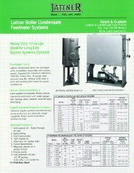
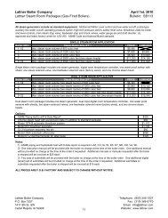
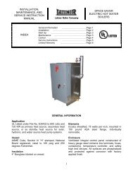
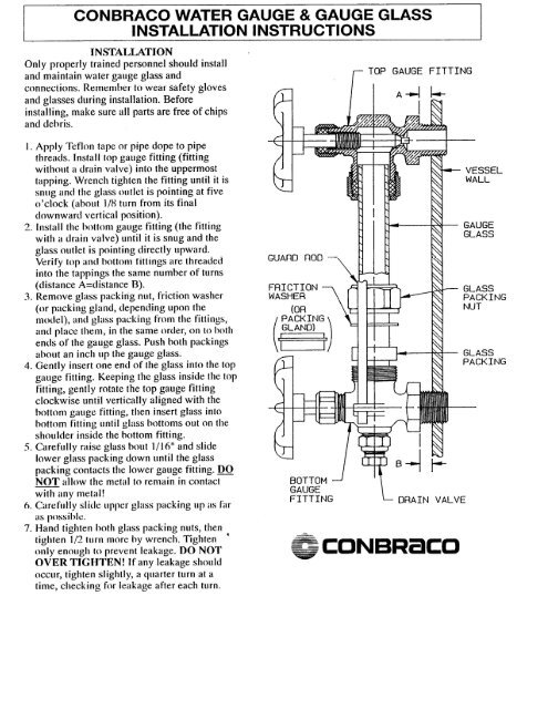
KUNKLE PRESSURE RELIEF VALVES<br />
Installation and Operating Instructions<br />
Pre-Installation Handling<br />
This pressure relief valve is designed to protect equipment from overpressure. The valve should be handled with care, not<br />
subjected to heavy shock loads, and protected to prevent contamination from getting inside. It should be installed correctly per<br />
A.S.M.E. <strong>Boiler</strong> & Pressure Vessel Code requirements. Failure to do so could result in property damage or serious injury to<br />
personnel. When hoisting the valve into position for installation, care should be exercised so that lifting straps do not contact<br />
the valve lift lever.<br />
Installation<br />
Always wear proper safety equipment, including safety glasses and ear protection.<br />
1. Mount the valve in a vertical position so that the valve body is self-draining. If a body drain port is provided, make sure it is<br />
open when required by the ASME code. Do not plug any bonnet vent openings. The inlet piping should be as short as<br />
possible, with no elbows, and equal to or greater than the size of the pressure relief valve inlet connection. This will help to<br />
limit the inlet pressure drop to 3% or less when the valve is relieving.<br />
2. When discharge piping is connected to valve outlet, make sure it is self draining if a body drain port is not used. The valve<br />
should not be connected to any discharge pipe that contains pressure before the valve opens or to any pipe where the<br />
pressure build-up is greater than 10% of the set pressure when the valve is open and relieving.<br />
Discharge piping, other than a short tailpipe, must be supported. For steam service, a drip pan elbow or flexible connection<br />
between the valve and the pipe should be used to prevent excessive pipe stress, due to thermal expansion, from being<br />
imposed on the valve body.<br />
3. For threaded valves, to prevent sealing compound from entering and damaging the valve, apply a small amount of pipe<br />
thread sealing compound to external threads only. Do not put any sealing compound on the first thread or on any internal<br />
threads. To do so may cause the sealing compound to enter the valve and cause seat leakage.<br />
Do not use the valve body or bonnet for installing the valve in threaded connections. Use the wrench flats provided to<br />
tighten the valve to the connecting pipe, and do not overtighten. To do so may cause valve leakage.<br />
4. For flanged valves, use new gaskets and tighten the mounting studs evenly.<br />
Operation<br />
1. Maintain a system operating pressure at least 5 psig or 10% below the set pressure of the valve, whichever is greater.<br />
Operating too close to the valve set pressure will cause seat leakage and will shorten the time between valve maintenance.<br />
2. Do not use the safety valve as a control valve to regulate system operating pressure. Excessive <strong>operation</strong> will cause the<br />
seat to leak and will require more frequent valve maintenance.<br />
3. ASME Section I and VIII valves equipped with lift levers are designed to be operated only when the system pressure is<br />
75% of set pressure or greater. ASME Section IV valves may be operated at any set pressure. When hand operating the<br />
valve, hold it open long enough to purge any foreign matter from the seat area. If a cable or wire is attached to the lift lever<br />
for remote actuation, make sure the direction of pull is the same as it would be if the lever were pulled directly by hand.<br />
Maintenance<br />
Maintenance should be performed on a regular basis. An initial inspection interval of 12 months is recommended. Depending<br />
on the service conditions and the condition of the valve, the inspection interval may be decreased or increased. Use only<br />
Kunkle parts for repair. Depending on the local jurisdictional requirements where the valve is installed, repairs may have to be<br />
made by a repair facility holding a VR stamp.<br />
WARNING!<br />
Removal of the seal wires or any attempt to adjust, repair or modify this product by non-qualified or non-authorized persons<br />
voids the product guarantee and may cause serious damage to equipment, personal injury, and death. Kunkle Valve is not<br />
liable for any damage resulting from misuse or misapplication of its products.<br />
Kunkle Valve Division Rev B 01/14/2002<br />
Phone: 828-669-5515 953 Old US 70, Black Mountain, NC 28711 Fax: 828-669-4017
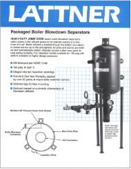
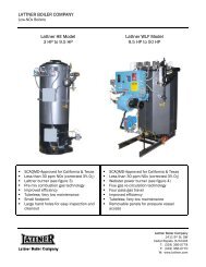
Series 150 and 157<br />
(Mercury Switch)<br />
Series 150S and 157S<br />
(Snap Switch, All Models except 157S-RB-P)<br />
Low Water Cut-Off/Pump Controllers<br />
For Steam <strong>Boiler</strong>s and Other Level Control Applications<br />
Typical Applications:<br />
– Primary or secondary pump controller/<br />
low water fuel cut-off<br />
for steam boilers<br />
– Motorized valve controller<br />
– Low water cut-off<br />
– High water cut-off<br />
– Alarm actuator<br />
• Before using this product read and understand instructions.<br />
• Save these instructions for future reference.<br />
• All work must be performed by qualified personnel trained in the proper application, installation,<br />
and maintenance of plumbing, steam, and electrical equipment and/or systems in<br />
accordance with all applicable codes and ordinances.<br />
• To prevent serious burns, the boiler must be cooled to 80˚F (27˚C) and the pressure must be<br />
0 psi (0 bar) before servicing.<br />
• To prevent electrical shock, turn off the electrical power before making electrical connections.<br />
• This low water cut-off must be installed in series with all other limit and operating controls<br />
installed on the boiler. After installation, check for proper <strong>operation</strong> of all of the limit and<br />
operating controls, before leaving the site.<br />
• We recommend that secondary (redundant) Low Water Cut-Off controls be installed on all<br />
steam boilers with heat input greater than 400,000 BTU/hour or operating above 15 psi of<br />
steam pressure. At least two controls should be connected in series with the burner control<br />
circuit to provide safety redundancy protection should the boiler experience a low water<br />
condition. Moreover, at each annual outage, the low water cut-offs should be dismantled,<br />
inspected, cleaned, and checked for proper calibration and performance.<br />
• • To prevent serious personal injury from steam blow down, connect a drain pipe to the control<br />
opening to avoid exposure to steam discharge.<br />
• To prevent a fire, do not use this low water cut-off to switch currents over 7.4A, 1/3 Hp at<br />
120 VAC or 3.7A, 1/3 Hp at 240 VAC, unless a starter or relay is used in conjunction with it.<br />
Failure to follow this warning could cause property damage, personal injury or death.<br />
WARNING<br />
CAUTION<br />
Installation & Maintenance<br />
Instructions MM-217(F)<br />
®<br />
! WARNING<br />
Series 150 and 150S<br />
Series 157 and 157S
OPERATION<br />
Maximum Pressure: 150 psi (10.5 kg/cm 2 )<br />
Electrical Ratings<br />
Enclosure rating: NEMA 1 General Purpose<br />
2<br />
PumpCircuit Rating (Amperes)<br />
Voltage Full Load Locked Rotor Pilot Duty<br />
120 VAC 7.4 44.4 345 VA at<br />
240 VAC 3.7 22.2 120 or 240 VAC<br />
Settings and Differential Pressures<br />
Values are ± 8” (3.2mm).<br />
Series 150, 150S, 157 and 157S<br />
Pressure<br />
0 psi<br />
(0 kg/<br />
cm 2)<br />
150 psi<br />
(10.5 kg/<br />
cm 2)<br />
PUMP<br />
OFF<br />
BURNER ON<br />
BURNER OFF<br />
Approximate<br />
Distance Above<br />
Cast Line Differential<br />
Setting In. (mm) In. (mm)<br />
Pump Off<br />
Pump On<br />
15 /16 (24)<br />
5 /8 (16)<br />
5/16 (8)<br />
Burner On<br />
Burner Off<br />
5 /8<br />
1 /4<br />
(16)<br />
(6.4)<br />
3/8 (16)<br />
Pump Off 13 Pump On<br />
/8<br />
5 /8<br />
(41)<br />
(16)<br />
3/4 (19)<br />
Burner On<br />
Burner Off<br />
7 /8<br />
0<br />
(22)<br />
(0)<br />
7/8 (22)<br />
150 psi (10.5 kg/cm 2 ) Levels 150 psi (10.5 kg/cm 2 ) Levels<br />
1 3/8"<br />
DIFFERENTIAL<br />
(35mm)<br />
BURNER<br />
OFF BURNER<br />
“CUT-OFF LEVEL”<br />
AT CAST LINE<br />
3/4"<br />
DIFFERENTIAL<br />
(19mm)<br />
PUMP OFF<br />
PUMP ON<br />
7/8"<br />
DIFFERENTIAL<br />
(22mm)<br />
NORMAL BOILER<br />
WATER LINE<br />
Alarm Circuit Rating<br />
Voltage Amps<br />
120 VAC 1<br />
240 VAC 1/2<br />
Model 150-MD, 150S-MD, 157-MD and 157S-MD<br />
Pressure<br />
0 psi<br />
(0 kg/<br />
cm 2)<br />
150 psi<br />
(10.5 kg/<br />
cm 2)<br />
1 13/16"<br />
DIFFERENTIAL<br />
(46mm)<br />
PUMP<br />
OFF<br />
BURNER<br />
OFF<br />
3 /4"<br />
DIFFERENTIAL<br />
(19mm)<br />
PUMP OFF<br />
PUMP ON<br />
Motor Horsepower<br />
Voltage Hp<br />
120 VAC 1/3<br />
240 VAC 1/3<br />
Approximate<br />
Distance Above<br />
Cast Line Differential<br />
Setting In. (mm) In. (mm)<br />
Pump Off<br />
Pump On<br />
15 /16 (24)<br />
9 /16 (14)<br />
3/8 (16)<br />
Burner Off 0 (0) N/A<br />
Pump Off 17 Pump On<br />
/16 (37)<br />
11/16 (17)<br />
3/4 (19)<br />
Burner Off - 3/8 (-16) N/A<br />
NORMAL BOILER<br />
WATER LINE<br />
BURNER CUT-OFF LEVEL<br />
3 /8 " (9.5mm) BELOW<br />
CAST LINE
Settings and Differential Pressures (continued)<br />
Values are ± 8” (3.2mm).<br />
Model 158/158S<br />
Pressure<br />
0 psi<br />
(0 kg/<br />
cm 2)<br />
150 psi<br />
(10.5 kg/<br />
cm 2)<br />
MOTORIZED<br />
VALVE<br />
CLOSED<br />
BURNER<br />
OFF<br />
BURNER ON<br />
BURNER OFF<br />
Approximate<br />
Distance Above<br />
Cast Line Differential<br />
Setting In. (mm) In. (mm)<br />
Motorized 15 /16 (24)<br />
Valve Closed<br />
Motorized<br />
Valve Open<br />
5 /8 (16)<br />
5/16 (8)<br />
Burner On<br />
Burner Off<br />
5 /8<br />
1 /4<br />
(16)<br />
(6.4)<br />
3/8 (16)<br />
Motorized 13 /8 (41)<br />
Valve Closed<br />
Motorized<br />
Valve Open<br />
5 /8 (16)<br />
3 /4 (19)<br />
Burner On<br />
Burner Off<br />
7 /8<br />
0<br />
(22)<br />
(0)<br />
7/8 (22)<br />
150 psi (10.5 kg/cm 2 ) Levels<br />
1 3 /8"<br />
DIFFERENTIAL<br />
(35mm)<br />
MOTORIZED<br />
VALVE<br />
CLOSED<br />
MOTORIZED<br />
VALVE<br />
OPEN<br />
3/4"<br />
DIFFERENTIAL<br />
(19mm)<br />
7/8"<br />
DIFFERENTIAL<br />
(22mm)<br />
NORMAL BOILER<br />
WATER LINE<br />
BURNER<br />
“CUT-OFF LEVEL”<br />
AT CAST LINE<br />
NOTE: Due to the slower <strong>operation</strong> of some<br />
motorized valves, complete valve opening<br />
or closing will occur at slightly different<br />
levels than indicated above.<br />
Model 158-MD/158S-MD<br />
Pressure<br />
0 psi<br />
(0 kg/<br />
cm 2)<br />
150 psi<br />
(10.5 kg/<br />
cm 2)<br />
1 13/16"<br />
DIFFERENTIAL<br />
(46mm)<br />
MOTORIZED<br />
VALVE<br />
CLOSED<br />
BURNER<br />
OFF<br />
Approximate<br />
Distance Above<br />
Cast Line Differential<br />
Setting In. (mm) In. (mm)<br />
Pump Off<br />
Pump On<br />
15 /16 (24)<br />
9 /16 (14)<br />
3/8 (16)<br />
Burner Off 0 (0) N/A<br />
Pump Off 17 /16 (37)<br />
3/4 (19)<br />
Pump On 11/16 (17)<br />
Burner Off - 3/8 (-16) N/A<br />
150 psi (10.5 kg/cm 2 ) Levels<br />
3 /4"<br />
DIFFERENTIAL<br />
MOTORIZED (19mm)<br />
VALVE<br />
OPEN<br />
CLOSED<br />
NORMAL BOILER<br />
WATER LINE<br />
BURNER CUT-OFF LEVEL<br />
3 /8 " (9.5mm) BELOW<br />
CAST LINE<br />
NOTE: Due to the slower <strong>operation</strong> of some<br />
motorized valves, complete valve opening<br />
or closing will occur at slightly different<br />
levels than indicated above.<br />
3
Settings and Differential Pressures (continued)<br />
Values are ± 8” (3.2mm).<br />
4<br />
Model 159/159S<br />
Pressure<br />
0 psi<br />
(0 kg/<br />
cm 2)<br />
150 psi<br />
(10.5 kg/<br />
cm 2)<br />
150 psi (10.5 kg/cm 2 ) Levels<br />
PUMP #1<br />
OFF<br />
PUMP #2<br />
ON<br />
1 3/8"<br />
DIFFERENTIAL<br />
(35mm)<br />
3/4"<br />
DIFFERENTIAL<br />
(19mm)<br />
PUMP #1<br />
OFF<br />
PUMP #1<br />
ON<br />
PUMP #2<br />
OFF<br />
PUMP #2<br />
ON<br />
Approximate<br />
Distance Above<br />
Cast Line Differential<br />
Setting In. (mm) In. (mm)<br />
Pump #1 Off<br />
Pump #1 On<br />
15 /16 (24)<br />
5 /8 (16)<br />
5/16 (8)<br />
Pump #2 Off<br />
Pump #2 On<br />
5 /8<br />
1 /4<br />
(16)<br />
(6.4)<br />
3/8 (16)<br />
Pump #1 Off 13 Pump #1 On<br />
/8<br />
5 /8<br />
(41)<br />
(16)<br />
3/4 (19)<br />
Pump #2 Off<br />
Pump #2 On<br />
7 /8<br />
0<br />
(22)<br />
(0)<br />
7/8 (22)<br />
7/8"<br />
DIFFERENTIAL<br />
(22mm)<br />
NORMAL BOILER<br />
WATER LINE<br />
PUMP #2 ON<br />
AT CAST LINE<br />
NORMAL BOILER<br />
WATER LINE<br />
PUMP #2 ON<br />
AT CAST LINE
INSTALLATION<br />
TOOLS NEEDED:<br />
Two (2) pipe wrenches, one (1) flathead screw<br />
driver, and pipe sealing compound.<br />
STEP 1 - Determine the Elevation at Which the<br />
Low Water Cut-Off/Pump Controller Must be Installed<br />
If the control will be the primary low<br />
water fuel cut-off, size the steam (top)<br />
and water (bottom) equalizing pipe lengths<br />
so that the horizontal cast line on the body<br />
is 1a” (35mm) below the boiler’s normal<br />
water level, but not lower than the lowest,<br />
safe permissible water level, as<br />
determined by the boiler manufacturer.<br />
OR<br />
If the control will be the secondary low<br />
water fuel cut-off, size the steam (top) and<br />
water (bottom) equalizing pipe lengths so<br />
that the horizontal cast line on the body is<br />
at or above, the lowest, safe permissible<br />
water level, as determined by the<br />
boiler manufacturer.<br />
STEP 2 - Installing the Low Water Cut-Off<br />
a. Using a pipe wrench, unscrew the plastic<br />
float blocking plug (A) from the low water<br />
cut-off body (B).<br />
Series 150 and 150S<br />
(except Model 150-B and<br />
150S-B)<br />
B<br />
A<br />
LOWEST PERMISSIBLE<br />
WATER LEVEL<br />
BURNER OFF<br />
LOWEST PERMISSIBLE<br />
WATER LEVEL<br />
IMPORTANT: Follow the boiler manufacturer's<br />
instructions along with all applicable codes and<br />
ordinances for piping, blow down valve and water<br />
gauge glass requirements.<br />
13/8" (35mm)<br />
WATER<br />
EQUALIZING<br />
PIPE<br />
WATER<br />
EQUALIZING<br />
PIPE<br />
STEAM EQUALIZING PIPE<br />
AS A PRIMARY<br />
LOW WATER CUT-OFF/PUMP CONTROLLER<br />
VERTICAL EQUALIZING PIPE<br />
BLOW DOWN VALVE<br />
STEAM EQUALIZING PIPE<br />
NORMAL BOILER WATER LINE<br />
BURNER “CUT-OFF LEVEL” AT CAST LINE<br />
AS A SECONDARY<br />
LOW WATER CUT-OFF/PUMP CONTROLLER<br />
BURNER “CUT-OFF LEVEL” AT CAST LINE<br />
VERTICAL EQUALIZING PIPE<br />
BLOW DOWN VALVE<br />
Models 150-B and 150S-B Series 157 and 157S<br />
A<br />
B<br />
B<br />
A<br />
5
6<br />
b. For Models 150-B and 150S-B and Series<br />
157 and 157S (For all other models,<br />
proceed to Step 3).<br />
Screw the w” NPT steel plug (C) (provided)<br />
in tapping (A).<br />
! CAUTION<br />
The plug must be reinstalled before control is<br />
shipped installed on the boiler, and removed<br />
when boiler is installed after shipment.<br />
Failure to follow this caution may damage float<br />
and operating mechanism.<br />
c. Mount and pipe the low water cut-off (D) on<br />
a vertical equalizing pipe (E) at the required<br />
elevation level, as determined in Step 1.<br />
Install a full ported blow down valve (G)<br />
directly below the lower cross of the water<br />
equalizing pipe (F).<br />
Note: 1” NPT tappings are provided, with<br />
the exception of some 157 and 157S models<br />
which are 14” NPT.<br />
a. Install a water column (H) (not<br />
included with product) for all models<br />
except Series 157 and 157S<br />
(with integral water column).<br />
b. Install a water gauge glass (J).<br />
Note: Gauge glass and tri-cocks<br />
not included with product.<br />
Models 150-B and 150S-B<br />
Series 157 and 157S<br />
J<br />
C A<br />
STEP 3 - Installing a Water Gauge Glass (Required on all steam boilers)<br />
J<br />
F<br />
Series 157 and 157S<br />
A<br />
E<br />
D<br />
G<br />
C<br />
All Other Models<br />
H
STEP 4 - Electrical Wiring<br />
Switch Operation<br />
! WARNING<br />
• To prevent a fire, do not use this product to switch currents over 7.4A, 1/3 Hp at 120 VAC or 3.7A, 1/3 Hp at 240<br />
VAC, unless a starter or relay is used in conjunction with it.<br />
• To prevent electrical shock, turn off the electrical power before making electrical connections.<br />
• This low water cut-off must be installed in series with all other limit and operating controls installed on the<br />
boiler. After installation, check for proper <strong>operation</strong> of all of the limit and operating controls, before leaving<br />
the site.<br />
• Modification of the switch assembly before or after installation could cause damage to the boiler and/or<br />
boiler system.<br />
Failure to follow this warning could cause electrical shock, an explosion and/or a fire, which could result in<br />
property damage, personal injury or death.<br />
For all Models except 158/158S and 159/159S<br />
<strong>Boiler</strong> feed pump off,<br />
burner on, alarm off.<br />
For Models 158 and 158S<br />
<strong>Boiler</strong> feed pump on,<br />
burner on, alarm off.<br />
<strong>Boiler</strong> feed pump on,<br />
burner off, alarm on.<br />
1 2 4 5 6 1 2 4 5 6 1 2 4 5 6<br />
Motorized valve closed,<br />
burner on, alarm off.<br />
Motorized valve open,<br />
burner on, alarm off.<br />
Motorized valve open,<br />
burner off, alarm on.<br />
1 2 3 4 5 6 1 2 3 4 5 6 1 2 3 4 5 6<br />
For Models 159 and 159S<br />
Pump #1 off,<br />
pump #2 off.<br />
Pump #1 on,<br />
pump #2 off.<br />
Pump #1 on,<br />
pump #2 on.<br />
1 2 5 6 1 2 5 6 1 2 5 6<br />
a. Using a flathead screwdriver, remove the<br />
junction box cover (K).<br />
K<br />
7
8<br />
b. Following the appropriate wiring diagram, (refer<br />
to page 9) based on your application requirements,<br />
and using BX armored cable or Thinwall<br />
electrical metal tubing connector fittings, make<br />
electrical connections to the junction box (L).<br />
Snap Switches (Series 150S and 157S)<br />
L<br />
PUMP<br />
SWITCH<br />
PUMP<br />
CIRCUIT<br />
TERMINALS<br />
ALARM<br />
CIRCUIT<br />
TERMINALS<br />
LOW WATER<br />
CUT-OFF<br />
TERMINALS<br />
L<br />
PUMP<br />
SWITCH<br />
LOW WATER<br />
CUT-OFF AND<br />
ALARM SWITCH<br />
Automatic Reset<br />
(All models except 158S and 159S)<br />
PUMP<br />
CIRCUIT<br />
TERMINALS<br />
ALARM<br />
CIRCUIT<br />
TERMINALS<br />
L<br />
MOTORIZED<br />
VALVE<br />
SWITCH<br />
LOW WATER<br />
CUT-OFF<br />
TERMINALS<br />
MOTORIZED<br />
VALVE<br />
TERMINALS<br />
LOW WATER<br />
CUT-OFF AND<br />
ALARM SWITCH<br />
Manual Reset<br />
(All models except 158S)<br />
Mercury Switches (Series 150 and 157)<br />
L<br />
PUMP<br />
SWITCH<br />
PUMP<br />
CIRCUIT<br />
TERMINALS<br />
ALARM<br />
CIRCUIT<br />
TERMINALS<br />
LOW WATER<br />
CUT-OFF<br />
TERMINALS<br />
(All models except 158<br />
and 159)<br />
CUT-OFF<br />
AND ALARM<br />
SWITCH<br />
L<br />
ALARM<br />
CIRCUIT<br />
TERMINALS<br />
1 2 3 4 5 6<br />
LOW WATER<br />
CUT-OFF<br />
TERMINALS<br />
Automatic Reset<br />
Model 158S<br />
TO<br />
ELECTRIC<br />
VALVE<br />
L<br />
TO<br />
LOW WATER<br />
ALARM<br />
PUMP<br />
SWITCH<br />
1 2 3 4 5 6<br />
LOW WATER<br />
CUT-OFF AND<br />
ALARM SWITCH<br />
PUMP<br />
CIRCUIT<br />
TERMINALS<br />
TO<br />
LOW WATER<br />
CUT-OFF<br />
ALARM<br />
CIRCUIT<br />
TERMINALS<br />
IMPORTANT: There must be<br />
a minimum space of 1/2”<br />
(13mm) between connector<br />
fittings and electrical live<br />
metal parts.<br />
L<br />
PUMP #1<br />
SWITCH<br />
LOW WATER<br />
CUT-OFF<br />
TERMINALS<br />
Manual Reset<br />
Model 158S-M<br />
L<br />
PUMP #1<br />
CIRCUIT<br />
TERMINALS<br />
LOW WATER<br />
CUT-OFF AND<br />
ALARM SWITCH<br />
PUMP #2<br />
CIRCUIT<br />
TERMINALS<br />
Automatic Reset<br />
Model 159S<br />
NO. 1 PUMP<br />
CIRCUIT<br />
NO. 2 PUMP<br />
CIRCUIT<br />
1 2 5 6<br />
Model 158 Model 159<br />
PUMP #2<br />
SWITCH
WIRING DIAGRAMS<br />
For Motorized Valves, refer to the valve manufacturer's wiring instructions.<br />
Low Water Cut-Off Only<br />
1. Main Line Switch - For burner circuits within the<br />
switch’s electrical rating.<br />
Pump Control Only<br />
1. Main Line Switch - For pump motors within the<br />
switch’s electrical rating.<br />
Note: For Models 159 and 159S, use terminals<br />
5 and 6 for pump #2.<br />
Alarm Circuit Only<br />
1. Main Line Switch - For burner circuits within<br />
the switch’s electrical rating.<br />
SEE PUMP<br />
CONTROL<br />
CIRCUIT<br />
12 456<br />
LINE LOAD<br />
12 456<br />
LINE LOAD<br />
12 456<br />
ALARM<br />
12 456<br />
NEUTRAL<br />
ALARM<br />
HOT<br />
HOT<br />
TO NEUTRAL<br />
TO BURNER CONTROL CIRCUIT<br />
2. Pilot Switch - To holding coil of a starter when<br />
the pump circuit exceeds the switch’s electrical<br />
rating.<br />
NEUTRAL<br />
HOT<br />
12 456<br />
ALARM<br />
2. Pilot Switch - To holding coil of a starter when<br />
the burner circuit exceeds the switch’s electrical<br />
rating.<br />
SEE PUMP<br />
CONTROL<br />
CIRCUIT<br />
12 456<br />
12 456<br />
12 456<br />
1. Low Water Alarm 2. High Water Alarm<br />
OR<br />
OR<br />
OR<br />
Combination Pump Control, Low Water Cut-Off and Alarm<br />
OR<br />
2. Pilot Switch - To holding coil of a starter when<br />
the burner circuit exceeds the switch’s electrical<br />
rating.<br />
ALARM<br />
LINE<br />
LOAD<br />
LINE<br />
LOAD<br />
LINE (3 PHASE)<br />
LOAD<br />
9
6. Re-attach the junction box cover (K).<br />
STEP 5 - Testing<br />
This control is factory calibrated for specific applications. The following testing procedure is only meant to<br />
serve as a verification of proper operating sequence.<br />
Dimensions provided are typical for a boiler not being fired and/or not at pressure. Actual operating<br />
ranges are shown on page 2 in the "Operation" section.<br />
IMPORTANT: Follow the boiler manufacturer’s start-up and operating instructions along with all applicable<br />
codes and ordinances. Note: Water levels stated below are only for 150 psi (10.5 kg/cm 2 ) <strong>operation</strong>.<br />
10<br />
Note:<br />
Cover must be installed correctly as shown<br />
a. Turn on the electric power to the boiler. With the<br />
boiler empty the pump should go on and the burner<br />
must remain off.<br />
! WARNING<br />
If the burner comes on, immediately turn the boiler off and make the<br />
necessary corrections.<br />
Failure to follow this warning could cause an explosion or fire and<br />
result in property damage, personal injury or death.<br />
b. The boiler should begin to fill with water.<br />
Watch the gauge glass (J) until the water<br />
level reaches approximately d” (22mm)<br />
above the horizontal cast line (M) on the low<br />
water cut-off.<br />
IMPORTANT: If water does not start filling the<br />
boiler, immediately turn off the the boiler and<br />
make the necessary corrections.<br />
J<br />
7 /8"<br />
(22mm)<br />
K<br />
ON<br />
OFF<br />
M
c. For automatic reset models only. When the water<br />
level reaches approximately d” (22mm) above the<br />
horizontal cast line (lower for MD models) the burner<br />
should come on (pump #2 should shut off with<br />
Models 159 and 159S).<br />
e.<br />
OR<br />
For manual reset models only. When the water<br />
level reaches approximately d” (22mm) above the<br />
horizontal cast line press the reset button (N). The<br />
burner should then come on.<br />
d. Continue watching the gauge glass (J) to<br />
see that the water continues to rise to<br />
approximately 1a” (35mm) (1 7 /16” (37mm)<br />
for MD models) above the horizontal cast<br />
line (M). The pump should shut off (the<br />
motorized valve should close with Models<br />
158 and 158S, or with Models 159 and<br />
159S, pump #1 should shut off).<br />
! CAUTION<br />
7 /8"<br />
(22mm)<br />
To prevent serious personal injury from steam pipe blow down, connect a pipe to avoid exposure to<br />
steam discharge.<br />
Failure to follow this caution could cause personal injury.<br />
Blow down the control when the water in the boiler<br />
is at its normal level and the burner is on. Follow<br />
Blow Down Procedure found in Maintenance<br />
Section on the last page of these instructions.<br />
INSTALLATION COMPLETE<br />
J<br />
N<br />
Snap Switch Models<br />
Mercury Switch Models<br />
N<br />
M<br />
11
MAINTENANCE<br />
SCHEDULE:<br />
• Blow down control as follows when boiler is<br />
in <strong>operation</strong>.<br />
– Daily if operating pressure is above 15 psi.<br />
– Weekly if operating pressure is below 15 psi.<br />
NOTE<br />
More frequent blow-down may be necessary due<br />
to dirty boiler water and/or local codes.<br />
• Disassemble and inspect annually. Replace<br />
the low water cut-off/pump controller if it is<br />
worn, corroded, or if components no longer<br />
operate properly.<br />
• Inspect the float chamber and equalizing piping<br />
annually. Remove all sediment and debris.<br />
• Replace head mechanism every 5 years.<br />
More frequent replacement may be required when<br />
severe conditions exist such as rapid switch cycling,<br />
surging water levels, and use of water treatment<br />
chemicals.<br />
• We recommend head mechanism replacement<br />
when the switch(es) no longer operate properly.<br />
If you choose to replace the switch(es), order the<br />
proper McDonnell & Miller replacement switch or<br />
switch assembly and follow the Repair Procedure<br />
provided.<br />
Replacement<br />
Switch Assembly<br />
! CAUTION<br />
2-Wire<br />
Pump<br />
Snap switches must be replaced as an<br />
assembly.<br />
3-Wire<br />
Burner<br />
Replacement<br />
Mercury Tubes<br />
BLOW DOWN PROCEDURE:<br />
! CAUTION<br />
To prevent serious personal injury from steam<br />
pipe blow down, connect a drain pipe to the<br />
control opening to avoid exposure to steam<br />
discharge.<br />
Failure to follow this caution could cause<br />
personal injury.<br />
Blow down the control when the water in the boiler<br />
is at its normal level and the burner is on. Slowly<br />
open the upper then the lower blow-down valves<br />
and observe the water level fall in the sight glass.<br />
Close the valves (lower first then upper) after<br />
verifying that the pump contacts have closed and<br />
the burner shuts off. If this does not happen,<br />
immediately shut off the boiler, correct the problem<br />
and retest.<br />
For Models 158 and 158S, close the blow down<br />
valve after the motorized valve opens and the<br />
burner shuts off. For Models 159 and 159S, close<br />
the blow down valve after both pumps come on. If<br />
this does not happen, immediately shut off the<br />
boiler and correct the problem.<br />
Valve #1<br />
Valve #2<br />
3500 N. Spaulding Avenue<br />
Chicago, Illinois 60618<br />
tel: 773 267-1600<br />
fax: 773 267-0991<br />
www.mcdonnellmiller.com<br />
©2003 ITT Industries Inc.<br />
Printed in U.S.A. 10-03 210341
This bulletin should be used by experienced personnel as a guide to the installation of series 26M controls. Selection<br />
or installation of equipment should always be accompanied by competent technical assistance. We encourage you to<br />
contact Gems Sensors or its local representative if further information is required.<br />
Specifications<br />
Control Design: Solid State components enclosed in clear lexan<br />
plug-in style housing. Housing carries no NEMA ratings.<br />
Contact Design: SPDT (1 form C): One normally open (N.O.)<br />
and one normally closed (N.C.) powered contacts.<br />
Contact Ratings: 10 A @ 120,240 VAC resistive (120°F), 1A @<br />
120, 240 VAC resistive (150°F), 1/3 H.P. @ 120, 240 VAC (120°F)<br />
Contact Life: Mechanical- 5 million <strong>operation</strong>s Electrical-<br />
100,000 <strong>operation</strong>s minimum at rated load.<br />
Supply Voltage: 120, 240 or 24 VAC models: +10% -15% 50/<br />
60 Hz. 208/240 model: 187 Vmin to 255 Vmax. VAC 50/60Hz<br />
Supply Current: Relay energized at 4.4 VA<br />
Secondary Circuit: 12 VAC RMS Voltage on probes. 1.5<br />
milli-amp Current.<br />
Sensitivity: Models operate from 4.7K to 100K maximum<br />
specific resistance.<br />
Temperature: -40 TO 150°F ambient<br />
Terminals: All connections #6-32 screw type terminals with pressure<br />
clamps.<br />
Time Delays: Standard – LLCO probe, 3 seconds standard for<br />
lowering level.<br />
Listings: U.L. limit control recognition (353). 240 and 208 volt<br />
units are not U.L. limit control recognized.<br />
3-1/2”<br />
2-3/4”<br />
5/8”<br />
Warrick ® Series 26M Controls<br />
Installation and Operation Bulletin<br />
2-3/8”<br />
Dimensional Diagram<br />
2.0”<br />
Installation<br />
1. Install octal socket in appropriate enclosure<br />
using two #6 or #8 metal screws.<br />
1A. Install rail mount socket on appropriate<br />
rail (DIN mount) in appropriate enclosure if<br />
applicable.<br />
2. Wire control per wiring diagram, following<br />
N.E.C. and local codes<br />
3. Install control module in socket.<br />
1-11/16”<br />
Sensitivities vs Maximum<br />
Probe Wire Distance*<br />
SENSITIVITY<br />
CHARACTER<br />
A<br />
B<br />
C<br />
D<br />
E<br />
* Based on type MTW or THHN<br />
wire, #14 or #16 Awg<br />
1-5/32”<br />
SENSITIVITY<br />
(KOHMS)<br />
2-5/16”<br />
4.7<br />
10<br />
26<br />
50<br />
100<br />
11/64”<br />
Dia.<br />
Form 261<br />
Sheet P/N 100204-1<br />
Rev. H<br />
DISTANCE<br />
(FT)<br />
900<br />
600<br />
250<br />
100<br />
50
L2<br />
AC Power<br />
L1<br />
3<br />
2<br />
4<br />
5<br />
1<br />
6<br />
11<br />
8<br />
7<br />
NC<br />
9<br />
10<br />
NO<br />
G LWCO<br />
Low Level Cut-0ff Probe<br />
Reference Probe<br />
Wiring Diagram<br />
Reset<br />
IF METALLIC, TANK MAY BE USED<br />
INSTEAD OF REFERENCE PROBE<br />
Options:<br />
Automatic Reset: (Reset terminals not<br />
used): When the liquid rises to the electrode<br />
on terminal 6, the control energizes, changing<br />
state of the load contacts. (LED will be<br />
lit) The control remains energized until the<br />
liquid level recedes below electrode on terminal<br />
6. The control then de-energizes, (LED<br />
will not be lit) returning load contacts to original<br />
state. Unless otherwise specified, there<br />
is a three second time delay on decreasing<br />
level. Liquid must be below probe on terminal<br />
6 for a full three seconds before control<br />
de-energizes.<br />
Manual Reset : (Normally closed<br />
pushbutton installed across terminals #7<br />
and #8): When the liquid rises to the electrode<br />
on terminal 6, the control will remain<br />
de-energized until the pushbutton is depressed.<br />
The control will then energize, (LED<br />
will be lit) changing the state of the contacts.<br />
The control remains energized until<br />
the liquid level recedes below electrode on terminal 6. The control then de-energizes, (LED will not be lit) returning load<br />
contacts to their original state. Unless otherwise specified, there is a three second time delay on decreasing level. Liquid<br />
must be below probe on terminal 6 for full three seconds before control de-energizes.<br />
Manual Reset with Optional Power Outage Feature: (Normally closed pushbutton across reset terminals) Control<br />
will ignore power loss to control. With liquid above electrode on terminal 6, a power outage will cause the control to<br />
de-energize, but will automatically energize upon return of power. However, loss of liquid will cause control to de-energize<br />
and remain so until liquid again rises to electrode and pushbutton is depressed.<br />
Dirty Electrode Detection: The LED will flash every half-second once the probe resistance reaches a value greater<br />
than the nominal control sensitivity rating. The relay state will not change until it exceeds the nominal sensitivity by more<br />
than 25% (typically) at nominal input voltage. At which time the LED and relay contact return to the dry state. Such a<br />
condition may suggest electrode maintance is required.<br />
Test Feature Allows LLCO circuit to be tested. Holding down the reset button for 3 seconds will allow the LLCO circuit<br />
to trip which simulates the loss of water, without the need of draining the water level in the boiler. The control will return to<br />
normal <strong>operation</strong> once the reset button is pressed a second time.<br />
26M X X X X X XX XX X<br />
Dirty Probe: Blank = No Dirty Probe, A = With Dirty Probe<br />
Time Delay Increasing Level: 00-90 seconds. Blank = 0 seconds<br />
Time Delay Decreasing Level: 03-90 seconds. Blank = 3 seconds<br />
Optional Character: Optional character chart<br />
Enclosure: 0=None, 1=NEMA 1, 4=NEMA 4<br />
Socket Style: A=11 Pin Octal, B=DIN mount, M=None,module only<br />
Supply Voltage: 1=120VAC, 2=240VAC, 3=24VAC, 8=208/240VAC<br />
Sensitivity : A=4.7K, B=10K, C=26K, D=50K, E=100K<br />
Gems Sensors Inc.<br />
One Cowles Road<br />
Plainville, CT 06062-1198<br />
Tel: 860-793-4579<br />
Fax: 860-793-4580<br />
A<br />
B<br />
C<br />
E<br />
F<br />
Y<br />
Z<br />
X<br />
Optional Character Chart<br />
N.C.<br />
Pushbutton<br />
X<br />
X<br />
X<br />
X<br />
No Option<br />
Power<br />
Outage<br />
X<br />
X<br />
X<br />
X<br />
Test<br />
Feature<br />
X<br />
X<br />
X<br />
X