
You also want an ePaper? Increase the reach of your titles
YUMPU automatically turns print PDFs into web optimized ePapers that Google loves.
Section I: Installation<br />
WARNING: All installation procedures must be followed completely by a competent installer familiar with boilers<br />
and boiler accessories.<br />
CAUTION: Read and follow all instructions before installing any boiler equipment. All cover plates, enclosures<br />
and guards must be maintained and in place at all times, except during maintenance and servicing.<br />
A. Unloading<br />
The boiler was loaded by <strong>Lattner</strong> (including any accessories)<br />
and accepted by the transport company as undamaged.<br />
Therefore, before unloading the equipment, determine<br />
whether any shipping damage is apparent. Once the<br />
equipment is lifted from the trailer, any damage sustained<br />
during transit and not filed with the transport company will be<br />
the responsibility of the rigger or purchaser.<br />
1. Lifting<br />
The boiler will arrive secured to a wooden skid/pallet and<br />
will include a lifting lug (top of the boiler). When moving<br />
or lifting the unit, DO NOT attach slings around the boiler<br />
or to the burner in an attempt to pull the boiler.<br />
2. Forklift<br />
If lifting with a forklift, extended forks should be used and<br />
placed beneath the skid. Care must be taken to ensure<br />
that the boiler sits correctly on the forks such that the unit<br />
does not topple. Always note the weight of the boiler<br />
relative to the lifting capacity of the forklift.<br />
3. Crane or Boom<br />
When lifting with a crane or boom, attach the hook to the<br />
lifting lug on top of the boiler. DO NOT attach slings or<br />
chains to any part of the boiler, boiler piping, or burner.<br />
B. Rigging<br />
Always use a competent rigger that has experience moving<br />
and setting boilers. If the unit will be moved into the<br />
permanent location with a forklift, crane, or boom follow the<br />
directions in section A. However, if moving the unit through a<br />
tight space or into an area that will not permit a forklift, etc.,<br />
place the boiler on rollers or on 2” pipes and roll the boiler<br />
into place. If the unit is dragged, attach chains to the base<br />
frame only.<br />
CAUTION: DO NOT lay the boiler on its side as the panels<br />
will not support the weight of the boiler without sustaining<br />
damage. If the entry is too narrow for the boiler and controls<br />
to pass through, removal of the trim and controls can be<br />
executed. One should properly denote all wiring and piping<br />
connections and match mark accordingly for attachment after<br />
the boiler is placed. It may be helpful to use a digital camera<br />
to record the location of trim items for reference.<br />
8<br />
C. Placement of <strong>Boiler</strong><br />
1. Floor<br />
<strong>Boiler</strong> must be placed on a level, noncombustible<br />
surface. NEVER install boiler on a wood floor or any<br />
other combustible surface (i.e., carpet, linoleum).<br />
2. Combustible Surface<br />
Underwriter’s Laboratories specifies the following<br />
minimum clearances to combustible surfaces:<br />
Top – 48”<br />
Sides – 36”<br />
Flue Pipe – 36”<br />
3. Non-Combustible Surface<br />
When placing boiler near non-combustible surfaces<br />
(i.e., cement or cinder block walls), maintain 18” around<br />
the boiler for servicing. NOTE: Any state or local fire<br />
and building codes requiring additional clearances take<br />
precedence over the above requirements.<br />
D. Combustion Air<br />
1. Ventilation<br />
The boiler room must be adequately ventilated to supply<br />
combustion air to the boiler. The vent must be opened<br />
to the outside to allow air to flow into the room. Proper<br />
sizing of the vent is important to ensure that sufficient<br />
free air is available for complete combustion and proper<br />
venting of the flue gases.<br />
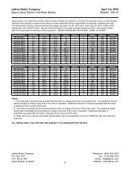
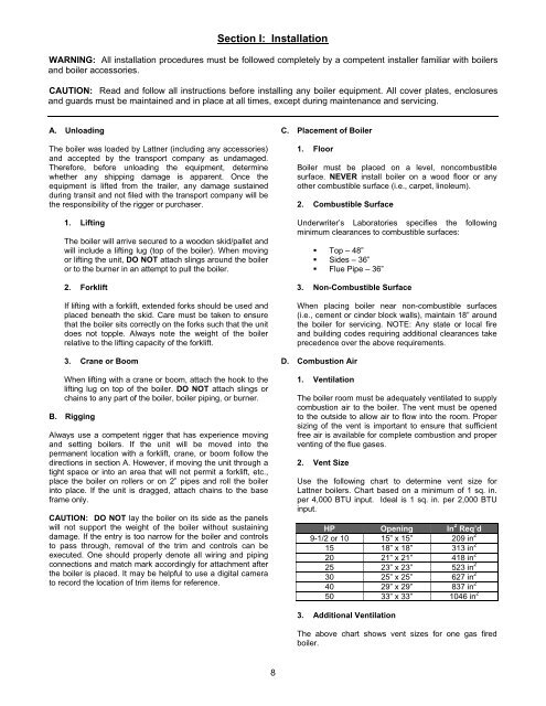
2. Vent Size<br />
Use the following chart to determine vent size for<br />
<strong>Lattner</strong> boilers. Chart based on a minimum of 1 sq. in.<br />
per 4,000 BTU input. Ideal is 1 sq. in. per 2,000 BTU<br />
input.<br />
HP Opening In 2 Req’d<br />
9-1/2 or 10 15” x 15” 209 in 2<br />
15 18” x 18” 313 in 2<br />
20 21” x 21” 418 in 2<br />
25 23” x 23” 523 in 2<br />
30 25” x 25” 627 in 2<br />
40 29” x 29” 837 in 2<br />
50 33” x 33” 1046 in 2<br />
3. Additional Ventilation<br />
The above chart shows vent sizes for one gas fired<br />
boiler.