Create successful ePaper yourself
Turn your PDF publications into a flip-book with our unique Google optimized e-Paper software.
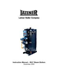
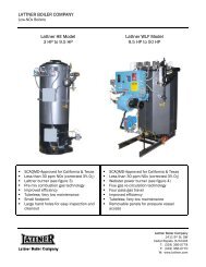
Instruction Manual – <strong>WLF</strong> Steam <strong>Boiler</strong>s<br />
2006 to 2007
General Description<br />
A. <strong>Boiler</strong> Design<br />
B. <strong>Boiler</strong> Connections<br />
C. <strong>Boiler</strong> Trim<br />
D. Fuel Burning System<br />
E. Fuel Train<br />
F. Control Panel<br />
G. Combustion Safeguard<br />
H. Guarantees<br />
I. Factory Tests<br />
J. Nameplates & Stamping<br />
Section I: Installation<br />
A. Unloading<br />
B. Rigging<br />
C. Placement of <strong>Boiler</strong><br />
D. Combustion Air<br />
E. Stack<br />
F. <strong>Boiler</strong> Shipped with Controls<br />
Removed<br />
G. Steam Outlet<br />
H. Blowdown Piping<br />
I. Safety Valve<br />
J. Gas Train Piping<br />
K. <strong>Boiler</strong> Feed Systems<br />
L. Electrical Connections<br />
M. Before Firing The <strong>Boiler</strong><br />
N. Pressuretrols: Controller & Limit<br />
O. Start Up of Standard Burners<br />
Section II: <strong>Boiler</strong> Care<br />
A. General<br />
B. New <strong>Boiler</strong> Clean Out<br />
C. Water Conditions<br />
D. Water Treatments & Chemicals<br />
E. Water Softener<br />
F. Foaming, Bouncing, & Chemicals<br />
G. Water Treatment Summary<br />
H. Blowdown<br />
I. Feedwater System<br />
J. Burner Adjustment<br />
K. Sight Glass<br />
L. External Inspections<br />
M. Internal Inspections<br />
Section III: Maintenance<br />
A. Daily Blowdown<br />
B. Weekly Maintenance<br />
C. General Maintenance<br />
D. Table 1: Recommended Testing<br />
Schedule<br />
E. Hand Hole Plate Removal & Re-<br />
Index<br />
…………………………………………………………………………….Page 4<br />
……………………………………………………………………………………4<br />
……………………………………………………………………………………4<br />
……………………………………………………………………………………5<br />
……………………………………………………………………………………5<br />
……………………………………………………………………………………6<br />
……………………………………………………………………………………6<br />
……………………………………………………………………………………6<br />
……………………………………………………………………………………6<br />
……………………………………………………………………………………7<br />
……………………………………………………………………………………7<br />
…………………………………………………………………………….Page 8<br />
……………………………………………………………………………………8<br />
……………………………………………………………………………………8<br />
……………………………………………………………………………………8<br />
……………………………………………………………………………………8<br />
……………………………………………………………………………………9<br />
……………………………………………………………………………………9<br />
……………………………………………………………………………………9<br />
……………………………………………………………………………………9<br />
………………………………………………………………………………….10<br />
………………………………………………………………………………….10<br />
………………………………………………………………………………….11<br />
………………………………………………………………………………….12<br />
………………………………………………………………………………….12<br />
………………………………………………………………………………….12<br />
………………………………………………………………………………….13<br />
…………………………………………………………………………..Page 15<br />
………………………………………………………………………………….15<br />
………………………………………………………………………………….15<br />
………………………………………………………………………………….15<br />
………………………………………………………………………………….15<br />
………………………………………………………………………………….15<br />
………………………………………………………………………………….15<br />
………………………………………………………………………………….16<br />
………………………………………………………………………………….16<br />
………………………………………………………………………………….16<br />
………………………………………………………………………………….16<br />
………………………………………………………………………………….17<br />
………………………………………………………………………………….17<br />
………………………………………………………………………………….18<br />
…………………………………………………………………………..Page 19<br />
………………………………………………………………………………….19<br />
………………………………………………………………………………….19<br />
………………………………………………………………………………….19<br />
………………………………………………………………………………….20<br />
………………………………………………………………………………….21<br />
2
Installation<br />
F. Sight Glass Removal & Re-<br />
Installation<br />
G. McDonnell Miller Servicing<br />
H. Cleaning Interconnecting Pipe<br />
I. Warrick Relay Replacement<br />
J. Auxiliary Low Water Cut-Off<br />
Probe Cleaning<br />
Section IV: Troubleshooting<br />
A. Normal Operation<br />
B. Basic Service Tools<br />
C. Before You Begin<br />
<strong>Lattner</strong> <strong>Boiler</strong> Limited Warranty<br />
Standard Terms & Conditions<br />
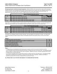
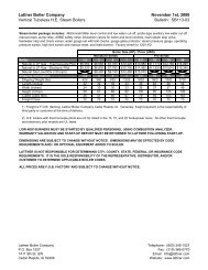
Product Support Literature<br />
………………………………………………………………………………….22<br />
………………………………………………………………………………….23<br />
………………………………………………………………………………….23<br />
………………………………………………………………………………….24<br />
………………………………………………………………………………….24<br />
…………………………………………………………………………..Page 25<br />
………………………………………………………………………………….25<br />
………………………………………………………………………………….25<br />
………………………………………………………………………………….25<br />
…………………………………………………………………………..Page 28<br />
…………………………………………………………………………..Page 29<br />
.......................................................................................................Page 30<br />
3
General Description<br />
WARNING: All installation procedures must be followed completely by a competent installer familiar with boilers<br />
and boiler accessories.<br />
CAUTION: Read and follow all instructions before installing any boiler equipment. All cover plates, enclosures<br />
and guards must be maintained and in place at all times, except during maintenance and servicing.<br />
A. <strong>Boiler</strong> Design<br />
The <strong>Model</strong> <strong>WLF</strong> is a four pass carbon steel vertical boiler of<br />
the waterleg tubeless design that includes an integral furnace<br />
and extended conductive heat transfer surfaces. The furnace<br />
is completely submerged within the normal operating water<br />
level. In accordance with the latest edition of the ASME Code,<br />
the boiler is constructed for either low pressure steam or high<br />
pressure steam to 150 psi.<br />
1. Gas Flow<br />
Heat transfer design of the <strong>Model</strong> <strong>WLF</strong> boiler provides<br />
four pass flow to ensure maximum heated gas travel and<br />
heat transfer. Refractory lined steel exhaust ports are<br />
incorporated for heated gas flow direction from the<br />
furnace to the finned convection surfaces. Symmetrical<br />
finned design and layout provides equalized flow of heat<br />
into each convection section from the furnace and<br />
successive gas passes, ensuring high efficiency.<br />
2. Water Circulation<br />
Feedwater make-up and/or return enter the bottom of the<br />
vessel below the steaming surface. By directing the<br />
make-up into a non-steaming portion of the boiler, we<br />
eliminate the possibility of collapsing steam bubbles and<br />
thereby work in harmony with the natural water<br />
circulating pattern within the boiler.<br />
3. Tubeless<br />
<strong>Boiler</strong> tubes are eliminated with the use of extended<br />
finned heat transfer surfaces. These fins are seal welded<br />
to the pressure vessel to enhance heat absorption into<br />
the boiler water. Fouling, plugging, and replacement of<br />
tubes are eliminated with the use of extended finned<br />
surfaces.<br />
4. Furnace<br />
The combustion chamber or furnace is centrally located<br />
within the pressure vessel. It consists of a single<br />
cylindrical tube attached to the top of the pressure vessel<br />
with ASME Code required stay bolts. It is symmetrical in<br />
layout and completely water backed, assuring a balanced<br />
flow circulating pattern under all load conditions.<br />
5. Inner Casing<br />
A non-metallic gas barrier encases the heat transfer fins,<br />
to ensure proper gas travel from the combustion<br />
chamber into each heat transfer zone. This barrier is<br />
covered with a steel wrapper that is in turn covered with<br />
a minimum 1-1/4” ceramic blanket, minimizing heat loss<br />
4<br />
and ensuring high fuel to steam efficiency. Blanket<br />
density exceeds 8 pounds per cubic foot. The steel<br />
inner wrapper ensures that the combustion byproducts<br />
will not diffuse through the blanket insulation and into<br />
the boiler room.<br />
6. Outer Casing<br />
The removable outer casing is fabricated of four 16<br />
gauge octagonal steel panels. Each panel is painted by<br />
a powder coating process on the inner and outer<br />
surfaces, ensuring corrosion resistance and longevity.<br />
Air space between the insulation and outer casing as<br />
well as the extra thick inner insulation provides a jacket<br />
temperature near ambient conditions.<br />
7. Waterside Inspection<br />
A minimum of two hand hole inspection plates are<br />
provided in the pressure vessel near the bottom for<br />
visual inspection and cleaning of the waterside<br />
internals. One hand hole inspection plate is located on<br />
the top of the boiler for additional waterside inspection.<br />
8. Flame Observation Port<br />
For visual inspection of the pilot and main flame ignition,<br />
a sight port is provided in the burner housing.<br />
9. <strong>Boiler</strong> Lifting Lugs<br />
One lug for 10 to 20 horsepower and two lugs on larger<br />
units are provided to facilitate lifting and rigging the<br />
boiler into place. The lug(s) is located on the top<br />
centerline of the pressure vessel.<br />
10. <strong>Boiler</strong> Base Frame<br />
A structural steel welded base is provided upon which<br />
the boiler is placed. The minimum height of the<br />
structural base is 4 inches and the boiler is welded to<br />
the base at four points.<br />
B. <strong>Boiler</strong> Connections<br />
The following connections are factory installed in<br />
accordance with the ASME:<br />
1. Steam Connection<br />
The system supply connection is located on the top of<br />
the boiler and is threaded as standard. In some<br />
instances or for specific project requirements, the<br />
nozzle connection may be flanged.
2. <strong>Boiler</strong> Blowdown Valve/Drain<br />
A boiler blowdown valve is provided on the front right<br />
side of the pressure vessel to completely drain the boiler<br />
as required, and for periodic bottom blowdown.<br />
3. Feedwater Make-Up<br />
A valve is provided on the front centerline of the pressure<br />
vessel near the bottom for connection to the system<br />
make-up and/or condensate return.<br />
4. Exhaust Gas Vent<br />
The connection for the stack or breaching is located at<br />
the rear near the top of the boiler. This is a sleeve<br />
connection, with the opening in accordance with the<br />
nominal dimension and rating sheets.<br />
C. <strong>Boiler</strong> Trim<br />
The following are factory installed standard trim and<br />
control items. Trim items are provided in accordance with<br />
the ASME Code and the controls and are UL listed.<br />
1. Relief Valve<br />
In compliance with the ASME Code, a steam boiler<br />
pressure relief valve(s) is provided. Size and quantity are<br />
determined by the valve setting, valve capacity, and the<br />
ASME Code. These may be shipped loose to prevent<br />
possible damage during shipment.<br />
2. Water Column<br />
Factory mounted and piped complete with gauge glass,<br />
gauge glass drain valve, gauge glass isolation valves,<br />
column drain valve, and a minimum of 1” equalized<br />
piping and crosses for inspection and clean-out.<br />
3. Low Water Cut-Off<br />
To prevent burner operation whenever a low water<br />
condition occurs, an electronic probe-sensing device, or<br />
float operated control is furnished in the water column.<br />
This device is wired in series to the burner combustion<br />
safeguard control to prevent burner operation whenever<br />
a low water condition occurs.<br />
4. Pump Control<br />
When a probe sensing main level control is furnished,<br />
two stainless steel probes are furnished in the water<br />
column to provide pump ON/OFF operation for water<br />
make-up. These probes are wired to an electronic<br />
interlock relay for pump or water valve control.<br />
However, if the column is a float-actuated device, a<br />
snap acting single pole single throw switch activates a<br />
pump contactor for ON/OFF pump or solenoid valve<br />
operation.<br />
5<br />
5. Auxiliary Low Water Cut-Off<br />
An additional control, separate from the primary low<br />
water control is provided to prevent burner operation if a<br />
low-low water condition exists. This device is an internal<br />
probe control located on the top of the pressure vessel,<br />
and requires manual reset whenever a low-low water<br />
condition occurs.<br />
6. Steam Pressure Gauge<br />
A 3-1/2" dial pressure gauge is furnished as standard.<br />
The range of the gauge will be in accordance with the<br />
safety valve setting, based on 1.5 times the valve<br />
setting for high-pressure units, and two times the design<br />
pressure of low-pressure units.<br />
7. Steam Pressure Controls<br />
9-1/2 to 25 Horsepower<br />
Two controls are furnished; one for ON/OFF<br />
operation while the other is to prevent burner<br />
operation if excess steam pressure is sensed and<br />
requires a manual reset.<br />
30 to 50 Horsepower<br />
Three (3) controls are supplied as standard. One<br />
control provides for ON/OFF operation in response<br />
to system demand and one is provided as a safety<br />
lockout with a manual reset requirement. The third<br />
control is for burner positioning at either low fire or<br />
high fire relative to steam demand.<br />
8. Valves<br />
Standard valve piping package, 9-1/2 to 30 horsepower,<br />
consists of: one (1) main steam stop valve, one (1)<br />
feedwater stop valve, one (1) feedwater spring loaded<br />
check valve, one (1) quick open bottom blowdown<br />
valve, and one (1) slow open blowdown valve. Valves<br />
for larger sizes are not provided unless requested.<br />
D. Fuel Burning System<br />
The factory-assembled boiler is furnished with a UL<br />
approved fuel burning forced draft packaged system.<br />
The packaged system is mounted and wired integral<br />
with the front centerline of the boiler.<br />
1. Burner Type<br />
The forced draft burner is designed for Natural or LP<br />
gas only.<br />
2. Burner Operation<br />
The burner is designed to operate in an ON/OFF mode<br />
for sizes 9-1/2 to 25 horsepower and LOW/HIGH/OFF<br />
for boilers 30 to 50 horsepower. Modulating burners are<br />
optional.
3. Ignition/Pilot<br />
Gas-fired units are equipped with a spark ignited gas<br />
pilot assembly. The gas pilot assembly includes a pilot<br />
gas cock, gas pressure regulator, ignition transformer,<br />
and pilot solenoid valve.<br />
4. Forced Draft Fan<br />
An integral fan assembly direct connected to a NEMA fan<br />
motor supplies the required combustion air. As standard,<br />
the fan motor is an open drip proof, high efficiency type,<br />
operating at 3,450 RPM.<br />
5. Air Proving Switch<br />
An air pressure-sensing switch is mounted on the burner<br />
to prevent fan or burner operation if sufficient air is not<br />
available for proper combustion or pilot ignition.<br />
6. Fuel/Air Control<br />
The control of combustion air is managed with an integral<br />
inlet air damper operating as follows:<br />
9-1/2 to 25 Horsepower<br />
Mechanically fixed for the correct combustion air to<br />
fuel ratio for ON/OFF firing.<br />
30 to 50 Horsepower<br />
Mechanically linked with the fuel valve and air<br />
damper to provide fuel/air ratio at low fire and high<br />
fire.<br />
E. Fuel Train<br />
The burner is equipped with factory mounted fuel safety<br />
control and safety shutoff valves for either natural gas or<br />
LP gas. Each fuel piping assembly is equipped, as a<br />
minimum with the following:<br />
1. Gas Assembly<br />
<strong>Boiler</strong> base rail mounted, piped and wired gas piping<br />
assembly, consisting of main gas pressure regulator,<br />
safety shutoff valves, manual shutoff cocks, fuel<br />
input control valve, in accordance with the latest UL<br />
and CSD-1 requirements.<br />
F. Control Panel<br />
A NEMA 1A enclosed (powder coated finish) control<br />
panel is mounted integral to the burner or on an<br />
independent bracket mounted on the boiler. This panel<br />
contains as a minimum the following components:<br />
1. <strong>Boiler</strong> ON/OFF Switch<br />
Provided to interrupt control power to the 120 volt<br />
control circuit. Does not disconnect the main power<br />
source.<br />
6<br />
2. Pump ON/OFF Switch<br />
Provided to isolate the pump control circuit.<br />
3. Terminals<br />
Provided for the connection of the 120/1/60 volt supply<br />
and for external connections for field wiring.<br />
4. Relays<br />
Water level control relays as described above.<br />
5. Wiring/Controls<br />
All devices and wiring are in accordance with the latest<br />
UL/NFPA 70 requirements. Each device is UL listed or<br />
recognized and bears the UL label or stamp.<br />
6. Wiring/Controls<br />
As standard, flexible conduit is used and as deemed<br />
necessary or in accordance with specifications, thin wall<br />
or rigid and seal tight may be used.<br />
G. Combustion Safeguard<br />
1. Solid State Control<br />
This pre-programmed solid state control is mounted<br />
adjacent to the burner, and provides for the safe start<br />
sequencing of the burner from start-up, run, normal<br />
shutdown, and safety shutdown.<br />
2. UV Scanner<br />
A flame-sensing device of the UV scanning principle is<br />
furnished on all boilers. Status indicating lights are<br />
furnished on the front face of this control for visual<br />
indication of the burner/boiler operation.<br />
H. Guarantees<br />
1. Efficiency<br />
The boiler package is guaranteed to operate at a<br />
minimum of 80% or greater, fuel input to steam pounds<br />
per hour output efficiency.<br />
2. Warranty<br />
The complete package is warranted for a period of one<br />
(1) year from the date of initial start-up or 18 months<br />
from the date of shipment or notice to ship, whichever<br />
occurs first.<br />
3. Damage<br />
This guarantee does not include items that are<br />
damaged due to circumstances of carelessness,<br />
neglect, or operating the unit beyond its capacity and<br />
rating.
I. Factory Tests<br />
1. Pressure Vessel<br />
The boiler is subjected to an ASME certified hydrostatic<br />
pressure test to ensure the pressure vessel meets the<br />
standards of the ASME. In accordance with the ASME<br />
Code (Section IV Heating <strong>Boiler</strong>s or Section I Power<br />
<strong>Boiler</strong>s), this test is supervised by an independent<br />
inspection agency. Upon acceptance of the test by the<br />
authorized independent inspector, the unit is stamped<br />
with the "H" symbol for 15 psi design units and with the<br />
"S" symbol for 150 psi and greater designs. One copy of<br />
the ASME data sheets is provided to the purchaser.<br />
One copy is sent to the National Board of Pressure<br />
Vessel Inspectors. The original copy is archive at<br />
<strong>Lattner</strong>.<br />
2. <strong>Boiler</strong> Piping Hydro<br />
Each Section I High Pressure <strong>Boiler</strong> ("S" stamped), is<br />
subjected to an additional hydrostatic pressure test. This<br />
test includes the integral steam and water trim piping<br />
and the trim valves. An ASME P-6 piping hydro<br />
certificate can be provided for an additional cost.<br />
7<br />
3. Burner/Controls<br />
To ensure proper operation of the combustion<br />
safeguard control, ignition, and main fuel light off the<br />
burner manufacturer subjects the packaged burner to a<br />
preliminary factory fire test. All burner and boiler<br />
controls are checked for circuit continuity and operation<br />
after mounting and wiring the burner onto the boiler.<br />
J. Nameplates & Stamping<br />
1. National Board of Pressure Vessel Inspectors<br />
The National Board of Pressure Vessel Inspectors<br />
registration number is stamped on the pressure vessel<br />
along with the boiler serial number, year built, maximum<br />
boiler output and minimum safety valve capacity. This<br />
information is stamped on the top head of the pressure<br />
vessel. A facsimile nameplate of this data stamping is<br />
mounted near or on the front door of the boiler control<br />
panel.
Section I: Installation<br />
WARNING: All installation procedures must be followed completely by a competent installer familiar with boilers<br />
and boiler accessories.<br />
CAUTION: Read and follow all instructions before installing any boiler equipment. All cover plates, enclosures<br />
and guards must be maintained and in place at all times, except during maintenance and servicing.<br />
A. Unloading<br />
The boiler was loaded by <strong>Lattner</strong> (including any accessories)<br />
and accepted by the transport company as undamaged.<br />
Therefore, before unloading the equipment, determine<br />
whether any shipping damage is apparent. Once the<br />
equipment is lifted from the trailer, any damage sustained<br />
during transit and not filed with the transport company will be<br />
the responsibility of the rigger or purchaser.<br />
1. Lifting<br />
The boiler will arrive secured to a wooden skid/pallet and<br />
will include a lifting lug (top of the boiler). When moving<br />
or lifting the unit, DO NOT attach slings around the boiler<br />
or to the burner in an attempt to pull the boiler.<br />
2. Forklift<br />
If lifting with a forklift, extended forks should be used and<br />
placed beneath the skid. Care must be taken to ensure<br />
that the boiler sits correctly on the forks such that the unit<br />
does not topple. Always note the weight of the boiler<br />
relative to the lifting capacity of the forklift.<br />
3. Crane or Boom<br />
When lifting with a crane or boom, attach the hook to the<br />
lifting lug on top of the boiler. DO NOT attach slings or<br />
chains to any part of the boiler, boiler piping, or burner.<br />
B. Rigging<br />
Always use a competent rigger that has experience moving<br />
and setting boilers. If the unit will be moved into the<br />
permanent location with a forklift, crane, or boom follow the<br />
directions in section A. However, if moving the unit through a<br />
tight space or into an area that will not permit a forklift, etc.,<br />
place the boiler on rollers or on 2” pipes and roll the boiler<br />
into place. If the unit is dragged, attach chains to the base<br />
frame only.<br />
CAUTION: DO NOT lay the boiler on its side as the panels<br />
will not support the weight of the boiler without sustaining<br />
damage. If the entry is too narrow for the boiler and controls<br />
to pass through, removal of the trim and controls can be<br />
executed. One should properly denote all wiring and piping<br />
connections and match mark accordingly for attachment after<br />
the boiler is placed. It may be helpful to use a digital camera<br />
to record the location of trim items for reference.<br />
8<br />
C. Placement of <strong>Boiler</strong><br />
1. Floor<br />
<strong>Boiler</strong> must be placed on a level, noncombustible<br />
surface. NEVER install boiler on a wood floor or any<br />
other combustible surface (i.e., carpet, linoleum).<br />
2. Combustible Surface<br />
Underwriter’s Laboratories specifies the following<br />
minimum clearances to combustible surfaces:<br />
Top – 48”<br />
Sides – 36”<br />
Flue Pipe – 36”<br />
3. Non-Combustible Surface<br />
When placing boiler near non-combustible surfaces<br />
(i.e., cement or cinder block walls), maintain 18” around<br />
the boiler for servicing. NOTE: Any state or local fire<br />
and building codes requiring additional clearances take<br />
precedence over the above requirements.<br />
D. Combustion Air<br />
1. Ventilation<br />
The boiler room must be adequately ventilated to supply<br />
combustion air to the boiler. The vent must be opened<br />
to the outside to allow air to flow into the room. Proper<br />
sizing of the vent is important to ensure that sufficient<br />
free air is available for complete combustion and proper<br />
venting of the flue gases.<br />
2. Vent Size<br />
Use the following chart to determine vent size for<br />
<strong>Lattner</strong> boilers. Chart based on a minimum of 1 sq. in.<br />
per 4,000 BTU input. Ideal is 1 sq. in. per 2,000 BTU<br />
input.<br />
HP Opening In 2 Req’d<br />
9-1/2 or 10 15” x 15” 209 in 2<br />
15 18” x 18” 313 in 2<br />
20 21” x 21” 418 in 2<br />
25 23” x 23” 523 in 2<br />
30 25” x 25” 627 in 2<br />
40 29” x 29” 837 in 2<br />
50 33” x 33” 1046 in 2<br />
3. Additional Ventilation<br />
The above chart shows vent sizes for one gas fired<br />
boiler.
If there is other equipment in the room that uses air<br />
(large water heaters, air compressors, other boilers,<br />
exhaust fans, etc.), additional venting capacity is<br />
required.<br />
E. Stack<br />
1. Specifications<br />
Install all stacks in compliance with state and local<br />
codes. <strong>Lattner</strong> recommends double wall stack per ANSI<br />
Z2231.1, appliance category III for positive vent pressure<br />
systems for boilers operating with a maximum continuous<br />
temperature not exceeding 1000°F.<br />
2. Stack Size<br />
The entire stack must be the same size as the stack<br />
outlet on the boiler or one size larger. If the boiler stack is<br />
connected to other equipment, the stack size must be<br />
increased. NOTE: Any equipment with a forced draft<br />
burner must be vented separately from equipment with<br />
atmospheric burners. NEVER tie these stacks together.<br />
3. Connections<br />
Limit connections to one of the following combinations:<br />
Two 90 degree elbows,<br />
One 90 degree elbow and one tee,<br />
One 90 degree and two 45 degree elbows, or<br />
Four 45 degree elbows.<br />
4. Overall Length<br />
Avoid long runs of stack. A general rule is not to exceed<br />
15 feet for every inch of stack diameter. For example, if<br />
the stack is 6” in diameter then the overall stack should<br />
not exceed 90 feet in length and height combined.<br />
5. Horizontal Stack<br />
Avoid any horizontal runs of stack. If unavoidable,<br />
horizontal runs should have a minimum incline of 3” per<br />
foot. If a long horizontal run (4 feet or more) cannot be<br />
avoided, a draft inducer may be required to properly vent<br />
combustion gases.<br />
6. Draft Regulation<br />
A barometric draft regulator should be utilized if unusual<br />
drafts exist or stack is abnormally high (tall).<br />
7. Walls & Ceilings<br />
When passing through combustible walls or ceilings, a<br />
stack thimble is required. The thimble must be double<br />
wall stack, 6” larger in diameter than the vent stack. The<br />
material used to close the opening between the stack<br />
and the stack thimble must be non-combustible.<br />
F. <strong>Boiler</strong> Shipped with Controls Removed<br />
1. Reassemble<br />
See assembly print in this section, p. 15.<br />
9<br />
2. Wiring<br />
Re-wiring the controls will be covered in L: Electrical<br />
Connections. DO NOT connect the power supply at<br />
this time.<br />
G. Steam Outlet<br />
1. Pipe Size<br />
Size steam pipe according to system requirements.<br />
2. Outlet Size<br />
Refer to product literature sheet for steam outlet size on<br />
a particular boiler model.<br />
3. Steam Stop Valve<br />
Install a steam stop valve in the steam line as close to<br />
the boiler as is practical. This allows boiler to be<br />
isolated from the system during service work and may<br />
be helpful in throttling steam flow. Required by ASME<br />
Code if the boiler is operated over 15 psi. Valve shall<br />
be rising stem or gate type valve.<br />
4. Steam Piping<br />
Steam line should be pitched downward away from the<br />
boiler and toward a steam trap. If using a steam<br />
solenoid valve, the steam line should slope upward<br />
slightly to the solenoid valve, and after the solenoid<br />
valve, the steam line should slope downward.<br />
5. Code Standards<br />
Piping must comply with all industry standards (ex.<br />
ANSI B31.1) and all state and local codes.<br />
H. Blowdown Piping (See diagram below)<br />
1. <strong>Boiler</strong> Bottom Blowdown<br />
DO NOT REDUCE. Blowdown piping and all fittings<br />
must be the same size as the boiler blowdown<br />
connection (refer to product literature sheets).<br />
Low pressure boilers, operating at 15 psi or less,<br />
require one blowdown or drain valve. The pressure<br />
rating of the valve must be equal to or greater than the<br />
pressure of the boiler safety valve but not lower than 30<br />
psi.
<strong>Boiler</strong>s operating 16 psi to 100 psi inclusive require a ytype<br />
gate or a ball valve rated for 125 WSP.<br />
<strong>Boiler</strong>s operating 101 psi to 150 psi require piping<br />
designed for a pressure of 125% of the boiler safety<br />
valve set pressure (schedule 80 blowdown piping), one<br />
quick opening, and one slow opening blowdown valve. If<br />
cast iron, these valves must be class 250, or if steel,<br />
these valves must be class 150, or if bronze, a WSP<br />
rating of at least 200.<br />
Standard globe valves that form a pocket inside the valve<br />
are not acceptable blowdown valves. Y-type, gate, and<br />
ball valves are acceptable blowdown valves.<br />
Galvanized piping is not acceptable for boiler blowdown<br />
piping.<br />
2. Automatic Bottom Blowdown<br />
A <strong>Lattner</strong> automatic bottom blowdown valve may be used<br />
in place of one of the manual blowdown valves.<br />
3. Control/Water Column Blowdown<br />
A water column level control is supplied with drain valve.<br />
Connect the control line to the bottom blowdown line<br />
after the second bottom blowdown valve.<br />
4. Blowdown Discharge<br />
All boiler blowdown water must be discharged to a safe<br />
location, specifically to a blowdown separator.<br />
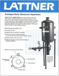
5. Blowdown Separator<br />
Select a <strong>Lattner</strong> blowdown separator according to the<br />
size of the boiler blowdown connection.<br />
Blowdown<br />
Separator<br />
Connection<br />
<strong>Model</strong><br />
1” 810<br />
1-1/2” 1450 or 1455<br />
2” 1600<br />
2-1/2” 1800<br />
6. Inspection Opening<br />
The extra coupling in the separator vessel is an<br />
inspection opening. The inspection opening will be<br />
plugged.<br />
7. Vent<br />
The blowdown separator must be vented to atmosphere.<br />
Vent pipe must discharge through the roof outside.<br />
DO NOT reduce the vent pipe size. NEVER connect the<br />
vent pipe from the condensate tank to the separator vent.<br />
8. Separator Drain<br />
The water leaving the separator through the drain should<br />
be piped to the sewer. Some codes require the water to<br />
pass through an air gap before entering the sewer.<br />
10<br />
9. Aftercooler<br />
If the water must be cooled before entering the sewer<br />
(required by some codes), then an aftercooler must be<br />
used. The aftercooler attaches to the separator drain<br />
connection and mixes cold water with the hot drain<br />
water. Units may be either manual or automatic. Select<br />
the aftercooler according to separator drain size.<br />
Separator Manual Automatic<br />
810 205M 205A<br />
1450,1455 301M 301A<br />
1600 525M 525A<br />
1800 625M 625A<br />
10. Cooling Water Supply<br />
Connect cold water supply pipe to aftercooler.<br />
11. Dead <strong>Boiler</strong> Drain Valve<br />
For draining the boiler when it is cool and not under<br />
pressure, the entire drain line must be lower than the<br />
bottom of the boiler. Pipe to sewer or floor drain. Valve<br />
must be rated up to the maximum allowable working<br />
pressure of the boiler.<br />
12. Codes & Standards<br />
All blowdown piping, drain and sewer connections,<br />
water piping and separator connections must be done in<br />
strict compliance with all applicable codes.<br />
I. Safety Valve<br />
1. Installation<br />
Be sure safety valve is threaded securely into the boiler<br />
or into the elbow supplied with boiler. The safety valve<br />
will always be installed in the upright position<br />
2. Discharge<br />
Pipe the safety valve outlet to a safe point of discharge.<br />
DO NOT reduce the safety valve discharge piping.<br />
NEVER plug the safety valve outlet.<br />
3. Supports<br />
Safety valve piping should be secured by clamps or<br />
braces to a wall or structural member. Do not allow the<br />
discharge piping to hang on the safety valve.<br />
4. Codes & Standards<br />
All safety valve piping and supports must conform to all<br />
applicable codes.<br />
J. Gas Train Piping<br />
1. Components<br />
In general, a gas train should include a manual gas<br />
cock, a main gas pressure regulator, a main gas valve,<br />
a safety shut-off gas valve, a pilot gas pressure<br />
regulator, a pilot gas valve, and a flame failure control.
2. Diaphragm Gas Valve<br />
This valve is the main gas valve. A separate gas<br />
pressure regulator must be used to regulate main burner<br />
pressure.<br />
3. Motorized Gas Valve<br />
With the motorized gas valve, the main gas valve and<br />
pressure regulator are two separate components. The<br />
motorized gas valve is a two-piece valve. The lower<br />
section is the valve body, which is a plunger valve. The<br />
upper section is the actuator. The actuator has a small<br />
built-in hydraulic system. The hydraulic system opens<br />
and closes the valve. The motorized gas valve is a gas<br />
valve only, and has no other functions. This gas train<br />
requires a separate main gas pressure regulator, pilot<br />
gas pressure regulator and pilot valve.<br />
The boiler will be supplied with a Honeywell flame<br />
safeguard control and an ignition transformer. With these<br />
controls, the boiler will have a spark-ignited pilot. This<br />
system will shut off the main and pilot gas within four<br />
seconds of a pilot failure.<br />
NOTE: For additional information on the gas train refer to<br />
the assembly prints and product literature sheets (power<br />
burner manual included).<br />
4. Gas Supply Pipe<br />
The gas pipe to the boiler must be at least the same size<br />
as the gas train supplied with the boiler. DO NOT<br />
reduce.<br />
5. Drip Leg<br />
Gas supply piping must be installed with a proper drip<br />
leg ahead of any gas train components.<br />
6. Gas Supply Pressure<br />
Natural Gas: Supply pressure should be between 6” to<br />
11” water column ahead of the gas pressure regulator.<br />
Minimum supply pressure when the boiler is operating<br />
should be 4-1/4” to 4-1/2” water column.<br />
Liquid Propane: Gas supply pressure is normally 11”<br />
water column.<br />
WARNING: NEVER use Teflon tape on any part of the<br />
gas train piping. This will void any warranty on the gas<br />
train assembly.<br />
7. Codes & Standards<br />
All gas piping must be done in accordance with all<br />
applicable codes (National Fuel Gas Code, utility<br />
company requirements, local building codes etc.).<br />
K. <strong>Boiler</strong> Feed Systems<br />
1. Condensate Return Systems<br />
11<br />
a. Make-Up Water Supply<br />
Connect city water line to the float valve provided<br />
with the boiler feed system.<br />
LV5 through LV35 use 1/2” NPT<br />
R1-Jr through R5 use 1/2” NPT<br />
LV60 though LV100 use 3/4” NPT<br />
R7 through R12 use 3/4” NPT<br />
Install a manual shut-off valve in the water line.<br />
b. Pump Suction Line<br />
This is pre-piped from the factory with an isolation<br />
valve and strainer.<br />
c. Pump Discharge Line<br />
DO NOT reduce. Use 1” NPT pipe and fittings<br />
between pump and boiler. Install two spring-loaded<br />
check valves. Install a hand shut-off valve between<br />
the last check valve and the boiler. Keep the<br />
number of elbows and fittings to a minimum.<br />
d. Condensate Return Vent<br />
Condensate return tank must be properly vented to<br />
atmosphere. Vent should discharge through the<br />
roof or through a wall to the outside. Do not reduce<br />
the vent pipe size.<br />
LV5 through LV35 use 1” NPT<br />
R1-Jr through R5 use 1” NPT<br />
LV60 though LV100 use 1-1/2” NPT<br />
R7 through R12 use 1-1/2” NPT<br />
e. Overflow<br />
Pipe to floor drain. Overflow connection should be<br />
at least as large as the condensate return.<br />
f. Drain Connection<br />
Pipe to floor drain. Install a valve in the line. 1” NPT<br />
line is sufficient.<br />
2. Solenoid Water Valve<br />
a. Water Pressure<br />
This system will work only if the water supply<br />
pressure is at least 10 psi higher than the boiler<br />
pressure.<br />
b. Water Inlet<br />
Refer to the boiler assembly print for correct<br />
connection and location of feedwater inlet.<br />
c. Piping<br />
The solenoid water valve assembly shall be piped<br />
in the following order: Y-type strainer, solenoid<br />
valve, spring loaded check valve, globe valve, and
oiler. All pipe is 1/2” NPT.<br />
d. Water Supply<br />
Connect water supply to the strainer.<br />
L. Electrical Connections<br />
CAUTION: All electrical work shall be done by a competent<br />
electrician. All wiring must be done in strict accordance with<br />
the National Electrical Code and any state or local codes.<br />
1. Reconnecting Controls<br />
If the boiler was shipped with controls removed, reconnect<br />
the wires according to the wiring diagram. All<br />
wires that need to be reconnected will have a tag<br />
indicating the control or terminals to which they must be<br />
connected.<br />
2. Electrical Supply<br />
Supply 120 volt single phase from a separate fused<br />
disconnect.<br />
Use a 15 amp circuit breaker or fused disconnect if the<br />
boiler has a solenoid water feed valve or a pump motor<br />
1/2 hp or less or a motor starter for a three phase pump.<br />
Use a 20 amp circuit breaker or fused disconnect if the<br />
boiler has a 3/4 hp pump motor, 120 volt single phase.<br />
3. Power Supply<br />
Connect the power supply to the terminals in the panel<br />
box as shown on the wiring diagram. "Hot" side will be<br />
marked L1. Neutral will be marked L2.<br />
4. Secure Connections<br />
After all wiring is complete and before any power is<br />
supplied to the boiler, be sure all wiring connections are<br />
tight.<br />
M. Before Firing The <strong>Boiler</strong><br />
1. Spare Fittings<br />
Check that all unused pipe nipples are plugged or<br />
capped.<br />
2. Float Block<br />
Remove the float block screwed into the body of the<br />
McDonnell Miller level control. Replace with a malleable<br />
iron plug (supplied with the boiler).<br />
3. Condensate Return System<br />
Make sure there is make-up water supply to the tank.<br />
Make sure there is water in the tank.<br />
4. Turn On<br />
Turn on the pump switch. Pump or solenoid valve should<br />
start immediately. If not, see troubleshooting section.<br />
12<br />
5. Check for Leaks<br />
While the boiler is filling, check for leaks in the piping<br />
and around boiler. If there are leaks, turn off the pump<br />
switch and fix all leaks before continuing.<br />
6. Solenoid Feedwater Valve<br />
If a solenoid water valve is used, make sure the water<br />
supply is connected.<br />
N. Pressuretrols: Controller & Limit<br />
1. Standard<br />
All <strong>Lattner</strong> steam boilers will have at least two pressure<br />
switches, a "controller" and a "limit”.<br />
2. Controller<br />
Before the boiler is started, the steam pressure is 0 psi.<br />
At this point, the controller is in the "ON" condition and<br />
is calling for heat. When the boiler switch is turned on,<br />
the boiler will fire and start generating steam. As the<br />
boiler fires, the steam pressure will rise. When the<br />
steam pressure reaches the controller's set point, the<br />
controller will shut off the burner. As steam is used, the<br />
pressure will begin to drop. When steam pressure drops<br />
enough, the controller will start the burner again. The<br />
controller will continue to operate in this manner to<br />
maintain boiler pressure.<br />
3. Setting The Controller (see diagram next page)<br />
On the left side of the pressuretrol is the set point<br />
indicating scale labeled "MAIN". Turn the main scale<br />
adjustment screw until the set point indicator aligns with<br />
the desired operating pressure. Turn screw clockwise to<br />
increase pressure, counterclockwise to decrease<br />
pressure.<br />
4. Differential<br />
When the boiler pressure reaches the main set point the<br />
controller shuts off the burner. The pressure must drop<br />
by a set amount before the controller will turn on the<br />
burner again. This amount is called the differential. The<br />
differential is adjustable.<br />
5. Setting The Differential (see diagram next page)<br />
On the far left side of the pressuretrols is the differential<br />
indicating scale labeled "DIFF". Turn the differential<br />
adjusting screw until the indicator aligns with the<br />
desired differential. A minimum differential will maintain<br />
the boiler pressure closer to the set point. A larger<br />
differential will help prevent rapid on and off cycling of<br />
the boiler.<br />
6. Limit<br />
The limit switch is similar in operation to the controller<br />
but has a slightly higher set point. If the controller fails<br />
to shut off the boiler and the steam pressure continues<br />
to rise, the limit switch will shut down the boiler. The<br />
controller is an operating switch; the limit serves as an
auxiliary safety cut-off. The limit switch is supplied with a<br />
manual reset function. If the steam pressure trips the<br />
high limit switch, the limit locks in the off position. The<br />
limit switch will not reset until the manual reset lever is<br />
pressed.<br />
7. Setting The Limit (see diagram below)<br />
This is done using the same procedure as for the<br />
controller. The limit setting will be slightly higher than the<br />
controller's set point.<br />
Low pressure boilers (less than 15 psi): Set the limit<br />
switch 4 psi higher than the controller and 3 psi lower<br />
than the safety valve setting.<br />
High pressure boilers (greater than 15 psi): Set the limit<br />
switch at least 10 psi higher than the controller and 5 psi<br />
lower than the safety valve setting.<br />
8. Night Operating Pressure Switch<br />
A third pressure switch may be supplied as an option.<br />
This switch allows the boiler to operate at low pressure<br />
at night for heating the building. Set the night operating<br />
pressure switch at approximately 10 psi.<br />
9. Example<br />
<strong>Boiler</strong> with a 100 psi safety valve. Set the controller at 80<br />
psi with an 8 to 10 psi differential. Set the limit switch at<br />
90 psi. Turn on the boiler, burner will fire. When the<br />
steam pressure reaches 80 psi, the controller shuts<br />
down the burner. When the pressure drops to 70 to 72<br />
psi the burner restarts. The boiler continues to cycle to<br />
maintain 80 psi. If for some reason the steam pressure<br />
should rise to 90 psi, the limit switch shuts off the boiler.<br />
The manual reset on the limit switch must then be reset<br />
before the boiler will operate again.<br />
13<br />
10. More Information<br />
For any additional information on the Honeywell<br />
Pressuretrols, refer to the Honeywell product sheet in<br />
the back of this manual.<br />
O. Start Up of Standard Burners<br />
CAUTION: All work performed on gas fired equipment<br />
or gas train components must be done by qualified<br />
personnel.<br />
1. Turn boiler switch OFF<br />
2. Purge gas line<br />
3. Turn OFF the main gas supply cock<br />
4. Turn ON the pilot supply gas cock<br />
5. Turn boiler switch ON<br />
6. Burner fan will initiate a pre-purge sequence<br />
followed by ignition of the pilot<br />
7. Main gas valve will energize and open but will<br />
not fire<br />
8. Check pilot for adequate flame signal (2.0 mV<br />
minimum)<br />
9. Slowly open main gas cock to allow main<br />
burner to light<br />
10. If everything is normal, then adjust the main<br />
gas pressure regulator for proper pressure as<br />
shown on the burner “As Built” specification<br />
sheet<br />
11. Turn OFF boiler switch<br />
12. Turn ON boiler switch<br />
13. Check for proper burner ignition<br />
Refer to the burner manufacturer’s installation manual<br />
for more specific burner start up instructions.<br />
*For warranty validation, complete start up<br />
check list (included with boiler) and return it to<br />
<strong>Lattner</strong>. Failure to return check list may void<br />
warranty.<br />
14. Burner Head Pressure<br />
Check gas pressure at burner head. Burner head<br />
pressure should be as specified in the burner manual.<br />
15. Adjust Pressure<br />
If the burner head pressure is not within that range,<br />
adjust the gas pressure regulator. Remove large slotted<br />
cover screw and turn the adjusting screw underneath.<br />
Refer to Maxitrol product sheet for complete<br />
instructions.
16. Check for Gas Leaks<br />
Brush a soapy water solution on each connection in the<br />
main gas and pilot gas lines. Look for bubbles. If there<br />
are any gas leaks, shut off the main gas supply and fix<br />
any leaks before continuing. Repeat steps 1 through 6.<br />
Do not use a match or other types of fire to locate a gas<br />
leak.<br />
17. Adjust The Burners<br />
Forced draft burners can only be properly set up by<br />
using combustion test equipment. These burners cannot<br />
be set up on how the flame looks. Refer to the burner<br />
manual in the product literature section for proper carbon<br />
monoxide, carbon dioxide, and excess oxygen levels.<br />
18. Burning Tuning Objectives<br />
The following measures are approximations only. Data<br />
may vary by location, environment, fuel, gas pressure,<br />
BTU content and more. REFER TO BURNER<br />
NAMPLATE AND BURNER MANUAL FOR MORE<br />
SPECIFIC INSTRUCTIONS, including low-NOx burner<br />
instructions for California and Texas.<br />
Constituent Value<br />
Required Gas<br />
Pressure<br />
Maximum 14” w.c.<br />
Required Gas Minimum varies by<br />
Pressure<br />
burner<br />
Manifold Pressure See burner nameplate<br />
O2<br />
4.5% to 7.5%<br />
CO2<br />
8% to 10%<br />
CO Less than 100 ppm<br />
NOx<br />
Less than 60 ppm<br />
Stack Temperature 425°F to 475°F<br />
Efficiency 80% to 83%<br />
14<br />
19. Pressuretrols<br />
Allow the boiler to reach its operating pressure. Check<br />
the pressuretrols to be certain they’re are set as<br />
described and functioning properly.<br />
20. Level Controls<br />
Make certain the level control feeds water into the boiler<br />
and maintains a proper water level.<br />
21. Odor<br />
It is normal for a new boiler to give an odor when it first<br />
fires. This odor will generally go away within two days.
Section II: <strong>Boiler</strong> Care<br />
CAUTION: Read and follow all instructions before servicing any boiler.<br />
A. General<br />
The life expectancy of any boiler will depend on the routine<br />
care given to the boiler. The condition of the water inside the<br />
boiler is probably the most important single factor in<br />
determining the life of the boiler. The new boiler must be<br />
cleaned, proper water treatment must be used over the life of<br />
the boiler, and a regular blowdown schedule must be<br />
followed. To ensure continuous reliable operation, it is also<br />
important that the water feed system be maintained, the<br />
burners operate correctly, and the boiler be inspected<br />
periodically.<br />
B. New <strong>Boiler</strong> Clean Out<br />
1. Purpose<br />
Regardless of the care used in the manufacture of steel<br />
boilers, a certain amount of oil, grease and pipe dope will<br />
still be in the boiler when shipped from the factory. Oil in<br />
a boiler can cause water to foam and bounce. This<br />
creates an unstable water line and causes water to carry<br />
over in the steam lines. To remove oil and grease from a<br />
new boiler, use the supply of <strong>Lattner</strong> <strong>Boiler</strong> Compound<br />
sent with the boiler.<br />
2. Directions<br />
When installation is complete and boiler has been filled<br />
with water, remove the safety valve or use any capped or<br />
plugged opening above the water line. Pour in a mixture<br />
of <strong>Lattner</strong> <strong>Boiler</strong> Compound with water. Follow<br />
instructions on the label of the boiler compound and use<br />
initial dose as outlined. Fire the boiler and maintain<br />
steam pressure of at least 20 psi for a minimum of two<br />
hours. This permits the boiler compound to cook and<br />
loosen the oil and grease from all metal surfaces. Then<br />
shut off the boiler switch, allowing the boiler to cool for<br />
one hour and the steam pressure to drop to 0 psi. Open<br />
the blowdown valve to the wide open position allowing all<br />
water and steam to be blown out of the boiler. Allow<br />
boiler to cool to approximately room temperature before<br />
filling with cool water.<br />
When using a condensate return system with a boiler, it<br />
is advisable to waste all of the condensate for the first<br />
day or two. This will keep the oils not taken care of by the<br />
boiler compound from going back through the pump and<br />
into the boiler. If this is not possible then the new boiler<br />
clean out procedure becomes imperative.<br />
NOTE: Never fill a hot, empty boiler with cold water.<br />
C. Water Conditions<br />
1. Oxygen Scavenging<br />
15<br />
The oxygen will then attack exposed metal surfaces.<br />
This leads to corrosion and localized pitting of the<br />
metal.<br />
3. Scale Deposits<br />
As the water boils, the dissolved minerals will separate<br />
from the water and attach to the boiler shell forming<br />
scale deposits. Scale will deposit on all surfaces below<br />
the water line. Scale deposits will plug the piping and<br />
damage the controls.<br />
Layers of scale on the boiler shell act as an insulator,<br />
preventing heat transfer to the water. This will lower the<br />
boiler efficiency and cause the boiler shell to retain<br />
heat. Overheating the boiler shell will cause permanent<br />
damage to the pressure vessel.<br />
Scale deposits inside the boiler can retain enough heat<br />
to cause the pressure to continue to rise after the<br />
burner is shut off. The pressure may rise enough to lift<br />
the safety valve.<br />
D. Water Treatments & Chemicals<br />
1. Purpose of Water Treatment<br />
Water treatment chemicals are added to the boiler<br />
water to prevent the damaging effects of scale and<br />
oxygen corrosion. A complete chemical treatment<br />
program must also control the pH level in addition to<br />
providing both an oxygen scavenger and control of<br />
dissolved solids. The chemicals react with the dissolved<br />
solids and dissolved oxygen. This prevents the solids<br />
and the oxygen from attacking the boiler.<br />
2. Selecting Water Treatment<br />
The boiler feedwater should always be tested by a<br />
competent water treatment company that can analyze<br />
the boiler water and recommend the best water<br />
treatment program for the boiler based on water quality.<br />
Some water treatment companies will ask for more<br />
samples after the boiler has been in use, to make sure<br />
that the water treatment used is adequate. There are<br />
several competent water treatment companies that can<br />
test, analyze, recommend and supply a boiler feedwater<br />
treatment program.<br />
E. Water Softener<br />
A water softener by itself is not a complete treatment<br />
program. A softener controls a substantial portion of the<br />
dissolved solids. However, it does not remove dissolved<br />
oxygen nor does it control the pH level.<br />
Never use zero grain soft water without additional chemical
Generally, boiler feedwater will contain oxygen and<br />
dissolved minerals. Inside the boiler, the heat will cause<br />
the oxygen to separate from the water.<br />
F. Foaming, Bouncing, & Carryover<br />
1. Causes of Foaming<br />
It is normal for the water line of <strong>Lattner</strong> boilers to<br />
fluctuate about one inch. However, excessive foaming<br />
and bouncing (an unstable water line) can be caused by<br />
several different conditions. The presence of oil or<br />
grease in the boiler water will cause serious foaming.<br />
Foaming can also be caused by excessive<br />
concentrations of boiler water solids. A third cause is<br />
excessive alkalinity (high pH level). Water that’s too soft<br />
will also cause the water level to bounce.<br />
2. New <strong>Boiler</strong> Foaming<br />
In a new boiler, foaming has two primary causes. Oil<br />
from the steam piping and the boiler metal has<br />
accumulated at the water line. Secondly, <strong>Lattner</strong> cleanout<br />
compound contains trisodium phosphate. This must<br />
be thoroughly flushed out of the boiler. Trisodium<br />
phosphate, if left in the boiler, will raise the alkalinity,<br />
causing foaming.<br />
3. Carryover<br />
Carryover (often called priming) is small droplets of water<br />
leaving the boiler with steam. Foaming, as described<br />
before, is a key cause of carryover. If the foaming<br />
problem is eliminated, the carryover should stop as well.<br />
If the system uses steam faster than the boiler can make<br />
steam, water carryover may occur as well. Be certain that<br />
all steam traps function properly, all piping is insulated,<br />
there are no leaks in the steam piping, and the burner<br />
combustion is set properly.<br />
G. Water Treatment Summary<br />
These are general guidelines for water treatment. <strong>Lattner</strong><br />
is not a water treatment company and cannot make<br />
specific recommendations for each boiler installation. To<br />
ensure proper operation and extend the life of the boiler,<br />
a complete water treatment program must be used.<br />
Contact a qualified company with experience in this field<br />
to provide a treatment program for your installation.<br />
Insufficient or too much chemical treatment can damage<br />
your boiler. The following are guidelines for boiler water<br />
quality:<br />
Constituent Value<br />
pH 8.5 to 10<br />
Total Dissolved Solids<br />
2,000 ppm or 116.8<br />
grains maximum.<br />
Oxygen 0 ppm<br />
Alkalinity Less than 300 ppm<br />
Chloride Less than 500 ppm<br />
Sodium Phosphate Less than 100 ppm<br />
H. Blowdown<br />
1. Purpose of Blowdown<br />
16<br />
treatment. Whenever a softener is used, chemical treatment<br />
is still necessary for oxygen scavenging and controlling pH.<br />
The water treatment chemicals keep these substances<br />
suspended in the water. Eventually, the concentration of<br />
these substances increases and must be removed. This<br />
is done by blowdown. Blowdown removes a portion of<br />
the water in the boiler in order to reduce the amount of<br />
dissolved solids. Blowdown will also remove some of<br />
the loose deposits that may be in the boiler.<br />
2. Blowdown Instructions<br />
The boiler may be blown down at any pressure,<br />
provided the blowdown piping is piped to a safe location<br />
(see Installation Instructions). To blowdown, open the<br />
boiler bottom blowdown valve (see assembly print) to<br />
the fully open position. Watch the sight glass. When the<br />
boiler water level drops about one inch, close the<br />
blowdown valve. <strong>Lattner</strong> recommends 30 psi.<br />
NEVER blowdown a hot boiler to a level where no water<br />
is visible in the sight glass.<br />
3. Control Blowdown<br />
Scale can also deposit in the water level controls and<br />
piping, just as it can deposit in the boiler. The<br />
McDonnell Miller level control and auxiliary low water<br />
cut-off water column MUST also be blown down daily. If<br />
scale blocks these controls or the piping connected to<br />
them, the boiler may dry fire. Dry-firing the boiler will<br />
permanently damage the boiler shell.<br />
I. Feedwater System<br />
1. General<br />
A boiler cannot operate without water. For proper<br />
operation, the boiler must have a reliable water supply.<br />
2. Pump Cavitation<br />
Always use spring-loaded check valves in the feedwater<br />
piping. Swing check valves (even when new) are not<br />
suitable for boiler feed applications.<br />
A bad check valve will allow hot water from the boiler to<br />
back-feed to the pump. When the pump starts, this<br />
water flashes to steam. This condition, known as<br />
cavitation, causes the pump to sound like there are ball<br />
bearings in the water and prevents the pump from<br />
working properly, especially when the boiler pressure<br />
rises.<br />
Bad steam traps may also cause the pump to cavitate.<br />
Bad traps allow steam to return to the condensate tank<br />
and heat the water in the tank. As the water<br />
temperature gets above 180° F, cavitation becomes<br />
more likely and prevents the pump from working<br />
properly.<br />
3. Check Valves & Steam Traps<br />
To check for bad steam traps or check valves, look at
The boiler and the boiler level controls should be blown<br />
down at least DAILY.<br />
A thermal sensor may be used to help detect which traps<br />
are malfunctioning.<br />
J. Burner Adjustment<br />
1. Danger<br />
Only competent personnel familiar with forced draft<br />
burners and having proper test equipment to measure<br />
burner input and analyze flue gases should attempt<br />
adjusting the burner. Refer to the burner manual for<br />
proper settings of the forced draft burner.<br />
2. Insufficient Air<br />
A properly adjusted burner will burn with an orange-blue<br />
flame. If the flame burns brilliant yellow, incomplete<br />
combustion is occurring. A yellow flame will deposit soot<br />
on the boiler heating surfaces and decrease efficiency. A<br />
yellow flame in general terms is caused by too much gas<br />
or too little air. Check burner adjustment, air supply to the<br />
room, proper gas pressure, draft conditions and the<br />
actual gas input according to the gas meter.<br />
3. Excess Air<br />
In adjusting the burner air shutters, it is also important<br />
not to open them too far. Too much air will cause the<br />
burners to backfire when lighting. When burners backfire,<br />
they frequently extinguish the pilot flame. This will shut<br />
down the boiler. Additionally, when there is excess<br />
combustion air, efficiency declines. Heat is wasted<br />
warming the excess air instead of making steam.<br />
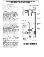
K. Sight Glass<br />
1. Maintenance<br />
The sight glass and water gauge set must be properly<br />
maintained in order to observe the boiler water level.<br />
Open the bottom drain cock (on the lower sight glass<br />
fixture) periodically to flush scale and sediment out of the<br />
sight glass.<br />
2. Regular Placement<br />
Replace the sight glass about every six months with new<br />
gaskets and brass washers. The continual movement of<br />
water through the water gauge set wears the sight glass.<br />
The combined effects of wear and high pressure cause<br />
small cracks to develop in the sight glass over a period of<br />
time. Eventually the sight glass will shatter. This is<br />
avoided by replacing the sight glass regularly.<br />
3. Gaskets & Washers<br />
When installing a new sight glass, also replace the<br />
gaskets and brass washers. If the brass washers are not<br />
in place, the gasket will twist, causing the glass to break.<br />
4. Proper Installation<br />
17<br />
the vent pipe from the condensate return tank. If there is<br />
an abnormally high steam flow from the vent, either the<br />
traps or check valves are leaking.<br />
L. External Inspections<br />
1. Maintenance<br />
External inspections are routine observations of the<br />
visible portions of the boiler. By noticing the normal<br />
boiler operation, many problems can be detected before<br />
they become serious.<br />
2. Piping<br />
Check the piping for leaks. This includes steam pipes,<br />
condensate pipes, feedwater pipes, blowdown pipes<br />
and all fittings on the boiler. If leaks are found, tighten<br />
the fittings or connections. If the pipe threads show<br />
extensive corrosion, replace the section of pipe.<br />
Remember, NEVER use galvanized pipe for a steam<br />
system or for condensate lines.<br />
3. Dust & Debris<br />
If dust, lint, or other debris collect on and around the<br />
boiler, then use pressurized air or a rag to clean the<br />
exterior surfaces. Also, it is very important to remove<br />
dust and debris that accumulate inside the boiler panel<br />
box. When working in and around the panel box always<br />
shut the power off at the circuit breaker or disconnect<br />
switch (do not use the boiler switch). Use an air hose to<br />
blow out the panel box and controls.<br />
4. Safety Valve<br />
Check that steam is not leaking from the safety valve. If<br />
the safety valve is not seating properly, then replace it<br />
with a new valve.<br />
5. Level Controls<br />
When making an external boiler inspection, it is also<br />
necessary to inspect the McDonnell Miller and auxiliary<br />
low water cut-off level controls. Disassemble the<br />
McDonnell Miller control per instructions in the<br />
Maintenance section. Check for scale build-up in the float<br />
chamber, around the float ball and the float rod. Check<br />
the float for leaks. Hold the float completely submerged<br />
in a bucket of water and look for air bubbles. If the float<br />
leaks or is damaged, it must be replaced. Remove the<br />
auxiliary low water cut-off probe and remove any scale<br />
that has deposited on the probe. Important: Inspect and<br />
clean all interconnecting piping on the auxiliary low water<br />
cut-off and the McDonnell Miller.<br />
6. Surface Rust<br />
Occasionally sheet metal surfaces will rust, especially<br />
near the stack. Water, a normal product of combustion,<br />
and the high temperatures present will cause rust.<br />
Perchloroethylene, used in dry cleaning, will accelerate<br />
corrosion. Check the entire length of the stack to be<br />
sure there is no leakage of combustion gases. Any rust<br />
appearing on the boiler jacket will only affect the boiler's<br />
appearance and should not harm the boiler operation.
Always be certain the sight glass is cut to proper length.<br />
Make sure the fixtures are plumb. If these two conditions<br />
are not checked, the glass may crack.<br />
M. Internal Inspections<br />
1. Purpose of Inspections<br />
Internal boiler inspections are required to check the<br />
structural integrity of the boiler shell and look for scale<br />
accumulations inside the boiler.<br />
2. New <strong>Boiler</strong> Inspection<br />
Make the initial inspection of a new boiler within 30 days<br />
of start-up. Depending on the condition of the boiler at<br />
this time, have a second inspection in six months or less.<br />
The results of these internal inspections can be used to<br />
set a time interval for future internal inspections.<br />
3. In Service <strong>Boiler</strong>s<br />
The time between inspections will vary from 180 days to<br />
one year. This depends on the amount and the quality of<br />
the boiler feedwater, and also on how the boiler is being<br />
used. If the boiler uses large quantities of untreated hard<br />
water, the boiler may need to be inspected every 60<br />
days. If the boiler uses minimal quantities of make-up<br />
water (i.e., closed loop systems) and the water is treated,<br />
the boiler may need to be inspected only once a year.<br />
Many state and/or city codes require annual internal<br />
boiler inspections.<br />
18<br />
4. Gaskets<br />
The hand hole gaskets and the McDonnell Miller head<br />
gasket must be replaced after each internal inspection.<br />
If any leaks are present around the gasket surfaces,<br />
replace the gasket immediately. High pressure water<br />
and steam leaks will erode the metal surfaces and<br />
cause damage to the boiler which will require expensive<br />
repairs. Keep a full set of hand hole gaskets and a<br />
McDonnell Miller head gasket in stock at all times.<br />
5. Sight Glass<br />
A sight glass with gaskets and washers should be kept<br />
in stock. Replace the sight glass with new gaskets and<br />
washers.<br />
6. Routine Service<br />
These standard maintenance items are considered<br />
routine and are not covered under warranty.
Section III: Maintenance<br />
WARNING: All maintenance procedures must be followed completely by competent personnel familiar with<br />
boilers and boiler accessories.<br />
CAUTION: Read and follow all instructions thoroughly before working on any boiler equipment.<br />
NOTE: Certain maintenance items concerning specific components may be found in the product literature<br />
specifications section of this manual.<br />
A. Daily Blowdown<br />
The boiler and controls may be blown down at any pressure<br />
but the blowdown lines must be piped to a safe location.<br />
<strong>Lattner</strong> recommends blowing down at 30 psi.<br />
1. <strong>Boiler</strong> Blowdown<br />
Turn the boiler blowdown valve to the full open<br />
position.<br />
Watch the sight glass. Let the water drop one<br />
inch in the sight glass. Approximately 10 to 12<br />
seconds.<br />
Shut the boiler blowdown valve.<br />
2. McDonnell Miller/Water Column Blowdown<br />
Turn the McDonnell Miller blowdown valve to<br />
the full open position.<br />
Leave the valve open for 3 to 5 seconds.<br />
Shut the water column blowdown valve.<br />
3. Auxiliary Low Water Blowdown (if applicable)<br />
Turn the auxiliary low water column blowdown<br />
valve to the full open position.<br />
Leave the valve open for 3 to 5 seconds.<br />
Shut the low water column blowdown valve.<br />
B. Weekly Maintenance<br />
1. Check the sight glass for excessive wear or leaks.<br />
2. Test the McDonnell Miller and auxiliary low water<br />
cut-off for proper operation. By opening the<br />
blowdown valves with the boiler firing, the burners<br />
must shut off during this test. If the burners do not<br />
shut off, the control may require immediate<br />
servicing.<br />
3. Drain the sight glass.<br />
4. Visually inspect the boiler and water feed system for<br />
any water or steam leaks in the piping.<br />
5. Check the vent pipe from the condensate return tank<br />
for excessive steam loss. This would indicate bad<br />
steam traps or check valves.<br />
19<br />
C. General Maintenance (Refer to Table 1, Page 20)<br />
1. Do the following every 6 to 12 months depending<br />
on water quality:<br />
Remove hand hole plate and clean inside<br />
boiler.<br />
Reassemble each hand hole with a new<br />
gasket.<br />
Clean McDonnell Miller float chamber.<br />
Reassemble the operating mechanism with a<br />
new head gasket.<br />
Clean scale off the auxiliary low water cut-off<br />
probe.<br />
Clean the interconnecting piping between the<br />
boiler and McDonnell Miller.<br />
Clean the interconnecting piping between the<br />
boiler and auxiliary low water column if<br />
applicable.<br />
2. Open the boiler for a complete internal inspection<br />
at least once a year.<br />
3. Replace the sight glass with gaskets and washers<br />
every six months or less if signs of wear appear.<br />
4. Rebuild or replace the check valves in the water<br />
feed line at least once a year. Always use springloaded<br />
check valves.<br />
5. Inspect the pilot burner and flame scanner for soot<br />
or dirt accumulations.
D. Table 1: Recommended Testing Schedule<br />
Item Frequency Responsibility Remarks<br />
Gauges and Sight Glass Daily Operator Make visual inspection and record readings in a log.<br />
Instrument and <strong>Boiler</strong> Settings Daily Operator Make visual check against manufacturer’s<br />
recommended specifications. Refer to product<br />
literature sheets.<br />
Low Water Fuel Cut-Off Monthly Operator Refer to manufacturer’s instructions.<br />
Pilot and Main Fuel Valves Monthly Operator Make visual inspection.<br />
Flame Failure Response Time Monthly Operator Close manual fuel valve supply. Check safety shutoff<br />
timing. Log results.<br />
Flame Signal Strength Monthly Operator If appropriate equipment is installed to measure<br />
flame signal, read and log results for pilot flame.<br />
Notify service organization if readings are high, low,<br />
or fluctuating.<br />
Hand Hole Plates Monthly Operator Visually check for leakage and replace gaskets as<br />
necessary.<br />
Firing Rate Control Annually Service Technician Verify BTU input and gas pressure and check with<br />
combustion test/analyzer.<br />
Igniter or Pilot Annually Operator Make visual inspection and check flame strength<br />
with appropriate equipment.<br />
Flue, Vent, and Stack Annually Operator Make visual inspection and check for proper<br />
operation.<br />
Pilot Turndown Test Annually Service Technician Required after any adjustments to pilot or gas<br />
pressure.<br />
High Limit Safety Control Annually Service Technician Refer to product literature.<br />
Operating Control Annually Service Technician Refer to product literature.<br />
Safety Valve As Required Operator In accordance with ASME <strong>Boiler</strong> and Pressure<br />
Vessel Code, “Recommended Rules for Care and<br />
Operation of Heating <strong>Boiler</strong>s”.<br />
20
E. Hand Hole Plate Removal & Re-Installation<br />
1. Disconnect all power to the boiler.<br />
2. The boiler must be cool and drained of all water.<br />
3. See assembly print for hand hole location.<br />
4. Remove the hand hole plate nut. Use a 7/8" socket.<br />
5. Remove arch over hand hole plate.<br />
6. Remove hand hole plate. Sometimes it is necessary<br />
to tap on the hand hole plate to loosen it. Make sure<br />
the hand hole plate does not fall inside the boiler.<br />
7. Scrape the inside of the boiler around the hand hole<br />
area to remove any scale or old gasket material.<br />
8. Scrape the old gasket material off the hand hole<br />
plate.<br />
9. Make sure there are no burrs around the hand hole<br />
opening. Remove any burrs with a file.<br />
10. Place the hand hole plate back into the boiler hand<br />
hole plate opening without the gasket. If the plate<br />
rocks back and forth, remove the high spots on the<br />
hand hole plate with a file. Note: Do not leave the<br />
hand hole plate installed without the gasket.<br />
11. Install the gasket on the hand hole plate. Make sure<br />
the gasket is pressed firmly down on to the hand<br />
hole plate. Do not use any grease, lubricants, or<br />
adhesives when installing handhold gaskets.<br />
12. Reinstall the hand hole plate into the boiler.<br />
13. Replace the arch over the stud of the hand hole<br />
plate. The arch should extend across the width<br />
(short way) of the hand hole opening.<br />
21<br />
14. Replace the nut on the hand hole plate stud.<br />
Tighten the nut hand tight, then turn the nut ¼ turn<br />
with a socket. Do not compress the gasket<br />
excessively. This will only shorten the life of the<br />
gasket.<br />
15. Reconnect the power to the boiler.<br />
16. Check the hand hole plate for leakage with<br />
pressure on the boiler. If leaks are noted, remove<br />
the pressure from the boiler, let the boiler cool and<br />
drain to reposition the hand hole plate. Repeat<br />
steps 12 through 16.
F. Sight Glass Removal & Re-Installation<br />
1. <strong>Boiler</strong> and pump should be switched off.<br />
2. <strong>Boiler</strong> should be cool and the water level should be<br />
below the lower water gauge fixture.<br />
3. Close the upper and lower water gauge valves.<br />
4. Loosen both sight glass packing nuts (top and<br />
bottom) with a wrench.<br />
5. Slide glass carefully upward into the upper fixture.<br />
Glass should lift out of the lower fixture.<br />
6. Pull glass down, out of the upper fixture tilting the<br />
glass slightly to clear the lower fixture. Be careful not<br />
to break the sight glass when removing.<br />
7. Assemble the new sight glass as shown. ALWAYS<br />
replace the gaskets and brass washers when<br />
installing a new sight glass.<br />
8. Slide the new glass into the upper fixture. Glass<br />
should clear the lower fixture and tilt into position.<br />
9. Slide the sight glass down into the lower fixture.<br />
Equalize the gap between the upper and lower<br />
fixtures.<br />
22<br />
10. Tighten the sight glass packing nuts hand tight.<br />
11. Use a wrench to tighten 1/4 turn past hand tight.<br />
NEVER over tighten the sight glass. This will crack<br />
the glass and cause it to shatter under pressure.<br />
12. Open the upper and lower gauge valves.<br />
13. Switch on boiler and pump.
G. McDonnell Miller Servicing<br />
1. Disconnect all power to the boiler.<br />
2. The boiler should be cool and drained of all water<br />
just below the McDonnell Miller control.<br />
3. Make sure all water is drained from the McDonnell<br />
Miller control by opening the control blowdown<br />
valve.<br />
4. Disconnect the wiring and conduit connection to the<br />
McDonnell Miller. Tag all wires to ensure they are<br />
reconnected properly.<br />
5. Remove the eight bolts holding the operating<br />
mechanism to the McDonnell Miller body. Use a<br />
9/16" wrench or a crescent wrench.<br />
6. It may be necessary to tap near the base of the<br />
operating mechanism to free it from the body.<br />
7. Lift the McDonnell Miller operating mechanism out of<br />
the body. Be careful to avoid damaging the float and<br />
float arm which extend into the body of the<br />
McDonnell Miller.<br />
8. Carefully scrape the old gasket from the body and<br />
the operating mechanism of the McDonnell Miller.<br />
9. Remove any scale in the McDonnell Miller body.<br />
Always check the operating mechanism for any<br />
scale that might be blocking the float or float arm.<br />
10. Check the float for any holes. Hold the float<br />
submerged in a bucket of water and look for any air<br />
bubbles coming from the float.<br />
11. Always reassemble the McDonnell Miller operating<br />
mechanism to the body with a new gasket.<br />
12. Reinstall the eight bolts to the operating mechanism.<br />
Draw up the bolts evenly to prevent damage to the<br />
gasket, body or operating mechanism. Do not over<br />
tighten the bolts.<br />
13. Reconnect the McDonnell Miller per wiring diagram.<br />
14. Reconnect all power to the boiler.<br />
15. Use a steel rod or a hard brush and clean inside of<br />
the piping.<br />
23<br />
16. Flush out all piping with water after cleaning.<br />
17. Replace all pipe plugs and pipe caps. Tighten with<br />
a wrench enough to prevent water or steam leaks.<br />
18. Reconnect power to the boiler.<br />
H. Cleaning Interconnecting Pipe (McDonnell Miller)<br />
1. Disconnect all power to the boiler.<br />
2. The boiler must be cool and drained of water below<br />
the level controls.<br />
3. Make sure all water is drained from the McDonnell<br />
Miller or auxiliary low water cut-off control by<br />
opening the blowdown valve.<br />
4. Clean all interconnecting piping by removing the<br />
pipe plugs or pipe caps. Remove all 1" pipe plugs<br />
with a 13/16" wrench or a crescent wrench.<br />
Remove the pipe caps with a pipe wrench.
I. Warrick Relay Replacement<br />
1. Disconnect all power to the boiler.<br />
2. Pull relay out by hand. This may take a little<br />
force but be careful.<br />
3. Replace the Warrick with a new 26M series<br />
Warrick. The relay has a small tab so that it<br />
can be installed only one way.<br />
4. Reconnect the power to the boiler.<br />
24<br />
J. Auxiliary Low Water Cut-Off Probe Cleaning<br />
1. Disconnect all power to the boiler.<br />
2. Remove the four screws on top of the probe<br />
enclosure with a Phillips screwdriver.<br />
3. Remove the wire from the probe using a 5/16"<br />
wrench or a crescent wrench. Only the wire on the<br />
probe is to be removed.<br />
4. Use a 13/16" spark plug socket and remove the<br />
probe.<br />
5. Clean the stainless steel probe and probe fitting.<br />
6. Reinsert the probe using a 13/16" spark plug<br />
socket. Only tighten the probe enough to stop any<br />
steam leaks. Over tightening will destroy the<br />
threads of the enclosure.<br />
7. Reinstall the probe wire to the probe.<br />
8. Reassemble the cover to the enclosure with the<br />
four Phillips screws.<br />
9. Reconnect power to the boiler.
Section IV: Troubleshooting<br />
WARNING: All troubleshooting procedures must be followed completely by competent personnel familiar with<br />
boilers and accessories.<br />
CAUTION: Read and follow all instructions before troubleshooting any boiler equipment.<br />
A. Normal Operation<br />
All <strong>Lattner</strong> forced draft gas-fired boilers follow the same<br />
operating sequence:<br />
1. Turn the pump switch ON.<br />
2. McDonnell Miller pump control turns on the pump or<br />
solenoid water valve.<br />
3. Pump or solenoid valve fills boiler.<br />
4. McDonnell Miller shuts off the pump or solenoid<br />
water valve when water is at normal operating level.<br />
5. Turn boiler switch to the ON position.<br />
6. Gas valve opens and main burners light.<br />
7. <strong>Boiler</strong> pressure will rise to the pressure controller’s<br />
set point. The then controller will shut off the gas<br />
valve.<br />
8. When the boiler calls for water, the McDonnell Miller<br />
level control will turn on the pump or solenoid water<br />
valve.<br />
9. If the pump cannot fill the boiler, the McDonnell<br />
Miller low water cut-off will shut down the boiler. If<br />
the McDonnell Miller does not shut down the boiler,<br />
the auxiliary low water cut-off will shut down the<br />
boiler.<br />
10. If the boiler has optional controls, refer to the wiring<br />
diagram.<br />
B. Basic Service Tools<br />
The following basic equipment will aid in troubleshooting<br />
<strong>Lattner</strong> boilers. Not all equipment is needed for every repair:<br />
1. Schematic diagram of the boiler<br />
2. Volt/ohm meter<br />
3. Ammeter<br />
4. Gas pressure gauge<br />
5. Flame simulator<br />
6. Continuity tester<br />
7. Flue gas analyzer<br />
8. Carbon monoxide sampler<br />
25<br />
C. Before You Begin<br />
Before you begin any troubleshooting procedures, check the<br />
following:<br />
1. Make sure the pilot is lit.<br />
2. Be certain boiler switch is on and that there are 115<br />
volts supplied to the boiler control circuit.<br />
3. Be certain pump switch is ON and check for proper<br />
pump voltage and phase if different from boiler<br />
circuit.<br />
4. Check if breaker is tripped or if fuse is blown.<br />
5. Make sure there is water in the boiler.<br />
6. Be certain manual gas cock is open and that gas is<br />
supplied to the boiler.<br />
7. Be certain that all manual resets have been<br />
pushed.<br />
Note: All <strong>Lattner</strong> boiler controls are wired in series.<br />
The boiler operating controls and limits form a series<br />
circuit. When all switches close, the boiler should fire.
Possible <strong>Boiler</strong> Problems Possible Causes<br />
<strong>Boiler</strong> and pump switch are ON,<br />
pump does not run and low water<br />
level in boiler.<br />
Pump runs but does not maintain<br />
water level in boiler.<br />
1. Circuit breaker is tripped or fuse is blown.<br />
2. McDonnell Miller piping is plugged.<br />
3. McDonnell Miller float is stuck.<br />
4. McDonnell Miller is wired incorrectly.<br />
5. Pump or solenoid water valve is wired incorrectly.<br />
1. Valve between boiler pump and boiler is closed.<br />
2. Bad check valve. Always replace check valves with spring-loaded check valves.<br />
3. Bad steam trap(s).<br />
4. Feedwater temperature is too high (pump is cavitating).<br />
5. Strainer is plugged.<br />
6. Pump isolation valve is closed.<br />
7. No water supplied to pump.<br />
Pump or solenoid overfills boiler. 1. Solenoid water valve is not seating properly.<br />
2. McDonnell Miller float operating incorrectly (snap switches “sticking”).<br />
3. McDonnell Miller mercury tube is malfunctioning.<br />
4. McDonnell Miller is wired incorrectly.<br />
5. Pump is wired incorrectly.<br />
<strong>Boiler</strong> takes excessive time to reach<br />
pressure.<br />
Limit switch always shuts down<br />
boiler.<br />
<strong>Boiler</strong> shuts down on auxiliary low<br />
water cut-off.<br />
Burner fails to start.<br />
Burner motor runs but pilot does not<br />
light.<br />
1. Burner is improperly adjusted.<br />
2. Improper gas pressure or insufficient supply of gas to boiler.<br />
3. <strong>Boiler</strong> flue passages need to be cleaned.<br />
4. Scale build-up inside boiler.<br />
5. Gas valves not operating properly.<br />
6. Pump not feeding enough water to the boiler.<br />
1. Operating pressure switch is set higher than limit switch.<br />
2. Scale build-up inside of boiler.<br />
3. Operating pressure switch (Honeywell “Controller”) is not operating correctly.<br />
1. Pump switch is turned OFF.<br />
2. Probe wired incorrectly.<br />
3. Probe has scale, dirt, or debris on it.<br />
4. Probe not seated in probe socket properly.<br />
5. Auxiliary level control relay wired incorrectly.<br />
6. Foaming problem in boiler (possible chemical over treatment).<br />
7. Water in boiler is too soft (possible water softener over treatment).<br />
8. McDonnell Miller primary low water cut-off isn’t operating properly.<br />
9. Pump is not functioning properly.<br />
10. Malfunctioning check valve. Always replace check valves with spring-loaded check<br />
valves.<br />
11. No water supplied to the pump.<br />
1. Bad fuse or switch open on incoming power source or motor overload out.<br />
2. Control circuit has an open control such as operating, limit, or low water cut-off.<br />
3. Reset button on motor or flame safeguard programming control open (push reset<br />
button).<br />
4. Loose or faulty wiring. Tighten all terminal screws. Check wiring against wiring diagram<br />
furnished with burner.<br />
5. Regulator vent plugged.<br />
1. Be sure gas is turned on at meter and pilot cock is open.<br />
2. Place hand on pilot valve to feel it open. Check gauge at tee in pilot line for gas<br />
pressure and prompt opening of pilot valve.<br />
3. Check visually or by sound for spark arcing.<br />
4. Check air switch. Be sure its circuit closes during start. Be sure timing card is inserted<br />
into flame safeguard.<br />
5. Bad igniter.<br />
6. Bad pilot solenoid valve.<br />
7. Pilot regulator vent plugged.<br />
26
Burner motor runs and pilot lights but<br />
main gas valve does not open.<br />
Occasional lockout for no apparent<br />
reason.<br />
Burner will not start even though<br />
burner has never failed before or has<br />
been running on normal cycle without<br />
failure.<br />
Flame Safeguard<br />
1. Check flame strength signal (digital display module). If low, adjust pilot gas pressure<br />
and air settings for improved readings.<br />
2. Possible dirty scanner lens.<br />
3. Check gas valve circuit, both main valve and proof of closure switch (if so equipped).<br />
4. Main valve opening too slow. Adjust bleed on diaphragm valve.<br />
5. Shut-off cock or test cock not open.<br />
6. Defective main valve.<br />
1. Re-check microamp or D.C. voltage readings. If sufficient, check gas pressure an air<br />
damper setting. Check electrodes setting. If flame rod pilot, flame rod may have to be<br />
re-positioned.<br />
2. Check ignition cable and electrode porcelain for damage or breaks which could cause<br />
short.<br />
3. Check for loose or broken wires.<br />
1. Operating control circuit open.<br />
2. Starting interlock such as proven low fire switch or proof of closure switch open.<br />
3. Defective control or loose wiring.<br />
4. Limit circuit open.<br />
For information on Honeywell flame safeguard and relay troubleshooting, refer to Honeywell<br />
technical literature number 65-0229-1.<br />
27
LATTNER BOILER LIMITED WARRANTY<br />
A <strong>Lattner</strong> boiler shell is guaranteed to be constructed in accordance with the ASME Code. An independent ASME<br />
boiler inspector inspects the construction of each boiler and: (1) checks mill test reports on all materials used to<br />
ensure that the chemical and physical analysis of such materials complies with the ASME Code; (2) inspects each<br />
boiler shell during construction to see that workmanship complies with the Code; and (3) witnesses the final<br />
hydrostatic test and then places the ASME stamp on the boiler shell and signs an ASME data report certifying the<br />
boiler is ASME approved.<br />
<strong>Lattner</strong> warrants the boiler and any other equipment of its manufacture to be free from defects in material and<br />
workmanship for one (1) year from the date of shipment from the factory, provided the boiler is operated under the<br />
normal use and service for which it was intended, and only if the boiler has been properly installed by a qualified<br />
technician in accordance with but not limited to ASME, ANSI, and NFPA Codes and applicable local, state, and<br />
national codes.<br />
<strong>Lattner</strong>’s obligation under this Warranty is limited, at <strong>Lattner</strong>’s option, to replacing or repairing any defective part<br />
of the boiler or other equipment it manufactures. No allowance will be made for labor, transportation, or other<br />
charges incurred in the replacement or repair of defective parts. Merchandise not manufactured by the <strong>Company</strong>,<br />
supplied in one piece or in component assemblies, is not covered by the above warranty, but the <strong>Company</strong> will<br />
give the Purchaser the benefit of such adjustment as it can make with the manufacturer of such items.<br />
<strong>Lattner</strong> shall not be liable for special, indirect, or consequential damages. <strong>Lattner</strong> shall not be liable for any loss or<br />
damage resulting, directly or indirectly, from the use or loss of use of the boiler. This exclusion from liability<br />
includes the Purchaser’s expenses for downtime or for making up downtime, damages for which the Purchaser<br />
may be liable to other persons, or damages to property.<br />
The remedies set forth in this Warranty are exclusive, and the liability of <strong>Lattner</strong> with respect to any contract or<br />
sale shall not exceed the cost of repair or replacement of the boiler or other equipment manufactured by <strong>Lattner</strong>.<br />
The above Warranty shall not apply to any boiler or other equipment manufactured by <strong>Lattner</strong> which:<br />
1) has been repaired or altered without <strong>Lattner</strong>’s written consent;<br />
2) has been altered in any way so as, in the judgment of <strong>Lattner</strong>, to adversely affect the stability or<br />
reliability of the boiler;<br />
3) has been subject to improper water treatment, scale, corrosion, misuse, negligence, or accident;<br />
4) has not been operated in accordance with <strong>Lattner</strong>’s printed instructions or specifications;<br />
5) has been operated under conditions more severe than or otherwise exceeding those set forth in the<br />
specifications for such boiler; or<br />
6) has not been properly installed by a qualified technical in accordance with but not limited to ASME,<br />
ANSI and NFPA Codes and all applicable local, state and national codes.<br />
THIS WARRANTY IS EXPRESSLY MADE IN LIEU OF ALL OTHER WARRANTIES, EXPRESS OR IMPLIED.<br />
LATTNER MAKES NO WARRANTY OF MERCHANTABILITY OR OF FITNESS FOR ANY PARTICULAR<br />
PURPOSE.<br />
Purchaser must notify <strong>Lattner</strong> of a breach of Warranty within thirty (30) days after discovery thereof, but not later<br />
than the one-year guarantee period; otherwise, such claims shall be deemed waived. No allowance will be<br />
granted for any repairs or alterations made by Purchaser without <strong>Lattner</strong>’s prior verbal or written consent. Items<br />
returned to <strong>Lattner</strong> must be accompanied by a factory-supplied return goods authorization (RGA). Such<br />
authorization may be obtained by calling the factory at 319/366-0778 or by writing to P.O. Box 1527, Cedar<br />
Rapids, IA 52406.<br />
<strong>Lattner</strong> neither assumes nor authorizes any person to assume for it any other liability in connection with the sale<br />
or use of the boiler or other equipment manufactured by <strong>Lattner</strong>, and there are no oral agreements or warranties<br />
collateral to or affecting this Agreement.<br />
LATTNER BOILER COMPANY<br />
Cedar Rapids, IA USA<br />
2-98-06
LIMITATION ON QUOTATION<br />
Unless otherwise stated in the quotation, the quotation will remain valid<br />
for a period of thirty (30) days from the date hereof, at which time it will<br />
automatically expire unless extended by a signed document issued by<br />
the <strong>Company</strong>, from its headquarters in Cedar Rapids, IA.<br />
EQUIPMENT SELECTION<br />
The Purchaser’s selection of sizes, types, capacities, and specifications<br />
and suitability thereof for the specific application shall be the unshared<br />
responsibility of the Purchaser or Purchaser’s representative or<br />
consultant.<br />
PERMISSABLE VARIATIONS, STANDARDS, AND TOLERANCES<br />
Except in the particulars specified by the Purchaser and expressly<br />
agreed to in writing by the <strong>Company</strong>, all materials shall be produced in<br />
accordance with the <strong>Company</strong>’s standard practices. The <strong>Company</strong><br />
reserves the right to deviate from tolerances and variations in the<br />
equipment without notice, provided that the substitute part(s) or<br />
deviation(s) are consistent with the usage and performance of the<br />
product.<br />
PRICES<br />
Unless defined otherwise in the quotation, prices are F.O.B. Cedar<br />
Rapids, IA USA, exclusive of freight, storage, off-loading, installation,<br />
service, start-up, extended warranty or local delivery charges, if any.<br />
TAXES<br />
Purchaser shall be liable for all Federal, State, and local taxes with<br />
respect to the purchase of the equipment proposed, unless exclusively<br />
exempted from any taxes and proof thereof is on file with the <strong>Company</strong>.<br />
PAYMENT<br />
Purchaser shall pay with US funds, the full amount of the invoiced<br />
purchase price within thirty (30) days of the <strong>Company</strong>’s invoice, whether<br />
the equipment has shipped or has been delayed through no fault of the<br />
<strong>Company</strong> and subject to approved credit. Beginning thirty (30) days after<br />
the invoice date, Purchaser shall pay a late payment charge of two<br />
percent (2%) per month, which is an annual rate of 24%, on any unpaid<br />
portion of the purchase price. The <strong>Company</strong> reserves the right to revoke<br />
or modify these credit terms.<br />
SHIPMENT<br />
Any shipping date shown in the body of the quotation or order<br />
acknowledgement, represents the <strong>Company</strong>’s approximated schedule as<br />
of the date of the quotation, and is subject to change as determined by<br />
shop loading if and when this quotation should be realized as an actual<br />
sale. The <strong>Company</strong> shall not incur any liability of any kind for failure to<br />
ship on any particular date unless a firm shipping date has been<br />
expressly agreed to by an officer of the <strong>Company</strong>, in a separate written<br />
document.<br />
CANCELLATION AND DELAYS<br />
Subsequent to the receipt of Purchaser’s Purchase Order and the<br />
<strong>Company</strong>’s issued order acknowledgement, the Purchaser may not<br />
change or cancel the order in whole or in part without the written<br />
approval and acceptance by the <strong>Company</strong> of such cancellation or<br />
change. The <strong>Company</strong> may condition its approval of a change or<br />
cancellation upon a price change to reflect the <strong>Company</strong>’s cost to<br />
implement the change, or to offset costs incurred by the <strong>Company</strong> in<br />
order preparation, engineering, purchasing, or in actual production of the<br />
order. In the event that the Purchaser delays shipment of the equipment<br />
upon the <strong>Company</strong>’s notice to ship, the equipment shall be placed in<br />
storage at the Purchaser’s risk and expense, and shall be invoiced as if<br />
shipped.<br />
RETURNS AND RESTOCKING<br />
Equipment may be returned to <strong>Lattner</strong> at 1411 9 th Street SW, Cedar<br />
Rapids, IA 52404, only upon prior written authorization of the <strong>Company</strong>.<br />
Consent, if given, will be upon the condition the Purchaser assumes all<br />
carrier charges, responsibility for damages in transit, and a minimum<br />
STANDARD TERMS & CONDITIONS<br />
LATTNER BOILER COMPANY<br />
Cedar Rapids, IA USA<br />
15% restocking charge, and only if the authorized material is in new and<br />
unused condition and returned within one year from original date of<br />
shipment. The credit will be based on the original invoice price or the<br />
current price; whichever is lower, less the applicable restocking charge.<br />
SECURITY INTEREST<br />
For the purposes of securing payment, the <strong>Company</strong> may issue a lien on<br />
the equipment, for past due accounts, until such time that payment has<br />
been received in full. Upon receipt of payment in full, the <strong>Company</strong> will<br />
rescind the lien.<br />
FORCE MAJEURE<br />
In no event shall the <strong>Company</strong> be liable for loss or damage resulting<br />
from any delay or failure to ship or other failure, loss, or damage that is<br />
the proximate result of any act of government authority, revolution, riot,<br />
civil disorder, act of war, delay or default in transportation, inability to<br />
obtain materials or facilities from normal sources, fire, flood, act of God,<br />
or any cause not within the reasonable control of the <strong>Company</strong>. The<br />
<strong>Company</strong> may, without causing a breach or incurring liability, allocate<br />
goods which are in short supply irrespective of the reasons therefore<br />
among customers in any manner which the <strong>Company</strong> in its sole<br />
discretion deems advisable. If an event occurs that is beyond the control<br />
of the <strong>Company</strong>, and that event delays the <strong>Company</strong>’s performance and<br />
causes its cost of production to increase because of the delay, the<br />
<strong>Company</strong> may pass such increased cost(s) on to the Purchaser.<br />
DAMAGE LIMITATION<br />
Under no circumstance shall the <strong>Company</strong> be held liable for any loss of<br />
profits, down time, or any incidental or consequential damages of any<br />
kind with respect to its products or the transaction by which its products<br />
are sold.<br />
WARRANTY AND PERFORMANCE<br />
Products shall be warranted in accordance with the <strong>Company</strong>’s standard<br />
warranty statement, form No. 2-98-R06. The <strong>Company</strong>’s warranty shall<br />
be voided by any abuse, misuse, neglect, unauthorized modification or<br />
service, lack of maintenance and service, or use not in accordance with<br />
the <strong>Company</strong>’s instructions. Warranty shall also be voided if water<br />
treatment has not been provided or by improper start-up of the<br />
equipment. The <strong>Company</strong>’s warranty statement and this paragraph<br />
contain the <strong>Company</strong>’s sole warranty and the <strong>Company</strong> makes no<br />
implied warranty, and there is no implied warranty of merchantability or<br />
fitness for any particular purpose.<br />
SERVICE<br />
Unless otherwise noted herein, the cost of the equipment does not<br />
include service or installation. All services performed by the <strong>Company</strong><br />
are subject to the Purchaser’s payment of the <strong>Company</strong>’s prevailing<br />
charges plus necessary travel and living expenses. Whenever service is<br />
quoted, please refer to <strong>Lattner</strong>’s Service Policy for specific details.<br />
EXCLUSION OF OTHER TERMS<br />
This constitutes an offer on behalf of <strong>Lattner</strong> <strong>Boiler</strong> Manufacturing (the<br />
<strong>Company</strong>); to sell the goods described in the quotation, exclusively on<br />
the terms and conditions stated. Acceptance of this by the Purchaser is<br />
hereby expressly limited to these Terms and Conditions and shall be<br />
applicable to any order issued by the Purchaser unless other terms have<br />
been agreed to in a written document issued by the <strong>Company</strong>.<br />
GOVERNING LAW<br />
The transaction with respect to the goods, which are subject hereof, shall<br />
be governed by, interpreted, and construed in accordance with the laws<br />
of the State of Iowa. The Courts in the State of Iowa will have the sole<br />
jurisdiction over any claim arising under this contract of sale.<br />
ASSIGNMENT<br />
All sales as evidenced by the <strong>Company</strong>’s acknowledgement shall be<br />
binding upon and insure to the benefit of the Purchaser and the<br />
<strong>Company</strong> and their respective heirs, successors, or assigns.<br />
TC06
48<br />
Easy Topog-E® <strong>Boiler</strong> Installation Instructions<br />
1. Remove old gasket and thoroughly clean the surface on boiler and on cover plate.<br />
Sometimes it is necessary to buff each surface.<br />
2. Place Topog-E® Gasket on handhole cover plate. Be sure the gasket is pushed down<br />
tight on the plate. Do not use any grease, lubricant, or adhesive.<br />
3. After cover plate is in boiler and gasket is in place, make one last cleaning swipe of the<br />
mating surface in the boiler. Use a rag wrapped around your finger.<br />
4. Set crab, then center plate in opening and tighten nut enough to give a snug fit. Then,<br />
snug up with 1/4 turn of wrench.<br />
SPECIAL NOTES:<br />
• If gasket leaks while pressure is being built up, tighten only enough to stop leakage.<br />
Never over-compress a gasket.<br />
• Gaskets on the bottom of a boiler shell are usually hard to install without leaking<br />
because particles of scale or sand tend to run down onto the mating surface between<br />
the time the surface is cleaned and the handhole cover plate is put into place ready<br />
<strong>Lattner</strong> <strong>Boiler</strong> <strong>Company</strong><br />
Instruction Manual – <strong>WLF</strong> <strong>Model</strong>s<br />
February 2005<br />
Page 30
49<br />
to be tightened. When this happens, drain the boiler again and start over, or expect<br />
to replace the gasket in a very short time.<br />
• As pressure builds up in the boiler the bolt and crab will loosen. It takes some time<br />
for the gasket to reach its ultimate compression, so the operator should watch this<br />
for several days and keep the bolt tight until it no longer loosens. This is especially<br />
true if the boiler is operated intermittently; i.e., shut off at night to allow pressure to<br />
drop. In this case, vacuum pressure in the boiler would suck the cover plate in and<br />
allow the water to leak out of the boiler.<br />
• Re-using gaskets after they have been in service is not recommended!<br />
Topog-E® Bolt Gaskets (when required) should be used with Topog-E®<br />
Handhole Gaskets.<br />
Topog-E® Gaskets are sold for use in steam, water, air, and other selected applications<br />
only. Recommendations for use of Topog-E Gaskets are based on tests believed to be<br />
reliable and on actual customer experience. Since their installation and use is beyond<br />
our control we cannot guarantee the results, whether or not such use is in accordance<br />
with directions. We disclaim any responsibility.<br />
1224 North Utica<br />
Tulsa, OK 74110-4682<br />
1-800-587-7123<br />
918-587-6649<br />
Fax: 918-587-6961<br />
topogesales@topog-e.com<br />
<strong>Lattner</strong> <strong>Boiler</strong> <strong>Company</strong><br />
Instruction Manual – <strong>WLF</strong> <strong>Model</strong>s<br />
February 2005<br />
Page 31
Page 32
Page 33
Page 34
Page 35
Page 36
Page 37
Page 38
Page 39
Page 40
Page 41
Page 42
Page 43
Page 44
Page 45
KUNKLE PRESSURE RELIEF VALVES<br />
Installation and Operating Instructions<br />
Pre-Installation Handling<br />
This pressure relief valve is designed to protect equipment from overpressure. The valve should be handled with care, not<br />
subjected to heavy shock loads, and protected to prevent contamination from getting inside. It should be installed correctly per<br />
A.S.M.E. <strong>Boiler</strong> & Pressure Vessel Code requirements. Failure to do so could result in property damage or serious injury to<br />
personnel. When hoisting the valve into position for installation, care should be exercised so that lifting straps do not contact<br />
the valve lift lever.<br />
Installation<br />
Always wear proper safety equipment, including safety glasses and ear protection.<br />
1. Mount the valve in a vertical position so that the valve body is self-draining. If a body drain port is provided, make sure it is<br />
open when required by the ASME code. Do not plug any bonnet vent openings. The inlet piping should be as short as<br />
possible, with no elbows, and equal to or greater than the size of the pressure relief valve inlet connection. This will help to<br />
limit the inlet pressure drop to 3% or less when the valve is relieving.<br />
2. When discharge piping is connected to valve outlet, make sure it is self draining if a body drain port is not used. The valve<br />
should not be connected to any discharge pipe that contains pressure before the valve opens or to any pipe where the<br />
pressure build-up is greater than 10% of the set pressure when the valve is open and relieving.<br />
Discharge piping, other than a short tailpipe, must be supported. For steam service, a drip pan elbow or flexible connection<br />
between the valve and the pipe should be used to prevent excessive pipe stress, due to thermal expansion, from being<br />
imposed on the valve body.<br />
3. For threaded valves, to prevent sealing compound from entering and damaging the valve, apply a small amount of pipe<br />
thread sealing compound to external threads only. Do not put any sealing compound on the first thread or on any internal<br />
threads. To do so may cause the sealing compound to enter the valve and cause seat leakage.<br />
Do not use the valve body or bonnet for installing the valve in threaded connections. Use the wrench flats provided to<br />
tighten the valve to the connecting pipe, and do not overtighten. To do so may cause valve leakage.<br />
4. For flanged valves, use new gaskets and tighten the mounting studs evenly.<br />
Operation<br />
1. Maintain a system operating pressure at least 5 psig or 10% below the set pressure of the valve, whichever is greater.<br />
Operating too close to the valve set pressure will cause seat leakage and will shorten the time between valve maintenance.<br />
2. Do not use the safety valve as a control valve to regulate system operating pressure. Excessive operation will cause the<br />
seat to leak and will require more frequent valve maintenance.<br />
3. ASME Section I and VIII valves equipped with lift levers are designed to be operated only when the system pressure is<br />
75% of set pressure or greater. ASME Section IV valves may be operated at any set pressure. When hand operating the<br />
valve, hold it open long enough to purge any foreign matter from the seat area. If a cable or wire is attached to the lift lever<br />
for remote actuation, make sure the direction of pull is the same as it would be if the lever were pulled directly by hand.<br />
Maintenance<br />
Maintenance should be performed on a regular basis. An initial inspection interval of 12 months is recommended. Depending<br />
on the service conditions and the condition of the valve, the inspection interval may be decreased or increased. Use only<br />
Kunkle parts for repair. Depending on the local jurisdictional requirements where the valve is installed, repairs may have to be<br />
made by a repair facility holding a VR stamp.<br />
WARNING!<br />
Removal of the seal wires or any attempt to adjust, repair or modify this product by non-qualified or non-authorized persons<br />
voids the product guarantee and may cause serious damage to equipment, personal injury, and death. Kunkle Valve is not<br />
liable for any damage resulting from misuse or misapplication of its products.<br />
Kunkle Valve Division Rev B 01/14/2002<br />
Phone: 828-669-5515 953 Old US 70, Black Mountain, NC 28711 Fax: 828-669-4017<br />
Page 46
Gas Appliance<br />
Pressure Regulators<br />
Straight-Thru-Flow Design<br />
design certified<br />
S-T-F Series<br />
BULLETIN MS2056- 04/04<br />
RV52, RV53, RV61, RV81, RV91, RV111, and RV131<br />
1/2", 3/4", 1", 1¼", 1½", 2", 2½", 3" & 4"<br />
Maximum Pressure<br />
CSA Rated (except RV131) .......... 1/2 psi (35 mbar)<br />
Maxitrol Tested*<br />
RV52 & RV53 .......................... 1/2 psi (35 mbar)<br />
RV61, RV81, RV91, & RV111 ....... 1 psi (70 mbar)<br />
RV131 ................................... 2 psi (140 mbar)<br />
* Do not use if inlet pressure is more than 10 times<br />
desired outlet pressure<br />
EMERGENCY EXPOSURE LIMITS (Maxitrol Tested)<br />
RV52 & RV53 .......................... 3 psi (210 mbar)<br />
RV61, RV81, RV91 & RV111 ........ 5 psi (350 mbar)<br />
RV131 ................................... 15 psi (1050 mbar)<br />
GAS CONTAINMENT EXPOSURE LIMITS*<br />
RV 52 & RV53 ......................... 15 psi (1050 mbar)<br />
RV61, RV81, RV91, RV111,<br />
& RV131 ................................ 25 psi (1750 mbar)<br />
* Please note that internal damage may occur when<br />
exposed to these pressures.<br />
AMBIENT TEMPERATURE LIMITS<br />
RV52, RV53, RV61, RV81,<br />
RV91 & RV111 ............... -40° to 205° F (-40° to 96° C)<br />
RV131 ......................... -40 to 125° F (-40 to 52° C)<br />
...........................................<br />
GASES: Natural, manufactured, mixed, liquefied<br />
petroleum, or LP gas-air mixture.<br />
Page 47
Straight-Thru-Flow Design<br />
All models except RV131 are CSA design certified for 1/<br />
2 psi rated pressure under the ANSI standard for gas<br />
pressure regulators; and CSA listed to certify compliance<br />
with nationally published safety, construction, and<br />
performance standards.<br />
They are main burner only, non-lockup type. They<br />
should not be used as a line gas pressure regulator<br />
ahead of low pressure controls. Use only where<br />
downstream controls can operate at line pressure.<br />
Refer to other Maxitrol sales bulletins for proper<br />
types.<br />
The RV52, RV53, & RV61 are suitable for multipoise<br />
mounting. The RV81, RV91, RV111, & RV131 are<br />
recommended for normal horizontal position only.<br />
Maxitrol's original Straight-Thru-Flow design meets<br />
your needs for high capacities at low inlet pressures.<br />
The basic difference between S-T-F design and other<br />
type regulators lies in the conical valve. The cone<br />
principal permits gas to flow straight through the<br />
regulator without changing directions. Frictional flow<br />
resistance is reduced, resulting in greater capacity.<br />
The improved flow pattern provides accurate<br />
sensitive regulation at extremely low pressure<br />
differentials. The ability of the regulator to handle<br />
large capacity appliances with limited supply<br />
pressure offers a definite advantage to designers of<br />
commercial and industrial gas-fired equipment.<br />
<strong>Model</strong>s up to the three inch pipe size have high<br />
strength pressure cast aluminum housings. The<br />
2<br />
RV52, RV53, RV61, RV81,<br />
RV series RV91, RV111, and RV131<br />
FEATURES<br />
• Greater accuracy—higher pressure drop capacity<br />
• Outlet pressures available to 42” w.c.<br />
• Available in full range of pipe sizes from 1/2"<br />
to 4"<br />
• All models tapped with NPT vent bosses<br />
• CSA Design Certified (except RV131)<br />
BENEFITS<br />
• Unique conical valve design fills need of combining<br />
good regulation with high capacity in low to<br />
intermediate pressure range<br />
• Allows more pressure drop to be assigned to piping<br />
and valves—permits reduction in manifold size<br />
• Provides accurate, sensitive regulation at inlet<br />
pressures as low as 3” w.c.<br />
• RV131 only, provides bonus benefits of high capacity<br />
and good performance at pressures of 1 psi or higher<br />
• Ease of installation and replacement<br />
RV131 four inch model is of cast iron and steel<br />
construction. RV61, RV81, RV91, RV111, & RV131<br />
internal conical valves are coated with Teflon ® for<br />
long life. Diaphragm material is cut from the finest<br />
synthetic coated fabrics available. All other parts are<br />
carefully specified corrosion-resistant or plated<br />
material.<br />
Pipe sizes of 1/2”, 3/4”, 1”, 1-1/4”, 1-1/2”, 2”, 2-1/2",<br />
3”, and 4” are available. <strong>Model</strong>s through the 3" size<br />
are threaded, the 4" RV131 is flanged.<br />
At the emergency exposure limits, there may be no<br />
regulation, but all models will contain gas. They will<br />
suffer no internal damage and will resume regulation<br />
when normal pressure is restored.<br />
Straight-Thru-Flow appliance regulators are intended<br />
for use with all fuel gases, and may also be used with<br />
air or other noncorrosive gases within their pressure<br />
limits.<br />
Typical applications include all types of residential,<br />
commercial and industrial gas-fired appliances and<br />
equipment used on low pressure gas supply. See<br />
Maxitrol’s ”Spring Selection Chart“ for part numbers,<br />
color and size of springs.<br />
Teflon is a registered trademark of DuPont Corporation.<br />
NOTE: All Maxitrol appliance regulators should be installed<br />
in accordance with Maxitrol’s “Safety Warning” bulletin.<br />
Page 48
Capacities and Pressure Drop<br />
CAPACITIES—expressed in CFH (m 3 /h)—0.64 sp gr gas<br />
<strong>Model</strong><br />
Number and Pipe Size<br />
RV52<br />
RV53<br />
RV61<br />
RV81<br />
RV91<br />
RV111<br />
1/2 x 1/2<br />
3/4 x 3/4<br />
3/4 x 3/4<br />
1 x 1<br />
1 x 1<br />
1-1/4 x 1-1/4<br />
1-1/4 x 1-1/4<br />
1-1/2 x 1-1/2<br />
2 x 2<br />
2-1/2 x 2-1/2<br />
2-1/2 x 2-1/2<br />
3 x 3<br />
A.G.A. CSA<br />
MAX<br />
450<br />
(12.7)<br />
710<br />
(20.1)<br />
1100<br />
(31.1)<br />
2500<br />
(70.8)<br />
3275<br />
(92.7)<br />
7500<br />
(212)<br />
RV131 4 x 4 --<br />
Sizing Instructions<br />
In order to select the proper size regulator, you must<br />
know the available inlet pressure, desired outlet<br />
pressure, and the required maximum flow rate.<br />
Example No. 1—To select a regulator of ample<br />
capacity to handle flow.<br />
KNOWN:<br />
Pipe size 2-1/2", flow rate 8,000 CFH (0.64 sp gr), inlet<br />
pressure 9" w.c., desired outlet pressure 5" w.c.<br />
SOLUTION:<br />
1. Determine differential pressure available:<br />
Inlet pressure 9" w.c.<br />
Subtract outlet pressure - 5" w.c.<br />
Available differential pressure 4" w.c.<br />
2. When determining capacity Maxitrol<br />
recommends that the pressure drop not exceed<br />
1/2 of available differential pressure (1/2 of 4"<br />
w.c. = 2" w.c.).<br />
3. Check Capacity Chart to determine which<br />
regulator has a pressure drop of 2" w.c. or less at<br />
a flow rate of 8,000 CFH.<br />
4. The RV111 meets these standards with a<br />
flow rate of 12,134 CFH for the 2-1/2" pipe size at<br />
2" w.c. pressure drop. The 2-1/2" RV91 flows<br />
5422 CFH at 2" w.c. pressure drop. Therefore, the<br />
RV111—2-1/2" is the correct regulator to use.<br />
Example No. 2—To determine maximum<br />
recommended operating outlet pressure.<br />
KNOWN:<br />
Pipe size 4", flow rate 21,000 CFH, inlet pressure<br />
10" w.c.<br />
Pressure DropÑinches w.c. (mbar)<br />
0.1 0.2 0.3 0.4 0.5 0.6 0.7 0.8 0.9 1 2 3 4<br />
151<br />
(4.2)<br />
217<br />
(6.1)<br />
379<br />
(10.7)<br />
780<br />
(22.1)<br />
1212<br />
(34.3)<br />
2742<br />
(78)<br />
4734<br />
(134)<br />
214<br />
(6.1)<br />
306<br />
(8.6)<br />
536<br />
(15.1)<br />
1102<br />
(31.2)<br />
1714<br />
(48.5)<br />
3878<br />
(110)<br />
6695<br />
(190)<br />
262<br />
(7.4)<br />
375<br />
(10.6)<br />
675<br />
(19.1)<br />
1350<br />
(38.2)<br />
2100<br />
(59.4)<br />
4750<br />
(134)<br />
8200<br />
(232)<br />
302<br />
(8.5)<br />
433<br />
(12.2)<br />
759<br />
(21.5)<br />
1559<br />
(44.1)<br />
2424<br />
(68.6)<br />
5485<br />
(155)<br />
9468<br />
(268)<br />
338<br />
(9.5)<br />
484<br />
(13.7)<br />
848<br />
(24)<br />
1743<br />
(49.5)<br />
2711<br />
(76.7)<br />
6132<br />
(175)<br />
10586<br />
(300)<br />
370<br />
(10.5)<br />
530<br />
(15)<br />
929<br />
(26.3)<br />
1909<br />
(54)<br />
2969<br />
(84.1)<br />
6718<br />
(190)<br />
11596<br />
(328)<br />
3<br />
400<br />
(11.3)<br />
573<br />
(16.2)<br />
1004<br />
(28.4)<br />
2062<br />
(58.4)<br />
3208<br />
(90.8)<br />
7256<br />
(205)<br />
12525<br />
(354)<br />
427<br />
(12.1)<br />
612<br />
(17.3)<br />
1073<br />
(30.4)<br />
2204<br />
(62.4)<br />
3429<br />
(97.1)<br />
7757<br />
(219)<br />
13390<br />
(380)<br />
453<br />
(12.8)<br />
650<br />
(18.4)<br />
1138<br />
(32.2)<br />
2339<br />
(66.2)<br />
3637<br />
(103)<br />
8227<br />
(233)<br />
14202<br />
(402)<br />
478<br />
(13.5)<br />
684<br />
(19.3)<br />
1200<br />
(34.0)<br />
2465<br />
(69.8)<br />
3834<br />
(108)<br />
8572<br />
(243)<br />
14971<br />
(424)<br />
676<br />
(19.1)<br />
968<br />
(27.4)<br />
1742<br />
(49.3)<br />
3485<br />
(98.7)<br />
5422<br />
(153)<br />
12134<br />
(343)<br />
21172<br />
(600)<br />
SOLUTION:<br />
1. Check capacity Chart above for 4" regulator,<br />
RV131.<br />
2. Note that at a flow rate of 21,172 CFH the<br />
pressure drop is 2" w.c.<br />
3. Multiply this by two to obtain recommended<br />
differential pressure (4" w.c.).<br />
4. Subtract 4" differential pressure from 10" w.c.<br />
inlet pressure to obtain maximum recommended<br />
outlet pressure setting of 6" w.c.<br />
Pressure Drop Chart<br />
828<br />
(23.4)<br />
1185<br />
(33.5)<br />
2134<br />
(60.4)<br />
4269<br />
(120)<br />
6640<br />
(188)<br />
14862<br />
(420)<br />
25930<br />
(734)<br />
956<br />
(27.1)<br />
1369<br />
(38.7)<br />
2464<br />
(69.8)<br />
4929<br />
(139)<br />
7668<br />
(217)<br />
17161<br />
(486)<br />
29942<br />
(848)<br />
Page 49
Dimensions and Spring Ranges<br />
RV52 & 53<br />
C<br />
DIMENSIONS*—inches (millimeters)<br />
<strong>Model</strong> &<br />
Illustration<br />
Number<br />
RV52<br />
RV53<br />
RV61<br />
RV81<br />
RV91<br />
2" pipe<br />
RV91<br />
2.5" pipe<br />
RV111<br />
RV131<br />
D<br />
B<br />
A<br />
* Dimensions are to be used only as an aid in designing clearance for the valve.<br />
Actual production dimensions may vary somewhat from those shown.<br />
SPRING SELECTION CHART—inches w.c. (mbar)<br />
<strong>Model</strong><br />
Number<br />
RV52<br />
RV53<br />
RV61<br />
RV81<br />
RV91<br />
RV111<br />
RV131<br />
Vent<br />
Tap<br />
1/8"<br />
NPT<br />
1/8"<br />
NPT<br />
1/8"<br />
NPT<br />
3/8"<br />
NPT<br />
1/2"<br />
NPT<br />
1/4"<br />
NPT<br />
3/4"<br />
NPT<br />
3/4"<br />
NPT<br />
RV61<br />
NOTE: The area within the heavy line indicates CSA certified springs.<br />
A copyrighted publication of<br />
Swing<br />
Radius<br />
3.6<br />
(91)<br />
3.9<br />
(99)<br />
4.8<br />
(122)<br />
6.4<br />
(162)<br />
8.5<br />
(216)<br />
8.3<br />
(212)<br />
11.5<br />
(284)<br />
18.2<br />
(462)<br />
www.maxitrol.com<br />
C<br />
D<br />
Call-Outs<br />
A B C D<br />
4.9<br />
(124)<br />
5.2<br />
(132)<br />
6.4<br />
(164)<br />
8.4<br />
(213)<br />
10.8<br />
(275)<br />
10.5<br />
(267)<br />
15.1<br />
(373)<br />
23.25<br />
(590)<br />
3.2<br />
(81)<br />
3.75<br />
(95)<br />
4.4<br />
(111)<br />
6<br />
(153)<br />
6.5<br />
(165)<br />
7.1<br />
(181)<br />
9<br />
(229)<br />
13.9<br />
(353)<br />
3.25<br />
(83)<br />
3.9<br />
(99)<br />
5.4<br />
(138)<br />
7<br />
(178)<br />
9.1<br />
(232)<br />
9.1<br />
(232)<br />
13.4<br />
(324)<br />
18<br />
(458)<br />
B<br />
1.25<br />
(32)<br />
1.3<br />
(33)<br />
1.6<br />
(41)<br />
2<br />
(51)<br />
2.3<br />
(60)<br />
2.4<br />
(62)<br />
3.5<br />
(89)<br />
5.1<br />
(129)<br />
A<br />
RV81 & 91<br />
C<br />
C<br />
RV111<br />
C<br />
RV131<br />
A.G.A. CSA Certified Springs Other Springs Available<br />
3 to 6<br />
(7.5-15)<br />
3 to 6<br />
(7.5-15)<br />
3 to 6<br />
(7.5-15)<br />
3 to 6<br />
(7.5-15)<br />
3 to 6<br />
(7.5-15)<br />
3 to 6<br />
(7.5-15)<br />
3 to 6<br />
(7.5-15)<br />
4-8<br />
(10-20)<br />
4-8<br />
(10-20)<br />
4-8<br />
(10-20)<br />
4-8<br />
(10-20)<br />
4-8<br />
(10-20)<br />
4-8<br />
(10-20)<br />
--<br />
5-12<br />
(12.5-30)<br />
5-12<br />
(12.5-30)<br />
5-12<br />
(12.5-30)<br />
5-12<br />
(12.5-30)<br />
5-12<br />
(12.5-30)<br />
5-12<br />
(12.5-30)<br />
5-12<br />
(12.5-30)<br />
1-3.5<br />
(2.5-9)<br />
1-3.5<br />
(2.5-9)<br />
1-3.5<br />
(2.5-9)<br />
1-3.5<br />
(2.5-9)<br />
1-3.5<br />
(2.5-9)<br />
1-3.5<br />
(2.5-9)<br />
--<br />
2-5<br />
(5-12.5)<br />
2-5<br />
(5-12.5)<br />
2-5<br />
(5-12.5)<br />
2-5<br />
(5-12.5)<br />
2-5<br />
(5-12.5)<br />
2-5<br />
(5-12.5)<br />
2-5<br />
(5-12.5)<br />
3-8<br />
(7.5-20)<br />
3-8<br />
(7.5-20)<br />
3-8<br />
(7.5-20)<br />
3-8<br />
(7.5-20)<br />
3-8<br />
(7.5-20)<br />
3-8<br />
(7.5-20)<br />
3-8<br />
(7.5-20)<br />
4-12<br />
(10-30)<br />
4-12<br />
(10-30)<br />
-- --<br />
4-12<br />
(10-30)<br />
4-12<br />
(10-30)<br />
4-12<br />
(10-30)<br />
4-12<br />
(10-30)<br />
D<br />
D<br />
D<br />
-- -- -- --<br />
-- -- -- --<br />
5-15<br />
(12.5-38)<br />
5-15<br />
(12.5-38)<br />
5-15<br />
(12.5-38)<br />
--<br />
10-22<br />
(25-55)<br />
10-22<br />
(25-55)<br />
10-22<br />
(25-55)<br />
10-22<br />
(25-55)<br />
10-22<br />
(25-55)<br />
B<br />
European Representatives<br />
Warnstedter Strasse 3 06502 Thale, Germany<br />
49.3947.400.0 • Fax 49.3947.400.200<br />
Industriestrasse 1 48308 Senden, Germany<br />
49.2597.9632.0 • Fax 49.2597.9632.99 Page 50<br />
B<br />
B<br />
-- --<br />
-- --<br />
-- --<br />
-- --<br />
15-30<br />
(38-75)<br />
Maxitrol <strong>Company</strong><br />
23555 Telegraph Rd., P.O. Box 2230<br />
Southfield, MI 48037-2230 U.S.A.<br />
248.356.1400 • Fax 248.356.0829<br />
A<br />
A<br />
20-42<br />
(50-105)<br />
A
SAFETY WARNING INSTRUCTIONS<br />
FOR MAXITROL GAS PRESSURE REGULATORS<br />
NOTE: GAS PRESSURE REGULATORS WILL NOT<br />
TURN OFF THE FLOW OF GAS.<br />
SPECIAL WARNINGS<br />
IF YOU DO NOT FOLLOW THESE INSTRUCTIONS EXACTLY, A<br />
FIRE OR EXPLOSION MAY RESULT CAUSING PROPERTY<br />
DAMAGE, PERSONAL INJURY OR LOSS OF LIFE.<br />
NO UNTRAINED PERSON SHOULD ATTEMPT TO INSTALL,<br />
MAINTAIN OR SERVICE GAS PRESSURE REGULATORS.<br />
To minimize the possibility of FIRE, EXPLOSION, and OTHER HAZARDS:<br />
1. All products, including gas pressure regulators, used with combustible<br />
gas must be installed and used strictly in accordance with the instructions<br />
of the manufacturer, with government codes and regulations, and plumbing<br />
codes and practices.<br />
2. Do not use a gas pressure regulator if it appears to have been subjected<br />
to high temperatures, damaged in any way, or to have been taken apart or<br />
tampered with. Any of these may be signs of possible leakage or other<br />
damage that may affect proper operation and cause potentially dangerous<br />
combustion problems<br />
3.<br />
a. Install the regulator properly with gas flowing as indicated by the arrow<br />
on the casting.<br />
b. Use pipe compound or thread sealant, properly threaded pipes and<br />
careful assembly procedure so that there is no cross threading, etc.,<br />
which might cause damage or leakage.<br />
c. Apply wrench or vise pressure only to the flat areas around the<br />
pipe tappings at the end being threaded to the pipe to avoid possible<br />
fracture of the regulator body which could result in leakage<br />
d. Make sure markings or wording on regulator are not painted over or<br />
obliterated.<br />
4. Check carefully for gas leaks immediately after the regulator has been<br />
installed and the gas turned on. Do this before attempting to operate the<br />
appliance or other gas burning device. Use a rich soap solution (or other<br />
accepted leak tester) around the diaphragm flanges, bottom plate, vent<br />
opening, seal cap, pipe connections, and all other joints. Wipe clean with a<br />
damp rag. It is a good practice to periodically check for leakage during use<br />
of the appliance. Absolutely no leakage should occur, otherwise there<br />
is a danger of fire or explosion depending upon conditions. Never use<br />
if leakage is detected.<br />
CAUTION<br />
NEVER CONNECT REGULATOR DIRECTLY TO THE PROPANE<br />
SUPPLY SOURCE. MAXITROL REGULATORS REQUIRE AN<br />
EXTERNAL REGULATOR (NOT SUPPLIED). INSTALL THE<br />
EXTERNAL REGULATOR BETWEEN THE PROPANE SUPPLY<br />
SOURCE AND MAXITROL REGULATOR.<br />
5. Very high pressure surges in the gas supply line (or as a result of exposing<br />
the system to high pressure) may result in serious internal damage and<br />
cause leakage or affect regulator operation. If you suspect that a Maxitrol<br />
regulator has been exposed to more than twice the maximum operating<br />
inlet pressure, as shown in the following chart, turn off the gas and have<br />
the system checked by an expert.<br />
(over)<br />
INSTRUCCIONES PARA PRECAUCIONES DE<br />
SEGURIDAD<br />
PARA REGULADORES DE PRESION DE GAS<br />
MAXITROL<br />
NOTA: LOS REGULADORES DE PRESION DE GAS<br />
NO CORTAN EL FLUJO DE GAS<br />
¡PRECAUCIONES ESPECIALES!<br />
SI USTED NO SIGUE ESTAS INSTRUCCIONES EXACTAMENTE,<br />
PUEDE OCURRIR UN INCENDIO O UNA EXPLOSION, CAUSANDO<br />
DAÑOS A LA PROPIEDAD, LESIONES PERSONALES O PERDIDA<br />
DE VIDAS. NADIE QUE NO HAYA SIDO ENTRENADO DEBERA DE<br />
TRATAR DE INSTALAR, DAR SERVICIO O DAR MANTENIMIENTO A<br />
LOS REGULADORES DE PRESION DE GAS<br />
Para reducir la posibilidad de INCENDIO, EXPLOSION Y OTROS RIESGOS:<br />
1. Todos los productos, incluyendo los reguladores de presión de gas, que se<br />
usan con gases combustibles deberán instalarse y usarse estrictamente de<br />
acuerdo con las instrucciones del fabricante, usando los códigos y reglamentos<br />
gubernamentales así como los códigos y prácticas de plomería.<br />
2. No usar un regulador de presión de gas si parece haber estado expuesto a<br />
altas temperaturas, dañado en alguna forma o que se haya desmantelado o<br />
maltratado. Cualquiera de éstas pueden ser señales de posibles fugas u otros<br />
daños que pueden afectar el funcionamiento correcto y causar problemas de<br />
combustión potencialmente peligrosos.<br />
3.<br />
a. Instalar el regulador correctamente con el gas fluyendo como se indica en la<br />
flecha en la carcasa de fundición.<br />
b. Usar un compuesto sellador de tubería o hilo sellador de rosca, tuberías<br />
correctamente roscadas y procedimientos de ensamble cuidadoso,<br />
asegurándose de que no haya trasroscados, lo cual podría causar daños o fugas.<br />
c. Aplicar únicamente la presión de una llave o tornillo de banco en las áreas planas<br />
alrededor de las roscas de la tubería del extremo a enroscar para evitar la posible<br />
rotura del cuerpo del regulador que podría resultar en fugas.<br />
d. Asegurarse de que no se pinten o tachen las marcas o escritura en el regulador.<br />
4. Verificar inmediatamente que no haya fugas de gas después de que el regulador<br />
haya sido instalado y se haya abierto el paso del gas. Esto deberá hacerse antes de<br />
tratar de operar el aparato electrodoméstico o cualquier otro dispositivo<br />
quemador de gas. Usar una solución espesa de jabón (u otro probador de fugas<br />
aceptado) alrededor de las bridas del diafragma, el fondo del plato, la apertura de<br />
ventilación, la tapa selladora y las conexiones de la tubería y todas las demás juntas.<br />
Limpiar con un trapo húmedo. Es una buena práctica verificar periódicamente que no<br />
haya fugas durante el uso del aparato electrodoméstico. Absolutamente no deberá<br />
haber ninguna fuga. De otra forma hay peligro de incendio o explosión<br />
dependiendo de las condiciones. Nunca deberá usarse si se detectan fugas.<br />
¡PRECAUCION!<br />
NUNCA CONECTAR EL REGULADOR DIRECTAMENTE AL<br />
SUMINISTRO DE PROPANO. LOS REGULADORES MAXITROL<br />
REQUIEREN UN REGULADOR EXTERNO (NO PROVISTO).<br />
INSTALAR EL REGULADOR EXTERNO ENTRE EL SUMINISTRO DE<br />
PROPANO Y EL REGULADOR MAXITROL<br />
5. Aumentos grandes de presión en la línea de suministro de gas (o como resultado de<br />
exponer el sistema a alta presión) pueden resultar en daños internos y causar fugas o<br />
afectar el funcionamiento del regulador. Si usted sospecha que un regulador Maxitrol ha<br />
sido expuesto a más del doble de la presión máxima de entrada, como se muestra en<br />
la tabla siguiente, cierre el paso del gas y haga que el sistema sea verificado por un<br />
experto.<br />
23555 Telegraph Rd. P.O. Box 2230 Southfield, MI U.S.A. 48037-2230<br />
Phone 248.356.1400 Fax 248.356.0829<br />
www.maxitrol.com<br />
BULLETIN MI2010-5/00<br />
Page 51<br />
(a la vuelta)
6. Venting must be controlled in accordance with government and plumbing<br />
codes and regulations to avoid the danger of escaping gas should there be<br />
internal leakage. Vent pipes must be open and the open end protected against<br />
entry of foreign matter, including water.<br />
7. The outlet pressure of the regulator must be measured to make sure it is in<br />
accordance with intended usage. If a spring change is required to develop<br />
the required outlet pressure, the spring must be one specified by MAXITROL<br />
8. Caution should be used to guarantee that there is sufficient inlet pressure<br />
to achieve the desired outlet pressure and no readjustment of the outlet<br />
pressure setting should be made unless the inlet pressure is within the proper<br />
limits for the regulator. Failure to follow this may result in overfiring of the<br />
appliance or other gas burning device. The MAXITROL bulletin for the<br />
regulator should be consulted for specific inlet and outlet pressure<br />
relationships.<br />
9. A MAXITROL regulator must be used within the temperature range and<br />
not in excess of the maximum inlet pressure shown in the following table and<br />
should be in the mounting position indicated. Maxitrol regulators can be used<br />
with all fuel gases.<br />
10. In case of any doubt, please contact the Service Manager, Maxitrol<br />
<strong>Company</strong>, Southfield, MI USA. Phone: 248/356-1400.<br />
<strong>Model</strong> Number<br />
(Número de <strong>Model</strong>o)<br />
(*1) When equipped with a ball-check type automatic<br />
vent limiting device (12A04, 12A09, 12A39), regulators<br />
must be in upright position (A) with non-integral vent<br />
limiter installed directly into vent threads. Any other<br />
mounting position may interfere with lockup or<br />
cause pilot outage, where applicable. Maximum inlet<br />
pressure for regulators with 12A09 or 12A39 is 2 psi<br />
(LP) or 5 psi (natural). Inlet pressures exceeding 2 psi<br />
(LP) or 5 psi (natural) require a vent line.<br />
Maximum Operating<br />
Inlet Pressure<br />
(Presión Máxima de<br />
Entrada para<br />
Operación)<br />
6. La ventilación deberá estar controlada de acuerdo con los códigos y reglamentos<br />
gubernamentales de plomería para evitar el peligro de que se escape el gas en caso<br />
de una fuga interna. Los tubos de ventilación deberán estar abiertos y el extremo<br />
abierto deberá estar protegido contra cualquier materia extraña, incluyendo el agua.<br />
7. La presión de salida del regulador deberá medirse para asegurarse que está de<br />
acuerdo para el uso que se pretende. Si se necesita cambiar un resorte para<br />
desarrollar la presión de salida requerida, el resorte deberá ser especificado por<br />
MAXITROL y la nueva presión de salida deberá anotarse en el regulador.<br />
8. Deberá usarse precaución para garantizar que hay suficiente presión interna para<br />
alcanzar la presión de salida deseada y no deberá hacerse ningún reajuste en la<br />
presión de salida a menos que la presión interna esté dentro de los límites correctos<br />
para el regulador. Si esto no se lleva a cabo podría resultar en una llama excesiva del<br />
aparato electrodoméstico u otro dispositivo quemador de gas. Deberá consultarse el<br />
boletín MAXITROL para el regulador para ver la relación específica entre la presión<br />
de entrada y la de salida.<br />
9. Un regulador MAXITROL deberá usarse dentro del rango de temperatura y no<br />
deberá excederse la presión máxima de entrada que se muestra en la tabla siguiente<br />
y deberá estar en la posición indicada de montaje. Los reguladores MAXITROL<br />
pueden usarse con todo tipo de gases combustibles.<br />
10. En caso de dudas, favor de comunicarse con el Service Manager (Gerente de<br />
Servicio), Maxitrol <strong>Company</strong>, Southfield, MI USA. Teléfono: 248-356-1400.<br />
Ambient Temperature Range<br />
(Rango de Temperatura<br />
Ambiente)<br />
(*1) Para estar seguro que el regulador responde con rapidez cuando<br />
está equipado con un dispositivo limitador de ventilación automático<br />
tipo bola (12A04, 12A09,12A39), los reguladores deberán estar en<br />
posición vertical (A) con el limitador de ventilación instalado directamente<br />
a las roscas del tubo de ventilación. Si se usa cualquier otra posición<br />
durante su instalación, esto podrá interferir con el cierre o causar<br />
que el piloto se apague. La presión máxima de admisión para<br />
reguladores con los dispositivos 12A09 o 12A39 es de 2 psi (gas licuado)<br />
o 5 psi (gas natural). Las presiones de admisión que excedan 2 psi<br />
(gas licuado) o 5 psi (gas natural) requerirán una línea de ventilación.<br />
Mounting Position<br />
[see below]<br />
(Posiciónde Montaje)<br />
[ver abajo]<br />
RV12LT, RV20LT 1/2 psi (34 mbar) -40° to 275° F (-40° to 135° C) A, B, C, D<br />
RV20L 2 psi (138 mbar) -40° to 225° F (-40° to 107° C) A, B, C, D<br />
RV47, RV48 (*1) 1/2 psi (34 mbar) 32° to 225° F (0° to 107° C) A, B, C, D, (*1)<br />
RV48T (*1) 1/2 psi (34 mbar) 32° to 275° F (0° to 135° C) A, B, C, D, (*1)<br />
RV52, RV53, (*1) 1/2 psi (34 mbar) -40° to 205° F (-40° to 96° C) A, B, C, D, (*1)<br />
RV61, (*1) 1 psi (69 mbar) -40° to 205° F (-40° to 96° C) A, B, C, D, (*1)<br />
RV81, RV91 1 psi (69 mbar) -40° to 205° F (-40° to 96° C) A only (únicamente)<br />
RV111 1 psi (69 mbar) -40° to 205° F (-40° to 96° C) A only (únicamente)<br />
RV131 2 psi (138 mbar) -40° to 125° F (-40° to 52° C) A only (únicamente)<br />
R400, R500, R600, (*1) 1 psi (69 mbar) -40° to 205° F (-40° to 96° C) A, B, C, D, (*1)<br />
R400S, R500S, R600S, (*1) 5 psi (345 mbar) -40° to 205° F (-40° to 96° C) A, B, C, D, (*1)<br />
R400Z, R500Z, R600Z 1psi (69 mbar) -40° to 205° F (-40° to 96° C) A, B, C, D, (*1)<br />
210D, E, G, J 10 psi (690 mbar) -40° to 205° F (-40° to 96° C) A only (únicamente)<br />
210DZ, EZ, GZ, JZ 5 psi (345 mbar) -40° to 205° F (-40° to 96° C) A only (únicamente)<br />
220D, E, G, J 10 psi (690 mbar) -40° to 205° F (-40° to 96° C) A only (únicamente)<br />
325-3 (*1), 325-5A (*1), 325-7 10 psi (690 mbar) (*1) -40° to 205° F (-40° to 96° C) A, B, C, D, (*1)<br />
Mounting Position (Posición de Montaje)<br />
A<br />
D<br />
Vertical<br />
Flow<br />
(Flujo<br />
Vertical)<br />
B B<br />
C<br />
Page 52<br />
Horizontal<br />
Flow<br />
(Flujo<br />
Horizontal)<br />
LITHO IN U.S.A. 110MMP
Series 150 and 157<br />
(Mercury Switch)<br />
Series 150S and 157S<br />
(Snap Switch, All <strong>Model</strong>s except 157S-RB-P)<br />
Low Water Cut-Off/Pump Controllers<br />
For Steam <strong>Boiler</strong>s and Other Level Control Applications<br />
Typical Applications:<br />
– Primary or secondary pump controller/<br />
low water fuel cut-off<br />
for steam boilers<br />
– Motorized valve controller<br />
– Low water cut-off<br />
– High water cut-off<br />
– Alarm actuator<br />
• Before using this product read and understand instructions.<br />
• Save these instructions for future reference.<br />
• All work must be performed by qualified personnel trained in the proper application, installation,<br />
and maintenance of plumbing, steam, and electrical equipment and/or systems in<br />
accordance with all applicable codes and ordinances.<br />
• To prevent serious burns, the boiler must be cooled to 80˚F (27˚C) and the pressure must be<br />
0 psi (0 bar) before servicing.<br />
• To prevent electrical shock, turn off the electrical power before making electrical connections.<br />
• This low water cut-off must be installed in series with all other limit and operating controls<br />
installed on the boiler. After installation, check for proper operation of all of the limit and<br />
operating controls, before leaving the site.<br />
• We recommend that secondary (redundant) Low Water Cut-Off controls be installed on all<br />
steam boilers with heat input greater than 400,000 BTU/hour or operating above 15 psi of<br />
steam pressure. At least two controls should be connected in series with the burner control<br />
circuit to provide safety redundancy protection should the boiler experience a low water<br />
condition. Moreover, at each annual outage, the low water cut-offs should be dismantled,<br />
inspected, cleaned, and checked for proper calibration and performance.<br />
• • To prevent serious personal injury from steam blow down, connect a drain pipe to the control<br />
opening to avoid exposure to steam discharge.<br />
• To prevent a fire, do not use this low water cut-off to switch currents over 7.4A, 1/3 Hp at<br />
120 VAC or 3.7A, 1/3 Hp at 240 VAC, unless a starter or relay is used in conjunction with it.<br />
Failure to follow this warning could cause property damage, personal injury or death.<br />
WARNING<br />
CAUTION<br />
Installation & Maintenance<br />
Instructions MM-217(F)<br />
®<br />
! WARNING<br />
Series 150 and 150S<br />
Series 157 and 157S<br />
Page 53
OPERATION<br />
Maximum Pressure: 150 psi (10.5 kg/cm 2 )<br />
Electrical Ratings<br />
Enclosure rating: NEMA 1 General Purpose<br />
2<br />
PumpCircuit Rating (Amperes)<br />
Voltage Full Load Locked Rotor Pilot Duty<br />
120 VAC 7.4 44.4 345 VA at<br />
240 VAC 3.7 22.2 120 or 240 VAC<br />
Settings and Differential Pressures<br />
Values are ± 8” (3.2mm).<br />
Series 150, 150S, 157 and 157S<br />
Pressure<br />
0 psi<br />
(0 kg/<br />
cm 2)<br />
150 psi<br />
(10.5 kg/<br />
cm 2)<br />
PUMP<br />
OFF<br />
BURNER ON<br />
BURNER OFF<br />
Approximate<br />
Distance Above<br />
Cast Line Differential<br />
Setting In. (mm) In. (mm)<br />
Pump Off<br />
Pump On<br />
15 /16 (24)<br />
5 /8 (16)<br />
5/16 (8)<br />
Burner On<br />
Burner Off<br />
5 /8<br />
1 /4<br />
(16)<br />
(6.4)<br />
3/8 (16)<br />
Pump Off 13 Pump On<br />
/8<br />
5 /8<br />
(41)<br />
(16)<br />
3/4 (19)<br />
Burner On<br />
Burner Off<br />
7 /8<br />
0<br />
(22)<br />
(0)<br />
7/8 (22)<br />
150 psi (10.5 kg/cm 2 ) Levels 150 psi (10.5 kg/cm 2 ) Levels<br />
1 3/8"<br />
DIFFERENTIAL<br />
(35mm)<br />
BURNER<br />
OFF BURNER<br />
“CUT-OFF LEVEL”<br />
AT CAST LINE<br />
3/4"<br />
DIFFERENTIAL<br />
(19mm)<br />
PUMP OFF<br />
PUMP ON<br />
7/8"<br />
DIFFERENTIAL<br />
(22mm)<br />
NORMAL BOILER<br />
WATER LINE<br />
Alarm Circuit Rating<br />
Voltage Amps<br />
120 VAC 1<br />
240 VAC 1/2<br />
<strong>Model</strong> 150-MD, 150S-MD, 157-MD and 157S-MD<br />
Pressure<br />
0 psi<br />
(0 kg/<br />
cm 2)<br />
150 psi<br />
(10.5 kg/<br />
cm 2)<br />
1 13/16"<br />
DIFFERENTIAL<br />
(46mm)<br />
PUMP<br />
OFF<br />
BURNER<br />
OFF<br />
3 /4"<br />
DIFFERENTIAL<br />
(19mm)<br />
PUMP OFF<br />
PUMP ON<br />
Motor Horsepower<br />
Voltage Hp<br />
120 VAC 1/3<br />
240 VAC 1/3<br />
Approximate<br />
Distance Above<br />
Cast Line Differential<br />
Setting In. (mm) In. (mm)<br />
Pump Off<br />
Pump On<br />
15 /16 (24)<br />
9 /16 (14)<br />
3/8 (16)<br />
Burner Off 0 (0) N/A<br />
Pump Off 17 Pump On<br />
/16 (37)<br />
11/16 (17)<br />
3/4 (19)<br />
Burner Off - 3/8 (-16) N/A<br />
NORMAL BOILER<br />
WATER LINE<br />
BURNER CUT-OFF LEVEL<br />
3 /8 " (9.5mm) BELOW<br />
CAST LINE<br />
Page 54
Settings and Differential Pressures (continued)<br />
Values are ± 8” (3.2mm).<br />
<strong>Model</strong> 158/158S<br />
Pressure<br />
0 psi<br />
(0 kg/<br />
cm 2)<br />
150 psi<br />
(10.5 kg/<br />
cm2)<br />
MOTORIZED<br />
VALVE<br />
CLOSED<br />
BURNER<br />
OFF<br />
BURNER ON<br />
BURNER OFF<br />
Approximate<br />
Distance Above<br />
Cast Line Differential<br />
Setting In. (mm) In. (mm)<br />
Motorized 15 /16 (24)<br />
Valve Closed<br />
Motorized<br />
Valve Open<br />
5 /8 (16)<br />
5/16 (8)<br />
Burner On<br />
Burner Off<br />
5 /8<br />
1 /4<br />
(16)<br />
(6.4)<br />
3/8 (16)<br />
Motorized 13 /8 (41)<br />
Valve Closed<br />
Motorized<br />
Valve Open<br />
5 /8 (16)<br />
3 /4 (19)<br />
Burner On<br />
Burner Off<br />
7 /8<br />
0<br />
(22)<br />
(0)<br />
7/8 (22)<br />
150 psi (10.5 kg/cm 2 ) Levels<br />
1 3 /8"<br />
DIFFERENTIAL<br />
(35mm)<br />
MOTORIZED<br />
VALVE<br />
CLOSED<br />
MOTORIZED<br />
VALVE<br />
OPEN<br />
3 /4"<br />
DIFFERENTIAL<br />
(19mm)<br />
7/8"<br />
DIFFERENTIAL<br />
(22mm)<br />
NORMAL BOILER<br />
WATER LINE<br />
BURNER<br />
“CUT-OFF LEVEL”<br />
AT CAST LINE<br />
NOTE: Due to the slower operation of some<br />
motorized valves, complete valve opening<br />
or closing will occur at slightly different<br />
levels than indicated above.<br />
<strong>Model</strong> 158-MD/158S-MD<br />
Pressure<br />
0 psi<br />
(0 kg/<br />
cm 2)<br />
150 psi<br />
(10.5 kg/<br />
cm 2)<br />
1 13/16"<br />
DIFFERENTIAL<br />
(46mm)<br />
MOTORIZED<br />
VALVE<br />
CLOSED<br />
BURNER<br />
OFF<br />
Approximate<br />
Distance Above<br />
Cast Line Differential<br />
Setting In. (mm) In. (mm)<br />
Pump Off<br />
Pump On<br />
15 /16 (24)<br />
9 /16 (14)<br />
3/8 (16)<br />
Burner Off 0 (0) N/A<br />
Pump Off 17 /16 (37)<br />
3/4 (19)<br />
Pump On 11/16 (17)<br />
Burner Off - 3/8 (-16) N/A<br />
150 psi (10.5 kg/cm 2 ) Levels<br />
3 /4"<br />
DIFFERENTIAL<br />
MOTORIZED (19mm)<br />
VALVE<br />
OPEN<br />
CLOSED<br />
NORMAL BOILER<br />
WATER LINE<br />
BURNER CUT-OFF LEVEL<br />
3 /8 " (9.5mm) BELOW<br />
CAST LINE<br />
NOTE: Due to the slower operation of some<br />
motorized valves, complete valve opening<br />
or closing will occur at slightly different<br />
levels than indicated above.<br />
Page 55<br />
3
Settings and Differential Pressures (continued)<br />
Values are ± 8” (3.2mm).<br />
4<br />
<strong>Model</strong> 159/159S<br />
Pressure<br />
0 psi<br />
(0 kg/<br />
cm 2)<br />
150 psi<br />
(10.5 kg/<br />
cm 2)<br />
150 psi (10.5 kg/cm 2 ) Levels<br />
PUMP #1<br />
OFF<br />
PUMP #2<br />
ON<br />
1 3/8"<br />
DIFFERENTIAL<br />
(35mm)<br />
3/4"<br />
DIFFERENTIAL<br />
(19mm)<br />
PUMP #1<br />
OFF<br />
PUMP #1<br />
ON<br />
PUMP #2<br />
OFF<br />
PUMP #2<br />
ON<br />
Approximate<br />
Distance Above<br />
Cast Line Differential<br />
Setting In. (mm) In. (mm)<br />
Pump #1 Off<br />
Pump #1 On<br />
15 /16 (24)<br />
5 /8 (16)<br />
5/16 (8)<br />
Pump #2 Off<br />
Pump #2 On<br />
5 /8<br />
1 /4<br />
(16)<br />
(6.4)<br />
3/8 (16)<br />
Pump #1 Off 13 Pump #1 On<br />
/8<br />
5 /8<br />
(41)<br />
(16)<br />
3/4 (19)<br />
Pump #2 Off<br />
Pump #2 On<br />
7 /8<br />
0<br />
(22)<br />
(0)<br />
7/8 (22)<br />
7 /8"<br />
DIFFERENTIAL<br />
(22mm)<br />
NORMAL BOILER<br />
WATER LINE<br />
PUMP #2 ON<br />
AT CAST LINE<br />
NORMAL BOILER<br />
WATER LINE<br />
PUMP #2 ON<br />
AT CAST LINE<br />
Page 56
INSTALLATION<br />
TOOLS NEEDED:<br />
Two (2) pipe wrenches, one (1) flathead screw<br />
driver, and pipe sealing compound.<br />
STEP 1 - Determine the Elevation at Which the<br />
Low Water Cut-Off/Pump Controller Must be Installed<br />
If the control will be the primary low<br />
water fuel cut-off, size the steam (top)<br />
and water (bottom) equalizing pipe lengths<br />
so that the horizontal cast line on the body<br />
is 1a” (35mm) below the boiler’s normal<br />
water level, but not lower than the lowest,<br />
safe permissible water level, as<br />
determined by the boiler manufacturer.<br />
OR<br />
If the control will be the secondary low<br />
water fuel cut-off, size the steam (top) and<br />
water (bottom) equalizing pipe lengths so<br />
that the horizontal cast line on the body is<br />
at or above, the lowest, safe permissible<br />
water level, as determined by the<br />
boiler manufacturer.<br />
STEP 2 - Installing the Low Water Cut-Off<br />
a. Using a pipe wrench, unscrew the plastic<br />
float blocking plug (A) from the low water<br />
cut-off body (B).<br />
Series 150 and 150S<br />
(except <strong>Model</strong> 150-B and<br />
150S-B)<br />
B<br />
A<br />
LOWEST PERMISSIBLE<br />
WATER LEVEL<br />
BURNER OFF<br />
LOWEST PERMISSIBLE<br />
WATER LEVEL<br />
IMPORTANT: Follow the boiler manufacturer's<br />
instructions along with all applicable codes and<br />
ordinances for piping, blow down valve and water<br />
gauge glass requirements.<br />
13/8" (35mm)<br />
WATER<br />
EQUALIZING<br />
PIPE<br />
WATER<br />
EQUALIZING<br />
PIPE<br />
STEAM EQUALIZING PIPE<br />
AS A PRIMARY<br />
LOW WATER CUT-OFF/PUMP CONTROLLER<br />
VERTICAL EQUALIZING PIPE<br />
BLOW DOWN VALVE<br />
STEAM EQUALIZING PIPE<br />
NORMAL BOILER WATER LINE<br />
BURNER “CUT-OFF LEVEL” AT CAST LINE<br />
AS A SECONDARY<br />
LOW WATER CUT-OFF/PUMP CONTROLLER<br />
BURNER “CUT-OFF LEVEL” AT CAST LINE<br />
VERTICAL EQUALIZING PIPE<br />
BLOW DOWN VALVE<br />
<strong>Model</strong>s 150-B and 150S-B Series 157 and 157S<br />
A<br />
B<br />
B<br />
A<br />
Page 57<br />
5
6<br />
b. For <strong>Model</strong>s 150-B and 150S-B and Series<br />
157 and 157S (For all other models,<br />
proceed to Step 3).<br />
Screw the w” NPT steel plug (C) (provided)<br />
in tapping (A).<br />
! CAUTION<br />
The plug must be reinstalled before control is<br />
shipped installed on the boiler, and removed<br />
when boiler is installed after shipment.<br />
Failure to follow this caution may damage float<br />
and operating mechanism.<br />
c. Mount and pipe the low water cut-off (D) on<br />
a vertical equalizing pipe (E) at the required<br />
elevation level, as determined in Step 1.<br />
Install a full ported blow down valve (G)<br />
directly below the lower cross of the water<br />
equalizing pipe (F).<br />
Note: 1” NPT tappings are provided, with<br />
the exception of some 157 and 157S models<br />
which are 14” NPT.<br />
a. Install a water column (H) (not<br />
included with product) for all models<br />
except Series 157 and 157S<br />
(with integral water column).<br />
b. Install a water gauge glass (J).<br />
Note: Gauge glass and tri-cocks<br />
not included with product.<br />
<strong>Model</strong>s 150-B and 150S-B<br />
Series 157 and 157S<br />
J<br />
C A<br />
STEP 3 - Installing a Water Gauge Glass (Required on all steam boilers)<br />
J<br />
F<br />
Series 157 and 157S<br />
A<br />
E<br />
D<br />
G<br />
C<br />
All Other <strong>Model</strong>s<br />
H<br />
Page 58
STEP 4 - Electrical Wiring<br />
Switch Operation<br />
! WARNING<br />
• To prevent a fire, do not use this product to switch currents over 7.4A, 1/3 Hp at 120 VAC or 3.7A, 1/3 Hp at 240<br />
VAC, unless a starter or relay is used in conjunction with it.<br />
• To prevent electrical shock, turn off the electrical power before making electrical connections.<br />
• This low water cut-off must be installed in series with all other limit and operating controls installed on the<br />
boiler. After installation, check for proper operation of all of the limit and operating controls, before leaving<br />
the site.<br />
• Modification of the switch assembly before or after installation could cause damage to the boiler and/or<br />
boiler system.<br />
Failure to follow this warning could cause electrical shock, an explosion and/or a fire, which could result in<br />
property damage, personal injury or death.<br />
For all <strong>Model</strong>s except 158/158S and 159/159S<br />
<strong>Boiler</strong> feed pump off,<br />
burner on, alarm off.<br />
For <strong>Model</strong>s 158 and 158S<br />
<strong>Boiler</strong> feed pump on,<br />
burner on, alarm off.<br />
<strong>Boiler</strong> feed pump on,<br />
burner off, alarm on.<br />
1 2 4 5 6 1 2 4 5 6 1 2 4 5 6<br />
Motorized valve closed,<br />
burner on, alarm off.<br />
Motorized valve open,<br />
burner on, alarm off.<br />
Motorized valve open,<br />
burner off, alarm on.<br />
1 2 3 4 5 6 1 2 3 4 5 6 1 2 3 4 5 6<br />
For <strong>Model</strong>s 159 and 159S<br />
Pump #1 off,<br />
pump #2 off.<br />
Pump #1 on,<br />
pump #2 off.<br />
Pump #1 on,<br />
pump #2 on.<br />
1 2 5 6 1 2 5 6 1 2 5 6<br />
a. Using a flathead screwdriver, remove the<br />
junction box cover (K).<br />
K<br />
Page 59<br />
7
8<br />
b. Following the appropriate wiring diagram, (refer<br />
to page 9) based on your application requirements,<br />
and using BX armored cable or Thinwall<br />
electrical metal tubing connector fittings, make<br />
electrical connections to the junction box (L).<br />
Snap Switches (Series 150S and 157S)<br />
L<br />
PUMP<br />
SWITCH<br />
PUMP<br />
CIRCUIT<br />
TERMINALS<br />
ALARM<br />
CIRCUIT<br />
TERMINALS<br />
LOW WATER<br />
CUT-OFF<br />
TERMINALS<br />
L<br />
PUMP<br />
SWITCH<br />
LOW WATER<br />
CUT-OFF AND<br />
ALARM SWITCH<br />
Automatic Reset<br />
(All models except 158S and 159S)<br />
PUMP<br />
CIRCUIT<br />
TERMINALS<br />
ALARM<br />
CIRCUIT<br />
TERMINALS<br />
L<br />
MOTORIZED<br />
VALVE<br />
SWITCH<br />
LOW WATER<br />
CUT-OFF<br />
TERMINALS<br />
MOTORIZED<br />
VALVE<br />
TERMINALS<br />
LOW WATER<br />
CUT-OFF AND<br />
ALARM SWITCH<br />
Manual Reset<br />
(All models except 158S)<br />
Mercury Switches (Series 150 and 157)<br />
L<br />
PUMP<br />
SWITCH<br />
PUMP<br />
CIRCUIT<br />
TERMINALS<br />
ALARM<br />
CIRCUIT<br />
TERMINALS<br />
LOW WATER<br />
CUT-OFF<br />
TERMINALS<br />
(All models except 158<br />
and 159)<br />
CUT-OFF<br />
AND ALARM<br />
SWITCH<br />
L<br />
ALARM<br />
CIRCUIT<br />
TERMINALS<br />
1 2 3 4 5 6<br />
LOW WATER<br />
CUT-OFF<br />
TERMINALS<br />
Automatic Reset<br />
<strong>Model</strong> 158S<br />
TO<br />
ELECTRIC<br />
VALVE<br />
L<br />
TO<br />
LOW WATER<br />
ALARM<br />
PUMP<br />
SWITCH<br />
1 2 3 4 5 6<br />
LOW WATER<br />
CUT-OFF AND<br />
ALARM SWITCH<br />
PUMP<br />
CIRCUIT<br />
TERMINALS<br />
TO<br />
LOW WATER<br />
CUT-OFF<br />
ALARM<br />
CIRCUIT<br />
TERMINALS<br />
IMPORTANT: There must be<br />
a minimum space of 1/2”<br />
(13mm) between connector<br />
fittings and electrical live<br />
metal parts.<br />
L<br />
PUMP #1<br />
SWITCH<br />
LOW WATER<br />
CUT-OFF<br />
TERMINALS<br />
Manual Reset<br />
<strong>Model</strong> 158S-M<br />
L<br />
PUMP #1<br />
CIRCUIT<br />
TERMINALS<br />
LOW WATER<br />
CUT-OFF AND<br />
ALARM SWITCH<br />
PUMP #2<br />
CIRCUIT<br />
TERMINALS<br />
Automatic Reset<br />
<strong>Model</strong> 159S<br />
NO. 1 PUMP<br />
CIRCUIT<br />
NO. 2 PUMP<br />
CIRCUIT<br />
1 2 5 6<br />
<strong>Model</strong> 158 <strong>Model</strong> 159<br />
PUMP #2<br />
SWITCH<br />
Page 60
WIRING DIAGRAMS<br />
For Motorized Valves, refer to the valve manufacturer's wiring instructions.<br />
Low Water Cut-Off Only<br />
1. Main Line Switch - For burner circuits within the<br />
switch’s electrical rating.<br />
Pump Control Only<br />
1. Main Line Switch - For pump motors within the<br />
switch’s electrical rating.<br />
Note: For <strong>Model</strong>s 159 and 159S, use terminals<br />
5 and 6 for pump #2.<br />
Alarm Circuit Only<br />
1. Main Line Switch - For burner circuits within<br />
the switch’s electrical rating.<br />
SEE PUMP<br />
CONTROL<br />
CIRCUIT<br />
12 456<br />
LINE LOAD<br />
12 456<br />
LINE LOAD<br />
12 456<br />
ALARM<br />
12 456<br />
NEUTRAL<br />
ALARM<br />
HOT<br />
HOT<br />
TO NEUTRAL<br />
TO BURNER CONTROL CIRCUIT<br />
2. Pilot Switch - To holding coil of a starter when<br />
the pump circuit exceeds the switch’s electrical<br />
rating.<br />
NEUTRAL<br />
HOT<br />
12 456<br />
ALARM<br />
2. Pilot Switch - To holding coil of a starter when<br />
the burner circuit exceeds the switch’s electrical<br />
rating.<br />
SEE PUMP<br />
CONTROL<br />
CIRCUIT<br />
12 456<br />
12 456<br />
12 456<br />
1. Low Water Alarm 2. High Water Alarm<br />
OR<br />
OR<br />
OR<br />
Combination Pump Control, Low Water Cut-Off and Alarm<br />
OR<br />
2. Pilot Switch - To holding coil of a starter when<br />
the burner circuit exceeds the switch’s electrical<br />
rating.<br />
ALARM<br />
LINE<br />
LOAD<br />
LINE<br />
LOAD<br />
LINE (3 PHASE)<br />
LOAD<br />
Page 61<br />
9
6. Re-attach the junction box cover (K).<br />
STEP 5 - Testing<br />
This control is factory calibrated for specific applications. The following testing procedure is only meant to<br />
serve as a verification of proper operating sequence.<br />
Dimensions provided are typical for a boiler not being fired and/or not at pressure. Actual operating<br />
ranges are shown on page 2 in the "Operation" section.<br />
IMPORTANT: Follow the boiler manufacturer’s start-up and operating instructions along with all applicable<br />
codes and ordinances. Note: Water levels stated below are only for 150 psi (10.5 kg/cm 2 ) operation.<br />
10<br />
Note:<br />
Cover must be installed correctly as shown<br />
a. Turn on the electric power to the boiler. With the<br />
boiler empty the pump should go on and the burner<br />
must remain off.<br />
! WARNING<br />
If the burner comes on, immediately turn the boiler off and make the<br />
necessary corrections.<br />
Failure to follow this warning could cause an explosion or fire and<br />
result in property damage, personal injury or death.<br />
b. The boiler should begin to fill with water.<br />
Watch the gauge glass (J) until the water<br />
level reaches approximately d” (22mm)<br />
above the horizontal cast line (M) on the low<br />
water cut-off.<br />
IMPORTANT: If water does not start filling the<br />
boiler, immediately turn off the the boiler and<br />
make the necessary corrections.<br />
J<br />
7 /8"<br />
(22mm)<br />
K<br />
ON<br />
OFF<br />
M<br />
Page 62
c. For automatic reset models only. When the water<br />
level reaches approximately d” (22mm) above the<br />
horizontal cast line (lower for MD models) the burner<br />
should come on (pump #2 should shut off with<br />
<strong>Model</strong>s 159 and 159S).<br />
e.<br />
OR<br />
For manual reset models only. When the water<br />
level reaches approximately d” (22mm) above the<br />
horizontal cast line press the reset button (N). The<br />
burner should then come on.<br />
d. Continue watching the gauge glass (J) to<br />
see that the water continues to rise to<br />
approximately 1a” (35mm) (1 7 /16” (37mm)<br />
for MD models) above the horizontal cast<br />
line (M). The pump should shut off (the<br />
motorized valve should close with <strong>Model</strong>s<br />
158 and 158S, or with <strong>Model</strong>s 159 and<br />
159S, pump #1 should shut off).<br />
! CAUTION<br />
7 /8"<br />
(22mm)<br />
To prevent serious personal injury from steam pipe blow down, connect a pipe to avoid exposure to<br />
steam discharge.<br />
Failure to follow this caution could cause personal injury.<br />
Blow down the control when the water in the boiler<br />
is at its normal level and the burner is on. Follow<br />
Blow Down Procedure found in Maintenance<br />
Section on the last page of these instructions.<br />
INSTALLATION COMPLETE<br />
J<br />
N<br />
Snap Switch <strong>Model</strong>s<br />
Mercury Switch <strong>Model</strong>s<br />
N<br />
M<br />
Page 63<br />
11
MAINTENANCE<br />
SCHEDULE:<br />
• Blow down control as follows when boiler is<br />
in operation.<br />
– Daily if operating pressure is above 15 psi.<br />
– Weekly if operating pressure is below 15 psi.<br />
NOTE<br />
More frequent blow-down may be necessary due<br />
to dirty boiler water and/or local codes.<br />
• Disassemble and inspect annually. Replace<br />
the low water cut-off/pump controller if it is<br />
worn, corroded, or if components no longer<br />
operate properly.<br />
• Inspect the float chamber and equalizing piping<br />
annually. Remove all sediment and debris.<br />
• Replace head mechanism every 5 years.<br />
More frequent replacement may be required when<br />
severe conditions exist such as rapid switch cycling,<br />
surging water levels, and use of water treatment<br />
chemicals.<br />
• We recommend head mechanism replacement<br />
when the switch(es) no longer operate properly.<br />
If you choose to replace the switch(es), order the<br />
proper McDonnell & Miller replacement switch or<br />
switch assembly and follow the Repair Procedure<br />
provided.<br />
Replacement<br />
Switch Assembly<br />
! CAUTION<br />
2-Wire<br />
Pump<br />
Snap switches must be replaced as an<br />
assembly.<br />
3-Wire<br />
Burner<br />
Replacement<br />
Mercury Tubes<br />
BLOW DOWN PROCEDURE:<br />
! CAUTION<br />
To prevent serious personal injury from steam<br />
pipe blow down, connect a drain pipe to the<br />
control opening to avoid exposure to steam<br />
discharge.<br />
Failure to follow this caution could cause<br />
personal injury.<br />
Blow down the control when the water in the boiler<br />
is at its normal level and the burner is on. Slowly<br />
open the upper then the lower blow-down valves<br />
and observe the water level fall in the sight glass.<br />
Close the valves (lower first then upper) after<br />
verifying that the pump contacts have closed and<br />
the burner shuts off. If this does not happen,<br />
immediately shut off the boiler, correct the problem<br />
and retest.<br />
For <strong>Model</strong>s 158 and 158S, close the blow down<br />
valve after the motorized valve opens and the<br />
burner shuts off. For <strong>Model</strong>s 159 and 159S, close<br />
the blow down valve after both pumps come on. If<br />
this does not happen, immediately shut off the<br />
boiler and correct the problem.<br />
Valve #1<br />
Valve #2<br />
3500 N. Spaulding Avenue<br />
Chicago, Illinois 60618<br />
tel: 773 267-1600<br />
fax: 773 267-0991<br />
www.mcdonnellmiller.com<br />
©2003 ITT Industries Inc.<br />
Printed in U.S.A. 10-03 210341<br />
Page 64
This bulletin should be used by experienced personnel as a guide to the installation of series 26M controls. Selection<br />
or installation of equipment should always be accompanied by competent technical assistance. We encourage you to<br />
contact Gems Sensors or its local representative if further information is required.<br />
Specifications<br />
Control Design: Solid State components enclosed in clear lexan<br />
plug-in style housing. Housing carries no NEMA ratings.<br />
Contact Design: SPDT (1 form C): One normally open (N.O.)<br />
and one normally closed (N.C.) powered contacts.<br />
Contact Ratings: 10 A @ 120,240 VAC resistive (120°F), 1A @<br />
120, 240 VAC resistive (150°F), 1/3 H.P. @ 120, 240 VAC (120°F)<br />
Contact Life: Mechanical- 5 million operations Electrical-<br />
100,000 operations minimum at rated load.<br />
Supply Voltage: 120, 240 or 24 VAC models: +10% -15% 50/<br />
60 Hz. 208/240 model: 187 Vmin to 255 Vmax. VAC 50/60Hz<br />
Supply Current: Relay energized at 4.4 VA<br />
Secondary Circuit: 12 VAC RMS Voltage on probes. 1.5<br />
milli-amp Current.<br />
Sensitivity: <strong>Model</strong>s operate from 4.7K to 100K maximum<br />
specific resistance.<br />
Temperature: -40 TO 150°F ambient<br />
Terminals: All connections #6-32 screw type terminals with pres-<br />
sure clamps.<br />
Time Delays: Standard – LLCO probe, 3 seconds standard for<br />
lowering level.<br />
Listings: U.L. limit control recognition (353). 240 and 208 volt<br />
units are not U.L. limit control recognized.<br />
3-1/2”<br />
2-3/4”<br />
5/8”<br />
Warrick ® Series 26M Controls<br />
Installation and Operation Bulletin<br />
2-3/8”<br />
Dimensional Diagram<br />
2.0”<br />
Installation<br />
1. Install octal socket in appropriate enclosure<br />
using two #6 or #8 metal screws.<br />
1A. Install rail mount socket on appropriate<br />
rail (DIN mount) in appropriate enclosure if<br />
applicable.<br />
2. Wire control per wiring diagram, following<br />
N.E.C. and local codes<br />
3. Install control module in socket.<br />
1-11/16”<br />
Sensitivities vs Maximum<br />
Probe Wire Distance*<br />
SENSITIVITY<br />
CHARACTER<br />
A<br />
B<br />
C<br />
D<br />
E<br />
* Based on type MTW or THHN<br />
wire, #14 or #16 Awg<br />
1-5/32”<br />
SENSITIVITY<br />
(KOHMS)<br />
2-5/16”<br />
4.7<br />
10<br />
26<br />
50<br />
100<br />
11/64”<br />
Dia.<br />
Form 261<br />
Sheet P/N 100204-1<br />
Rev. H<br />
DISTANCE<br />
(FT)<br />
900<br />
600<br />
250<br />
100<br />
50<br />
Page 65
L2<br />
AC Power<br />
L1<br />
3<br />
2<br />
4<br />
5<br />
1<br />
6<br />
11<br />
9<br />
8<br />
7<br />
NC<br />
10<br />
NO<br />
G LWCO<br />
Low Level Cut-0ff Probe<br />
Reference Probe<br />
Wiring Diagram<br />
Reset<br />
IF METALLIC, TANK MAY BE USED<br />
INSTEAD OF REFERENCE PROBE<br />
Options:<br />
Automatic Reset: (Reset terminals not<br />
used): When the liquid rises to the electrode<br />
on terminal 6, the control energizes, changing<br />
state of the load contacts. (LED will be<br />
lit) The control remains energized until the<br />
liquid level recedes below electrode on terminal<br />
6. The control then de-energizes, (LED<br />
will not be lit) returning load contacts to original<br />
state. Unless otherwise specified, there<br />
is a three second time delay on decreasing<br />
level. Liquid must be below probe on terminal<br />
6 for a full three seconds before control<br />
de-energizes.<br />
Manual Reset : (Normally closed<br />
pushbutton installed across terminals #7<br />
and #8): When the liquid rises to the electrode<br />
on terminal 6, the control will remain<br />
de-energized until the pushbutton is depressed.<br />
The control will then energize, (LED<br />
will be lit) changing the state of the contacts.<br />
The control remains energized until<br />
the liquid level recedes below electrode on terminal 6. The control then de-energizes, (LED will not be lit) returning load<br />
contacts to their original state. Unless otherwise specified, there is a three second time delay on decreasing level. Liquid<br />
must be below probe on terminal 6 for full three seconds before control de-energizes.<br />
Manual Reset with Optional Power Outage Feature: (Normally closed pushbutton across reset terminals) Control<br />
will ignore power loss to control. With liquid above electrode on terminal 6, a power outage will cause the control to<br />
de-energize, but will automatically energize upon return of power. However, loss of liquid will cause control to de-energize<br />
and remain so until liquid again rises to electrode and pushbutton is depressed.<br />
Dirty Electrode Detection: The LED will flash every half-second once the probe resistance reaches a value greater<br />
than the nominal control sensitivity rating. The relay state will not change until it exceeds the nominal sensitivity by more<br />
than 25% (typically) at nominal input voltage. At which time the LED and relay contact return to the dry state. Such a<br />
condition may suggest electrode maintance is required.<br />
Test Feature Allows LLCO circuit to be tested. Holding down the reset button for 3 seconds will allow the LLCO circuit<br />
to trip which simulates the loss of water, without the need of draining the water level in the boiler. The control will return to<br />
normal operation once the reset button is pressed a second time.<br />
26M X X X X X XX XX X<br />
Dirty Probe: Blank = No Dirty Probe, A = With Dirty Probe<br />
Time Delay Increasing Level: 00-90 seconds. Blank = 0 seconds<br />
Time Delay Decreasing Level: 03-90 seconds. Blank = 3 seconds<br />
Optional Character: Optional character chart<br />
Enclosure: 0=None, 1=NEMA 1, 4=NEMA 4<br />
Socket Style: A=11 Pin Octal, B=DIN mount, M=None,module only<br />
Supply Voltage: 1=120VAC, 2=240VAC, 3=24VAC, 8=208/240VAC<br />
Sensitivity : A=4.7K, B=10K, C=26K, D=50K, E=100K<br />
Gems Sensors Inc.<br />
One Cowles Road<br />
Plainville, CT 06062-1198<br />
Tel: 860-793-4579<br />
Fax: 860-793-4580<br />
A<br />
B<br />
C<br />
E<br />
F<br />
Y<br />
Z<br />
X<br />
Optional Character Chart<br />
N.C.<br />
Pushbutton<br />
X<br />
X<br />
X<br />
X<br />
No Option<br />
Power<br />
Outage<br />
X<br />
X<br />
X<br />
X<br />
Test<br />
Feature<br />
X<br />
X<br />
X<br />
X<br />
Page 66