Power Flame Manual - Lattner Boiler Company
Power Flame Manual - Lattner Boiler Company
Power Flame Manual - Lattner Boiler Company

You also want an ePaper? Increase the reach of your titles
YUMPU automatically turns print PDFs into web optimized ePapers that Google loves.
INSTALLATION &<br />
OPERATION<br />
JA MANUAL<br />
POWER FLAME INCORPORATED<br />
J15A-10HTD<br />
JR30A-12
FOR YOUR SAFETY<br />
If you smell gas:<br />
1. Open windows.<br />
2. Do not touch electrical switches.<br />
3. Extinguish any open flame.<br />
4. Call your gas supplier immediately.<br />
WARNING NOTICE<br />
Improper installation, adjustment,<br />
alteration, service or maintenance can<br />
cause injury or property damage.<br />
Refer to this manual. For assistance or<br />
additional information consult a qualified<br />
installer, service agency or the gas<br />
supplier.<br />
LIMITED WARRANTY<br />
Do not store or use gasoline or<br />
other flammable liquids and<br />
vapors in the vicinity of this or<br />
any other appliance.<br />
Effective 4/1/94 Underwriters Laboratories require<br />
that all gas burners firing at inputs of 2,500 MBH<br />
and under be supplied with two gas safety valves<br />
or one gas valve with proof of closure (Valve seal<br />
over travel). The photos in this manual may not<br />
depict these specific components. All U.L. listed<br />
products shipped after 4/1/94 will comply with the<br />
U.L. requirements.<br />
<strong>Power</strong> <strong>Flame</strong> Incorporated, hereinafter called the Seller, of 2001 South 21st Street, Parsons, Kansas, hereby<br />
warrants its equipment manufactured by it and bearing its nameplate (hereinafter called Warranted Equipment)<br />
in the respects and exclusively for the benefits of those users, described herein. THIS LIMITED WARRANTY<br />
SHALL EXTEND SOLELY TO THOSE PERSONS WHO ARE OWNERS OF THE WARRANTED EQUIPMENT<br />
DURING THE WARRANTY PERIOD HEREINAFTER DEFINED AND WHO USE SUCH WARRANTED EQUIPMENT<br />
IN THE PROJECT AND FOR THE PURPOSES FOR WHICH SUCH WARRANTED EQUIPMENT WAS ACQUIRED<br />
FROM THE SELLER. The Seller warrants its equipment to be free from defects in the material and workmanship<br />
under normal use and service for fifteen (15) months from date of shipment. Burner blast tube (Firing Head) is<br />
warranted for a full five (5) years. EXCLUDED FROM ANY COVERAGE UNDER THIS WARRANTY ARE DEFECTS<br />
IN WARRANTED EQUIPMENT FROM DAMAGE IN SHIPMENT, FAULTY INSTALLATION, MISUSE OR NEGLIGENCE.<br />
If any person becomes entitled to a claim under this warranty, such person shall, as a condition precedent to<br />
securing warranty performance, return the Warranted Equipment to the Seller’s plant, 2001 South 21st Street,<br />
Parsons, Kansas, transportation prepaid. If the Warranted Equipment thus returned is found by the Seller to be<br />
defective for a cause and within a time covered by this Warranty, such equipment shall be repaired or replaced<br />
without charge; and returned to its owner or job site at the Seller’s cost for transportation and handling. If<br />
inspection of the Warranted Equipment discloses defects not covered by this Warranty, the Seller shall notify the<br />
owner. Said equipment, at the owner’s option (to be determined thirty (30) days from the date of notification),<br />
may be repaired or replaced at the expense of the owner and Seller’s regular charges shall apply. Owner shall<br />
assume the cost for transportation and handling. Equipment which is repaired or replaced shall carry a warranty<br />
equal to the unexpired term of the original warranty. The Seller will commence inspection of any Warranted<br />
Equipment returned to it for warranty claim within seven (7) working days after the arrival of such Warranted<br />
Equipment at Seller’s plant, and shall complete any repairs required under this warranty within sixty (60) days<br />
after such arrival, unless Seller shall sooner notify said owner of reasonable cause for delay beyond control of<br />
Seller. Warranty obligations hereunder will be performed only during the hours of 9:00 a.m. and 4:00 p.m.<br />
Monday through Friday and excluding holidays. Any person believing himself entitled to warranty performance<br />
hereunder is required to notify the Warranty Claims Department of <strong>Power</strong> <strong>Flame</strong> Incorporated, 2001 South 21st<br />
Street, Parsons, Kansas prior to return of any Warranted Equipment for repair hereunder. IN ALL EVENTS,<br />
SELLER WILL NOT BE LIABLE FOR AND WILL NOT REIMBURSE ANY LABOR, MATERIAL, OR OTHER REPAIR<br />
CHARGES INCURRED BY ANYONE OTHER THAN SELLER ON ANY WARRANTED EQUIPMENT, UNLESS SUCH<br />
CHARGES HAVE BEEN SPECIFICALLY AUTHORIZED IN ADVANCE IN WRITING BY SELLER. ANY<br />
WARRANTY IMPLIED BY LAW WITH RESPECT TO THE MERCHANTABILITY OF FITNESS OF THE<br />
WARRANTED EQUIPMENT IS HEREBY LIMITED TO THE DURATION OF THE WARRANTY PERIOD HEREUNDER.<br />
THE SELLER WILL NOT IN ANY EVENT BE LIABLE FOR ANY INCIDENTAL OR CONSEQUENTIAL DAMAGES<br />
ATTRIBUTABLE TO THE WARRANTED EQUIPMENT.
MANUAL JA1082<br />
CONTENTS<br />
Rev. 0405<br />
Page<br />
Warranty Inside Cover<br />
1. General Information 1<br />
2. Capacities, Specifications & Dimensions 1<br />
3. Acceptance Procedure 2<br />
4. Installation 2<br />
5. Gas Piping 4<br />
6. Wiring 6<br />
Page<br />
7. Start Up 6<br />
8. Combustion Arrangement Requirements 12<br />
9. Service Suggestions 13<br />
10. Component Arrangement 14<br />
11. Burner Start Up and Test Data Record 18<br />
12. Periodic Check List 19<br />
13. Operating Instructions 21<br />
1. GENERAL INFORMATION<br />
The capacity range of the Type JA burner is from 250 MBH to 2200 MBH of natural gas (or the equivalent in propane,<br />
sewer or other approved waste gases). For HTD burners with adiabatic chambers, the minimum lowfire<br />
capacity is 45 MBH. Ratings are based on 0.5 ins. w.c. positive combustion chamber pressure.<br />
The burner is a self-contained unit comprising blower assembly, firing head, ignition system, flame safeguard<br />
and control panel console. It only requires connection of 115V electrical supply, gas train piping, connection<br />
to gas service, and operating controls.<br />
The JRA Models carry the same firing rates as the Model JA. The Type JRA is configured with the blower<br />
mounted above the blast tube and does not have a control console, except as an optional feature.<br />
All <strong>Power</strong> <strong>Flame</strong> burners are operationally fire tested at the factory.<br />
2. CAPACITIES, SPECIFICATIONS & DIMENSIONS<br />
Table 1<br />
Capacities & Specifications<br />
Burner<br />
Model<br />
Standard<br />
<strong>Flame</strong><br />
Sensor (A)<br />
3450 RPM<br />
Blower<br />
Motor<br />
H.P. (B)<br />
MBTU/HR<br />
Natural Gas<br />
Maximum (C)<br />
Nominal<br />
<strong>Boiler</strong><br />
H.P.<br />
Maximum<br />
Standard<br />
Gas<br />
Train Size (D)<br />
Gas Pressure<br />
Required<br />
Inches W.C.<br />
Min - Max (E)<br />
J15A-10<br />
FR<br />
1/4<br />
700<br />
16.7<br />
1”<br />
4.7 - 14<br />
J30A-10<br />
FR<br />
1,075<br />
25.6<br />
1”<br />
5.6 - 14<br />
J30A-12<br />
FR<br />
1/3<br />
1,260<br />
30.0<br />
1 4.9 - 14<br />
J50A-15<br />
FR<br />
1/3<br />
2,200<br />
52.3<br />
5.9 - 14<br />
J15A-10HTD UV<br />
1/4<br />
700<br />
16.7<br />
4.0 - 14<br />
J30A-10HTD UV<br />
1/3<br />
1,075<br />
25.6<br />
7.3 - 14<br />
J30A-12HTD UV<br />
1/3<br />
1,260<br />
30.0<br />
7.4 - 14<br />
J50A-15HTD UV<br />
1/3<br />
2,200<br />
52.3<br />
9.0 - 14<br />
1 / 4”<br />
1”<br />
1”<br />
11 1<br />
/ 4”<br />
1 / 2”<br />
11 1/3<br />
J50A-15B FR<br />
1/2 2,500 60.0 2” 6.0 - 14<br />
/ 2”<br />
J50A-15BHTD UV 1/2 2,500 60.0 2”<br />
6.4 - 14<br />
A. The flame sensors listed are FR (<strong>Flame</strong> Rod) or UV (Ultra Violet).<br />
Other flame sensors are available to comply with specifications<br />
or codes.<br />
B. On some OEM boiler applicatons, a 1/2 HP motor is required<br />
with the J50A-15 and J50A-15HTD.<br />
C. All capacities listed are based on 0.50” w.c. positive pressure<br />
and 2000’ elevation, except the J(R)50A-15B, which is rated at<br />
-0.02” w.c. negative pressure. Derate approximately 5% for<br />
each +.50” w.c. combustion chamber pressure and 4% for<br />
each additional 1000’ elevation.<br />
D. Model numbers will always reflect the standard UL listed gas<br />
train sizes to correlate with U.L. input listings. The actual train<br />
size may vary, depending on local gas supply pressures<br />
available.<br />
E. At inlet to main shutoff cock with burner operating at maximum<br />
input rate.<br />
JA1<br />
Rev.0405
JA2<br />
Rev.0405<br />
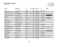
Figure 1<br />
Model JA Model JRA (For Low Centerline Applications)<br />
Figure 2<br />
Model JA HTD Model JRA HTD (For Low Centerline Applications)<br />
Table 2<br />
Standard Dimensions (inches)<br />
Model A A(R) B B(R) C D E E(R) F STD MIN MAX H J W<br />
7 1 / 4<br />
7 1 / 4<br />
7 1 / 4<br />
8 1 27<br />
/4<br />
1 / 2<br />
301 5<br />
5<br />
5<br />
/ 4<br />
5 1 12<br />
/8<br />
1 / 2<br />
12 1 / 2<br />
12 1 4<br />
/ 2<br />
14<br />
5 / 8<br />
4 5 / 8<br />
4 5 / 8<br />
5 1 8<br />
/4<br />
1 / 4 11 1 / 4<br />
11 1 / 4<br />
11 1 / 4<br />
11 1 14 3<br />
14 3<br />
14 3<br />
/ 4 14 3 3 8<br />
/ 4<br />
1 / 2<br />
81 / 2<br />
81 / 2<br />
101 6<br />
/ 4<br />
1 / 8<br />
6 1 / 8<br />
6 1 / 8<br />
8 1 11<br />
/ 8<br />
1 / 2<br />
11 1 / 2<br />
11 1 / 2<br />
13 5 J15A-10<br />
24<br />
J30A-10<br />
J30A-12<br />
J50A-15<br />
/ 8<br />
1 / 4<br />
24 1 / 4<br />
24 1 / 4<br />
27 3 3<br />
/4<br />
1 / 2<br />
3 1 / 2<br />
3 1 / 2<br />
4 3 27<br />
/8<br />
1 / 2<br />
27 1 8<br />
/ 2<br />
1 / 4<br />
81 / 4<br />
81 -<br />
-<br />
-<br />
/ 2<br />
-<br />
J15A-10HTD<br />
7<br />
J30A-10HTD<br />
J30A-12HTD<br />
J50A-15BHTD<br />
*Consult Factory<br />
1 / 4<br />
7 1 / 4<br />
7 1 / 4<br />
8 1 29<br />
/4<br />
3 / 4<br />
29 3 / 4<br />
29 3 / 4<br />
34 1 28<br />
/ 4<br />
3 / 4<br />
28 3 / 4<br />
28 3 / 4<br />
32 1 3<br />
/4<br />
1 / 2<br />
3 1 / 2<br />
3 1 / 2<br />
4 3 5<br />
5<br />
5<br />
/8 5 1 12<br />
/8<br />
1 / 2<br />
12 1 / 2<br />
12 1 5<br />
/ 2<br />
14<br />
5 / 8<br />
5 5 / 8<br />
5 5 / 8<br />
6 1 7<br />
/4<br />
3 / 8<br />
7 3 / 8<br />
7 3 / 8<br />
8 1 11<br />
/ 2<br />
1 / 4<br />
11 1 / 4<br />
11 1 / 4<br />
11 1 10<br />
/ 4<br />
1 / 4<br />
11 3 / 4<br />
11 3 / 4<br />
11 3 4 3<br />
4 3<br />
4 3<br />
/ 4 4 33 * 9<br />
* 9<br />
* 9<br />
/4 * 10 3 16<br />
16<br />
16<br />
/ 8 18 1 J50A-15HTD 8<br />
/8<br />
1 34 /4<br />
1 / 4 32 1 /4 4 3 /8 5 1 /8 14 6 1 /4 8 1 / 2 11 1 / 4 11 3 / 4 4 33 /4 * 10 3 / 8 18 1 8<br />
/8<br />
1 30 /4<br />
1 / 4 5 1 /8 14 5 1 /4 11 1 / 4 14 3 3 / 4 101 / 4 8 1 / 8 13 5 J50A-15B 27 / 8<br />
3 /4 4 3 /8 81 / 2 -<br />
3. ACCEPTANCE PROCEDURE<br />
Uncrate burner carefully and check all parts received against your computer generated Bill of Material.<br />
Warranty<br />
The Owners Information envelope packed with the burner contains a Warranty Registration Card. The Warranty<br />
Registration Card is also a request form for a Spare Parts List. An on-hand supply of spare parts is highly recommended<br />
in case of emergency shutdown. We request that you complete and return the card to <strong>Power</strong> <strong>Flame</strong> in<br />
the enclosed self-addressed envelope as soon as possible.<br />
4. INSTALLATION<br />
Before Beginning Installation, Carefully Study These Instructions, All Charts,<br />
Drawings And Diagrams Shipped With The Burner.<br />
Installation must be in accordance with all local and national codes including CAN1-B149.1 or B149.2 and<br />
Canadian electrical codes for Canadian installations.<br />
G<br />
Note:<br />
Add 3/8” to”H” for size of<br />
opening in heat exchanger<br />
front plate.<br />
Note:<br />
Add 3/8” to”H” for size of<br />
opening in heat exchanger<br />
front plate.
4.1<br />
4.2<br />
If the burner is to be mounted in an existing boiler or furnace, be sure that all fire-side surfaces are clean and in<br />
good condition. All doors, cleanouts, cracks or other openings allowing excess air into the combustion<br />
chamber should be tightly sealed, whether the burner is to be fired under positive or negative Combustion<br />
Chamber Conditions.<br />
The burner can be mounted through a fire door (Figure 3), in the base of the boiler (Figure 4)or through a heat<br />
exchanger side/end wall (Figure 6). When mounting through the fire door it may be necessary to install the<br />
burner at a downward angle to avoid impingement on the crown sheet. For fire door installations, complete<br />
the boiler base construction as shown in Figure 3.<br />
JAHTD Installation (Figure 5)<br />
The standard adiabatic chamber length is 8”. If the burner blast tube insertion depth (Dimension “G”), i.e., the<br />
burner flange setting depth, is more than 4”, the adiabatic chamber must be lengthened proportionately.<br />
Example: If the blast tube flange setting is 6”, the adiabatic chamber needs to be ordered with a 10” length.<br />
Figure 3 Mounting in Fire Door<br />
Figure 4 Mounting in Base of <strong>Boiler</strong><br />
Figure 5 JA HTD Mounting with Adiabatic Chamber<br />
See<br />
Detail A<br />
Refractory Material<br />
(By Installer)<br />
Flange Gasket<br />
Burner Flange<br />
Burner Blast Tube<br />
Flange Gasket<br />
Adiabatic Chamber Flange<br />
Burner Flange<br />
Gasket or Rope<br />
(By Installer)<br />
Adiabatic Chamber<br />
Detail A<br />
Burner Blast Tube<br />
Adiabatic Chamber<br />
See Detail A<br />
Flange Gasket<br />
Burner Flange<br />
Burner Blast Tube<br />
Adiabatic Chamber<br />
* On applications that<br />
require heat exchanger<br />
front plate transmission<br />
protection (such as boiler<br />
and hot oil heaters) the<br />
insulating and/or refractory<br />
material is to be installed by<br />
the contractor in accordance<br />
with the heat<br />
exchanger manufacturers<br />
recommendations. At the<br />
installers option the entire<br />
length of the adiabatic<br />
chamber may be surrounded<br />
with the insulating<br />
material chosen.<br />
JA3<br />
Rev.0203
JA4<br />
Rev.0203<br />
4.3<br />
4.4<br />
4.5<br />
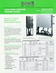
Figure 6 Mounting in Heat Exchanger<br />
Table 4<br />
Gas Piping Pressure Drop Data<br />
Minimize blast tube extending into<br />
combustion chamber or protect<br />
tube with insulated sleeve.<br />
EQUIVALENT LENGTHS OF STRAIGHT PIPE IN FEET<br />
20 30 40 50 60 80 100 150 200<br />
Pipe Size In Inches CFH GAS WITH .2" PRESSURE DROP<br />
1" 300 250 210 190 180 150 135 110 75<br />
11/4" 520 425 360 325 300 260 230 190 165<br />
11/2" 800 690 560 500 480 410 370 300 260<br />
2" 1700 1400 1200 1100 1000 850 750 600 540<br />
21/2" 3000 2500 2100 1900 1800 1550 1375 1100 950<br />
EQUIVALENT LENGTH OF STANDARD PIPE IN FEET FOR LISTED FITTINGS<br />
Fitting Type 1” 1 1/ 4 ” 1 1/ 2 ” 2” 2 1/ 2 ” Nominal Pipe Size In Inches<br />
Std. Tee 5.5 7.5 9.0 12.0 13.5<br />
Std. Elbow 2.7 3.7 4.5 5.5 6.1<br />
Flange Gasket<br />
JRA or JD Burner<br />
COMBUSTION CHAMBER SIZING<br />
Table 3<br />
Combustion Chamber Recommended Dimensions<br />
GAS INPUT<br />
MBTU/HR<br />
WIDTH<br />
Inches<br />
LENGTH<br />
Inches<br />
GAS INPUT<br />
MBTU/HR<br />
WIDTH<br />
Inches<br />
LENGTH<br />
Inches<br />
250 13 17 1075 20 28<br />
450 15 20 1260 23 33<br />
600 16 23 1500 25 38<br />
700 17 25 1800 26 40<br />
850 18 26 2200 28 42<br />
2500 28 44<br />
Whatever the method of mounting chosen, the burner blast tube must be recessed into the front wall surface from<br />
0" to 1 1/2".<br />
Serious Damage To The Burner May Result If The Blast Tube Is Extended<br />
Into The Combustion Chamber.<br />
Secure the burner to the boiler, using the burner mounting flange. The burner mounting flange must be welded to<br />
the blast tube at the selected location for proper insertion. A tight seal between mounting flange and front plate<br />
should be accomplished using the optional flange gasket supplied by <strong>Power</strong> <strong>Flame</strong> Incorporated, a ceramic or<br />
other non-asbestos fiber rope.<br />
5. GAS PIPING<br />
5.1 Contact your local gas service company to ensure that adequate gas service is available and to review applicable<br />
installation codes for your area.<br />
5.2 Size the main gas line in accordance with Table 4. The figures shown are for straight lengths of pipe at 0.2 ins. w.c.<br />
pressure drop, which is considered normal for low pressure systems. Note that fittings such as elbows and tees will<br />
add to the pipe pressure drop.
5.3 Refer to Figure 7 for details of gas piping. (Also refer to any additions to piping diagrams supplied for this<br />
specific unit.)<br />
5.4 Mount leakage test and main gas cocks, main automatic gas valve or combination gas valve/pressure<br />
regulator, and (where required) auxiliary valves (if not factory mounted) and connect gas valve wires through<br />
flexible conduit to control terminal strip in accordance with wiring diagrams and all applicable codes.<br />
5.5 Install pressure regulator (not used with combination gas valve/pressure regulator) directly upstream of main<br />
automatic gas valve(s) and fit drip leg and main gas cock upstream of regulator or automatic valve(s).<br />
5.6 The pilot line should be piped into the upstream tapping on the main shut-off cock to gas train. An optional<br />
location is a tee piped in just upstream of main shut-off cock. Refer to Figure 7. For ease of servicing we<br />
recommend the use of a union immediately upstream of the main gas pressure regulator or combination gas<br />
valve/pressure regulator.<br />
Figure 7 UL Gas Piping Train for JA Burners<br />
5.7 Install vent lines from main gas regulator (if used) and (if applicable) diaphragm gas valve. Vent line should be<br />
run to the outside of the building, terminating clear of windows or fresh air intakes. Outside terminal of vent<br />
should have a screen to prevent insects from building nests in vent pipe. The vent should terminate in a manner<br />
which will preclude the possibility of water, dirt or other matter from entering the line.<br />
5.8 Test gas lines for leaks using soap solution. Your local gas service company may wish to carry out or witness<br />
this test. CAUTION - gas pressure above 14 ins. w.c. may damage the standard diaphragm gas shut-off valve.<br />
Do not exceed this value when pressure testing lines unless you cap off line upstream of main gas cock and<br />
pilot take-off.<br />
5.9 Check that side orifice size is correct according to burner specsheet. See Figure 8. To gain access to orifice,<br />
remove Plug A and withdraw spring and orifice. When replacing orifice, ensure that it seats properly inside the<br />
tee. The spring may be deformed slightly so as to hold the orifice firmly for insertion.<br />
Figure 8 Location of Side Orifice (When Supplied)<br />
Pressure<br />
Test Point<br />
Plug A<br />
Location of Side Orifice (When Supplied)<br />
Orifice Spring<br />
JA5<br />
Rev.0701
JA6<br />
Rev.0405<br />
6. WIRING<br />
6.1 Refer to wiring diagram shipped with burner.<br />
6.2 Electrical installation must be made in accordance with the National Electrical Code and applicable local<br />
codes. If this burner is part of a boiler or furnace package system - check wiring diagram as supplied by the<br />
boiler or furnace manufacturer.<br />
7. START UP<br />
Before attempting start up, thoroughly study and familiarize yourself with the exact sequence of operation and<br />
all other details on the specific <strong>Flame</strong> Safeguard Control System being used. This information will be found in<br />
bulletins supplied with the burner, as well as technical bulletins covering other components. All of these should<br />
be used as reference material in burner start up and service.<br />
7.1 Check boiler water level (if applicable).<br />
7.2 Lay out combustion testing equipment (See Section 8).<br />
7.3 Attach gas pressure gauge or manometer to upstream side of main gas cock (0-35 ins. w.c.) and to burner side<br />
orifice tee, (0-10 ins. w.c.) as well as to pilot gas pressure test tee tapping (0-10 ins. w.c.).<br />
7.4 Check the voltage at disconnect switch to make certain that it matches that shown on the burner label.<br />
7.5 Make certain that all dampers in flue or stack are in wide open position, or as appropriate for start up.<br />
7.6 Install stack thermometer and CO2 sample line to breeching and draft gauge to combustion chamber test point.<br />
7.7 Connect DC volt meter or microammeter to <strong>Flame</strong> Safeguard Control as appropriate to determine flame detection<br />
system signal values. Refer to Table 5.<br />
7.8 With the main and leak test cocks and pilot cocks in OFF position, turn on gas cock at meter. Check to make<br />
certain that pressure upstream of main and pilot cocks does not exceed 14 ins. w.c. ( 1 / 2 PSIG) - unless special<br />
valve train components suitably rated have been furnished (Refer to Burner Specsheet). If pressure is acceptable,<br />
proceed to next step.<br />
7.9 Next, check the operation of the gas pilot system. This is a very important part of the start up procedure.<br />
A. Remove the pilot assembly and check for proper orifice size and spark gap. The spark is to arc against the outside<br />
radius of the pilot assembly case (not the pilot head nozzle) on <strong>Flame</strong> Rod pilots only. See Figures 9 and 10.<br />
On UV pilots the spark is to arc against the pilot head. See Figure 11.<br />
B. <strong>Flame</strong> Safeguard Programming Controls supplied can be of several different models (with varying sequences),<br />
depending upon the code requirements. Before attempting burner start up make certain that you are familiar<br />
with the operation of the <strong>Flame</strong> Safeguard Control and other components being used on this specific application.<br />
This information will be found in bulletins printed by Honeywell or Fireye. A copy of this bulletin was supplied<br />
with the burner. See Figure 10 for settings using S8600 control.<br />
C. In order to prepare the pilot for proper operation, it is essential that appropriate adjustments be made to the<br />
burner air inlet damper and the pilot gas pressure. It is necessary that the air damper remain in one fixed position<br />
at least 1 /2" open on one damper until it is determined that the pilot test will ignite instantly and stabilize with<br />
a good flame signal. Typical pilot test tee pressures for all TYPE JA burners are 11/2" to 21/2" w.c. for natural gas<br />
and 1" to 2" for propane gas. Typically lower pressures are for air damper openings of 50% or less, and higher<br />
pressures for air damper light off openings greater than 50%. The HTD air damper arrangement is designed for<br />
operation with the pilot and full low fire operating positions, such that the air dampers will be fully (or nearly)<br />
closed. Pilot test tee pressures for the JA15, JA30, and JA50 HTD burners will vary from 1” to 2” w.c., the best<br />
job specific pressure to be determined by the technician performing the on site start up.<br />
D. Frequently the cause for pilot problems relates to gas pressures that are too high and/or air dampers that<br />
are closed too far. Both conditions can cause a fuel rich mixture in the pilot box which can substantially<br />
delay or totally prevent pilot ignition. Read the following start up procedure thoroughly before proceeding.<br />
E. Perform an initial Spark Pickup Test. With the pilot gas cock closed, the burner will go through a blower prepurge<br />
period, after which the gas pilot ignition transformer will be energized, although no pilot will be established.<br />
(At no time should there be any flame signal reading, nor should the main gas valve attempt to open.) At the<br />
end of the pilot trial for ignition and blower purge period, the flame safeguard control should shut the system<br />
down in a safety lock-out mode, requiring manual reset of the flame safeguard control to restart burner. If a flame<br />
signal is detected, verify the flame retention tab and ignition electrode are properly positioned, per Figure 11.
Figure 9 Pilot Assembly - <strong>Flame</strong> Rod Type - Natural Gas Only (Do Not Use with Propane Gas)<br />
Figure 10 Pilot Assembly using S8600 or S8680J Control<br />
Figure 11 Pilot Assembly - Scanner Type - Natural or LP Gas<br />
*See alternate setting<br />
Figure 10 drawing when<br />
using S8600 Control<br />
Note: Pilot <strong>Flame</strong> current<br />
should be at least two<br />
microamps and steady.<br />
JA7<br />
Rev.0405
JA8<br />
Rev.0405<br />
Figure 12 Typical Circuit Board Layout Drawing<br />
Figure 13 Typical Electrical Schematic with Light & Switch Circuit Board<br />
* Main 115 volt hot incoming power terminal is<br />
located at the top of the circuit board. Neutral 115<br />
volt power terminal is located on the lower set of<br />
terminals at the bottom of the main circuit board.
Figure 12 & Figure 13 Parts List<br />
1 Terminal Strip for Field Connection<br />
2 Grounding Lug<br />
3 Replaceable Fuse<br />
4 Hot Main <strong>Power</strong> Connection*<br />
5 Light & Switch Board Connection<br />
6 <strong>Flame</strong> Safeguard<br />
7 Replaceable Relays<br />
8 Neutral<br />
9 Auxiliary <strong>Power</strong> Connection<br />
10 Running Interlock Connections<br />
11 Limit Device Connections (Typical)<br />
12 Main Circuit Board<br />
Pilot Positioning Safety Stop<br />
Figure 14 Pilot Positioning Safety Stop<br />
13 (L2) Neutral 115 Volt Wiring<br />
Connection*<br />
14 (L1 Main) Hot 115 Volt <strong>Power</strong><br />
Connection*<br />
15 Control Circuit Fuse<br />
16 Operating Valve Connections<br />
17 Gas Ignition Transformer<br />
18 Modulation Motor Connections<br />
19 <strong>Flame</strong> Detector Connection<br />
20 Operating Control Connection<br />
21 Wiring Terminal Strip Identification<br />
22 Burner Motor<br />
<strong>Power</strong> <strong>Flame</strong> P/N X09668 retaining ring is assembled to the pilot assembly at the factory, and is not to be<br />
removed or repositioned at any time during the intial commissioning of the burner or during subsequent burner or<br />
pilot maintenance activities. Replacement pilots will also have this clip prepositioned and under no circumstances<br />
should it be moved from the factory set position, or tampered with in any manner.<br />
This stop prevents the pilot from being retracted to a position which may cause pilot-to-main flame transition<br />
problems, while allowing sufficient room for minor pilot position adjustment.<br />
7.10 With the Main and Leak gas cocks Closed-Pilot gas cock Open: Turn the burner switch ON. The blower motor will<br />
purge the heat exchanger of any accumulated combustibles. At the end of the purge cycle, which may be as<br />
short as 30 seconds for fixed air dampers or as long as 90 seconds with automatic air dampers, the pilot solenoid<br />
valve and ignition transformer will energize.<br />
7.11 Pilot Adjustment and Main <strong>Flame</strong> Light Off Procedure for Burners with Fixed Air Dampers<br />
A. Set the air flow and pilot gas pressure in order to provide instant pilot ignition, good flame stability and flame signal<br />
readings. This can be accomplished as follows: Observe pilot signal with DC Voltmeter or Microammeter (as appro-<br />
JA9<br />
Rev.0405
JA10<br />
Rev.0405<br />
priate) and reduce pilot gas pressure to a point where the signal is erratic or reduced substantially from initial<br />
reading (See Table 5 for flame signal values).<br />
B. Raise the pilot gas pressure to the point where the signal is again stable. Remove scanner (if used in this application)<br />
and use a mirror to view the pilot flame through the scanner pipe (you may need a live flame from a cigarette lighter<br />
or butane torch to keep scanner actuated). Be sure that you are getting full coverage of scanner pipe by pilot flame.<br />
If flame rod is used, make certain of its correct positioning in pilot assembly. If pilot is slow in lighting, this may be<br />
due to air in the pilot line. Eliminate air and/or adjust pilot gas pressure regulator flow rate.<br />
C. After attaining the proper pilot flame signal values, cycle the pilot off and on several times in order to ensure<br />
reliability (with the main and gas leak test cocks still closed). Turn Burner Switch Off.<br />
D. Having established pilot reliability, open gas leak test cock (with main gas cock still closed) and start burner.<br />
E. After burner has pre-purged and established good pilot flame signal readings, the main automatic fuel valve will<br />
be energized. As this valve begins to open, slowly open the main gas cock to light off the main flame. The main<br />
flame should light immediately. If not, it is possible that you will have to eliminate air from the main gas line, adjust<br />
main gas pressure regulator flow rate and/or adjust bleed valve at vent line connection on main diaphragm<br />
type automatic gas valve when furnished.<br />
F. Adjust burner as necessary to provide smooth ignition of main flame. If pilot flame signal drops significantly when<br />
main fuel valve opens, slightly increase pilot gas pressure to attain reasonably stable flame signal value.<br />
G. Make certain that the air flow setting provides correct CO2, O2 and other combustion values at the proper firing<br />
input rates. (See Section 8 and Table 6 for firing rate information). Generally accepted values for natural gas are<br />
8 1/2 to 10% CO2 (carbon dioxide) and little or no* CO (carbon monoxide). Equivalent CO2 ratings on propane gas<br />
are 10 to 11 1/2%. Check also with local utility and any other authorities having jurisdiction before making final<br />
burner adjustments.<br />
7.12 Pilot Adjustment and Main <strong>Flame</strong> Light Off Procedure for Burners with Automatic Dampers<br />
A. If the burner has automatic air dampers (operated by linkage from the main automatic fuel valve, or by a 2 position<br />
or modulating firing rate motor) ensure that the air dampers are held (fixed) in the pilot lighting (low) air flow position<br />
(See Page JA6, 7.9, Item C) until all pilot adjustments are completed.<br />
B. Depending upon the flame safeguard programmer being used, it may be necessary to temporarily disconnect<br />
the wires powering the main automatic fuel valve and/or employ the use of the check/run switch in the <strong>Flame</strong><br />
Safeguard Programming Control to hold the timing function at the pilot iginition position while making pilot<br />
adjustments.<br />
Table 5 Acceptable Pilot and/or Main <strong>Flame</strong> Current Readings<br />
Control<br />
R7795A or C<br />
R7795B or D<br />
R4795A (D)<br />
R4140M (G,L) or<br />
BC7000<br />
RM7800<br />
S8600<br />
TFM-2(3) or MII<br />
UVM-2(3)(5) or MII<br />
D Series<br />
E110<br />
* Note: Although Underwriters Laboratories permits higher readings of CO (carbon monoxide), it is desirable to obtain readings between 0 and 100 ppm, depending on<br />
Photocell of <strong>Flame</strong> Rod<br />
N/A<br />
2 Microamps<br />
2 Microamps<br />
2-5 Microamps<br />
1.25-5.0 DC Volts<br />
1-5 Microamps<br />
14-17 DC Volts1 N/A<br />
15-25 DC Volts<br />
10 min., 20 or greater normal<br />
1. 4-10 Microamps - with Microammeter in series with S-2 Wire to <strong>Flame</strong> Rod<br />
U.V.<br />
3 1 /2 Microamps<br />
N/A<br />
1 1 /2 Microamps<br />
3 1 /2 -7 1 /2 Microamps<br />
1.25-5.0 DC Volts<br />
N/A<br />
N/A<br />
5-6 DC Volts<br />
15-25 DC Volts<br />
10 min., 20 or greater normal<br />
Lead Sulfide<br />
N/A<br />
N/A<br />
N/A<br />
2-5 Microamps R7248A Red Amp<br />
3 1 /2 Microamps R7248B Red Amp<br />
N/A<br />
N/A<br />
N/A<br />
N/A<br />
15-25 DC Volts<br />
N/A<br />
C. Set the air flow and pilot gas pressure such as to provide instant ignition, good flame stability and flame signal<br />
readings. This can be accomplished as follows:<br />
D. Observe pilot signal with DC Voltmeter or Microammeter (as appropriate) and reduce pilot gas pressure to a point<br />
where the signal is erratic or reduced substantially from initial readings. (See Table 5 for flame signal values). Raise<br />
the pilot gas pressure to the point where the signal is again stable. Remove scanner (if used in this application)<br />
and use a mirror to view the pilot flame through the scanner pipe (you may need a live flame from a cigarette lighter<br />
or butane torch to keep scanner actuated). Be sure that you are getting full coverage of scanner pipe by pilot flame.<br />
If flame rod is used, make certain of its correct positioning in pilot assembly. If pilot is slow in lighting, it may be<br />
due to air in the pilot line. Eliminate air and/or adjust pilot gas pressure regulator flow rate.<br />
local codes and heat exchanger manufacturer’s recommendations.
E. After attaining the proper pilot flame signal values, cycle the pilot off and on several times in order to ensure its<br />
reliability (with the main and leak gas cocks still closed). Turn the Burner Switch Off.<br />
JA11<br />
Rev.0405<br />
F. Electrically reconnect main automatic fuel valve. Make certain that linkage (when used) from the automatic fuel valve<br />
to the air damper is in place. Air damper opening should be set to pilot air flow ignition position. If necessary, return<br />
flame safeguard check/run switch to the automatic position.<br />
G. Open gas leak test cock (with main cock still closed) and start burner.<br />
H. After burner has pre-purged and established good pilot flame signal readings the main automatic fuel valve will be<br />
energized. As this valve begins to open, slowly open the main gas cock to light off the main flame. The main flame<br />
should light immediately. If not, it is possible that you will have to eliminate air from the main gas line and/or adjust<br />
main gas pressure regulator flow rates.<br />
I. Adjust burner as necessary to provide smooth ignition of main flame. If flame signal drops significantly when main<br />
automatic gas valve opens, slightly increase pilot gas pressure to attain stable flame signal value.<br />
J. For Low/High/Off burners - adjust the main gas pressure regulator in combination with the air damper linkage operation<br />
to achieve 81/2 to 10% CO2 (carbon dioxide) and little or no* CO (carbon monoxide) at the full high fire input<br />
rate position. Make certain the linkage operates smoothly and without binding or overtravel of the air damper stops.<br />
K. For Low/High/Low burners - adjust the main gas pressure regulator in combination with the air damper linkage<br />
operation to achieve 81/2 to 10% CO2 (carbon dioxide) and little or no* CO (carbon monoxide) at the full high fire<br />
input rate position. Make certain the linkage operates smoothly and without binding or overtravel of the air damper<br />
stops. Run burner to the low fire position and lock motorized gas valve internal low fire adjustment to a setting that<br />
will attain 7 to 9% CO2 at the desired low fire input rate.<br />
L. Intermittently operate the burner until the water is warm in the boiler, follow specific initial firing recommendations<br />
provided by the heat exchanger manufacturer.<br />
Burners Designed for Full Modulation Operation<br />
After completing pilot adjustments and other procedures as appropriate in items A through I above, proceed with<br />
modulating adjustments as follows:<br />
M. Initial adjustments should be made at the low fire position. All <strong>Power</strong> <strong>Flame</strong> burners are factory tested and adjusted.<br />
However, to determine that the metering butterfly valve is, in fact, in the low fire position, observe the end of the<br />
metering valve shaft. The slot in the end of the shaft indicates the position of the valve. When the slot is in the<br />
horizontal position (parallel with the gas flow direction), the valve is fully open.<br />
N. Turn the burner on and let it advance to the main flame light off position. Take action as necessary to hold the linkage<br />
at the low fire position by using a manual potentiometer or electrically disconnecting the modulating motor. <strong>Power</strong><br />
<strong>Flame</strong> burners are tested at the factory and linkage adjustments for modulation are made at that time. Note that the<br />
factory settings relate to good operation while firing into open test pits, and therefore will normally not relate directly<br />
to absolute fuel/air ratios while firing under specific field conditions. It is suggested that the factory settings be noted<br />
and marked on the linkage prior to proceeding with the final adjustment. In this manner those settings can be<br />
restored as initial reference points, if need be.<br />
O. With the burner in the factory set low fire position, adjust air and fuel linkage to good fuel/air ratio settings (7 to 9% CO2,<br />
little or no* CO). Mark the linkage at the new settings.<br />
P. Increase the firing rate to the midway point. Set the fuel/air ratios to achieve good combustion values (7 to 9% CO2 ,<br />
little or no* CO). Mark the linkage as a reference point for this new mid fire position.<br />
Q. Increase the rate to high fire position and repeat the test done for the midpoint adjustment. Results should range in<br />
the area of 81/2 to 10% CO2, with little or no* CO. The metering device setting and air damper openings should be<br />
marked and noted to obtain high fire reference points. Note that an additional point of the fire adjustment may be<br />
obtained by modifying the regulated gas pressure delivered to the burner metering device. The burner pressure regulator<br />
is used to obtain this adjustment and can be used within available pressure limits to obtain optimum firing conditions.<br />
R. Operate the modulating lever arm on the modulating motor through the three previously referenced points. Minor<br />
settings modifications may be required to ensure that the reference points are acquired.<br />
S. Tighten (finger tight) the hex bolt to the linkage rod at the swivel on the modulating motor driver arms and run<br />
the motor through its full travel to ensure that the linkage is free and that limits on the metering device and air<br />
dampers are not exceeded.<br />
* Note: Although Underwriters Laboratories permits higher readings of CO (carbon monoxide), it is desirable to obtain readings between 0 and 100 ppm, depending on<br />
local codes and heat exchanger manufacturer’s recommendations.
JA12<br />
Rev.0405<br />
T. Determine that the required gas input rate is being achieved by clocking the gas flow at the gas meter. Consult<br />
the gas utility to determine if any correction factors have to be applied to the indicated meter flow rates.<br />
U. Intermittently operate the burner until the water is warm in the boiler, or follow specific intial firing recommendations<br />
provided by the heat exchanger manufacturer.<br />
V. Tighten all linkages and permanently mark settings.<br />
7.13 Conduct all applicable test procedures shown in control manufacturer's bulletins included with burners. Set and<br />
check operation of low and high gas pressure switches (if applicable), all burner and heat exchanger controls,<br />
and operating devices. Check blower air flow switch by first closing main gas cock and disconnecting motor<br />
lead wire. Also, perform a final Spark Pickup Test following the procedures outlined in 7.9E.<br />
7.14 Gas Pilot Flood Test<br />
Many pilot problems are caused by a poor mixture of gas and air at the point of ignition (ignition spark gap). The<br />
cause of this poor mixture condition is usually excessive gas flow or insufficient air (air dampers are closed too far).<br />
Once the pilot is adjusted and felt to be correct, it is suggested that the following test be conducted to further<br />
verify that the pilot will be reliable.<br />
A. Turn the burner off and shut the manual leak test cock in the main gas train. (This valve should always be closed<br />
when making pilot adjustments.)<br />
B. If the burner is Low/High/Off, Low/High/Low or Modulating, take steps to keep the fuel air linkage in the pilot off<br />
position. If the flame safeguard control has a timer check switch, it can be placed in the test position. If the flame<br />
safeguard control does not have the timer switch, it may be necessary to disconnect the power wire to the motorized<br />
gas valve.<br />
C. Install a 0 to 10” w.c. gas pressure gauge or a manometer in the pilot test tee fitting. Plug an appropriate flame<br />
signal meter into the flame safeguard control.<br />
D. Disconnect the high tension ignition leadwire at the ignition transformer secondary terminal. Either hold onto the<br />
insulated portion or let the free ignition wire hang loose, so that it is not able to come into contact with the bare<br />
ignition terminal on the transformer.<br />
E. Start the burner and let it go through the prepurge period. As soon as the pilot ignition circuit is energized (listen<br />
for the sound of the solenoid valve opening or watch the pilot gas pressure gauge), let about 3 to 4 seconds<br />
lapse and then CAREFULLY (the ignition transformer produces 6000 volts) touch the ignition leadwire to the transformer<br />
terminal secondary.<br />
If the pilot fuel/air mixture and ignition electrode are adjusted correctly, the pilot will light instantly and the flame<br />
signal reading will be steady and of the correct value. If the pilot does not light instantly, then readjust the pilot<br />
gas pressure and/or the air dampers and/or the ignition electrode setting according to the information provided<br />
in this manual.<br />
F. Turn the burner off. Reconnect the ignition leadwire to the ignition transformer secondary terminal. Set the check<br />
switch in the flame safeguard control for automatic operation. Reconnect any wires that have been disconnected<br />
to hold the motorized gas valve in the pilot position. Open the checking gas cock, turn the burner on and verify<br />
that the pilot lights and proves instantly, providing good, smooth ignition of the main gas flame.<br />
G. If the Gas Pilot Flood Test is successful, it is not always a guarantee of correct pilot air/fuel mixture, but a failure<br />
will almost always indicate an excessively rich mixture.<br />
7.15 Clean up the area around the burner and instruct owner and/or operator.<br />
7.16 Post Operating Instructions card (inside back cover) close to the burner in clearly visible position.<br />
8. COMBUSTION ARRANGEMENT REQUIREMENTS<br />
8.1 The JA burner has been designed to fire with high combustion efficiency into combustion chambers with positive,<br />
balanced or negative pressures.<br />
8.2 In order to fire efficiently, the burner requires an adequate supply of combustion air. Ventilation to the boiler room<br />
should be provided on the basis of 1/2 square inch of opening for each 1000 BTU/HR input. This excludes the<br />
requirements for any other fired equipment in the room. The boiler room should not become excessively hot and<br />
under no circumstances should it be under a negative pressure.<br />
8.3 The burner should be set up initially and serviced at regular intervals (suggested beginning of and midwinter) by<br />
a trained serviceman using the proper test instruments. Failure to maintain the correct burner settings may result<br />
in inefficient gas consumption, premature wear of burner components, or explosion hazard.
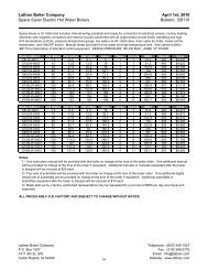
Table 6<br />
Propane Gas/Natural Gas Orifice Pressure Settings/Flow Rate with V4943B Combination Valve<br />
Natural or MBH Burner Natural Gas Propane Gas<br />
LP Gas Model 1000 BTU/cf .64 S.G. 2550 BTU/cf 1.55 S.G.<br />
SIDE PRESSURE PRESSURE * GAS SIDE SIDE PRESSURE PRESSURE<br />
ORIFICE INTO INTO MAIN TRAIN ORIFICE ORIFICE INTO MAIN INTO<br />
Input MBH DRILL ORIFICE TEE S/O COCK SIZE DECIMAL DRILL GAS SHUT OFF ORIFICE TEE<br />
SIZE MIN. DIAMETER SIZE COCK<br />
INCHES W.C. INCHES W.C. INCHES INCHES W.C. INCHES W.C.<br />
300 J15A-10 5/16 3.75 3.7 1" .187 3/16 4.0 3.3<br />
350 J15A-10 11/32 3.3 3.7 1" .281 9/32 4.0 3.1<br />
400 J15A-10 3/8 3.1 3.6 1" .297 19/64 4.0 3.4<br />
475 J15A-10 13/32 3.3 3.9 1" .328 21/64 4.0 3.1<br />
500 J15A-10 27/64 3.2 3.9 1" .328 21/64 4.0 3.5<br />
550 J15A-10 7/16 3.5 4.2 1" .359 23/64 4.0 3.3<br />
600 J15A-10 15/32 3.3 4.1 1" .390 25/64 4.0 3.4<br />
650 J15A-10 1/2 3.1 4.1 1" .406 13/32 4.0 3.0<br />
700 J15A-10 17/32 3.1 4.2 1" .406 13/32 4.0 3.5<br />
800 J30A-10(12) 9/16 3.3 4.8 1"(1-1/4") .422 27/64 4.0 3.8<br />
900 J30A-10(12) 11/16 2.7 4.5 1"(1-1/4") .437 7/16 4.5 4.1<br />
1000 J30A-10(12) 3/4 2.9 5.1 1"(1-1/4") .500 1/2 4.5 3.7<br />
1100 J30A-12 3/4 3.6 4.6 1-1/4" .562 9/16 4.5 3.4<br />
1200 J30A-12 None 2.7 4.0 1-1/4" .625 5/8 4.5 3.1<br />
1260 J30A-12 None 3.0 4.4 1-1/4" .625 5/8 4.5 3.4<br />
1260 J50A-15 11/16 3.6 4.3 1-1/2" .562 9/16 4.5 3.1<br />
1400 J50A-15 3/4 3.5 4.4 1-1/2" .594 19/32 4.5 3.2<br />
1600 J50A-15 7/8 3.3 4.4 1-1/2" .625 5/8 4.5 3.0<br />
1800 J50A-15 1 3.4 4.7 1-1/2" .688 11/16 5.0 3.0<br />
2000 J50A-15 None 2.9 4.5 1-1/2" .719 23/32 5.0 3.1<br />
2200 J50A-15 None 3.5 5.4 1-1/2" .781 25/32 5.0 3.1<br />
2500 J50A-15B None 4.5 6.0 2" .938 15/16 6.0 2.8<br />
The above data is approximate for combustion chamber pressure of 0.0"<br />
w.c.; for application specific data, refer to the specification sheet provided<br />
with the burner. Use combustion readings (CO 2 or O 2, CO and stack temperatures)<br />
and flow meter to determine exact inputs.<br />
8.4 The correct test instruments are —<br />
A. CO 2 indicator (Fyrite or similar) or 0 2 analyzer<br />
B. CO indicator (Monoxor or similar)<br />
C. Stack thermometer<br />
D. Draft gauge or inclined manometer<br />
E. U-tube manometer or calibrated 0-10” and 0-35” w.c. pressure gauge<br />
F. Combination volt/ammeter<br />
G. DC Micro-Ammeter or DC Volt Meter as required by <strong>Flame</strong> Safeguard Programmer Selection<br />
8.5 Approximate gas flows and pressures are shown in Table 6 for natural gas and LP gas.<br />
9. SERVICE SUGGESTIONS<br />
* Increase pressures when using separate gas pressure regulator or<br />
auxiliary gas valve. When supply pressure is lower than that required<br />
for above data, the orifice size may be increased or removed to utilize<br />
the lower pressure. Consult factory for details.<br />
9.1 Burner Fails To Start<br />
1. Bad fuse or switch open on in-coming power source, or motor overload out.<br />
2. Control circuit has an open control such as operating, limit or low water cut-off.<br />
3. Reset button on motor or flame safeguard programming control open. Push reset button.<br />
4. Loose or faulty wiring. Tighten all terminal screws. Check wiring against wiring diagram furnished with burner.<br />
9.2 Burner Motor Runs, But Pilot Does Not Light<br />
1. Be sure gas is turned on at meter and pilot cock is open.<br />
2. Place hand on pilot valve to feel it open. Check gauge at tee in pilot line for gas pressure and prompt opening<br />
of pilot valve.<br />
JA13<br />
Rev.0405
JA14<br />
Rev.0405<br />
3. Check visually or by sound for spark arcing.<br />
4. Refer to section 7.9 on pilot checking procedures.<br />
5. Check air switch and be sure its circuit closes during start. Be sure timing card is inserted into <strong>Flame</strong> Safeguard.<br />
9.3 Burner Motor Runs, Pilot Lights But Main Gas Valve Does Not Open<br />
1. Check flame signal. If low, adjust pilot gas pressure and air settings for improved readings.<br />
2. Check gas valve circuit, both main valve and proof of closure switch (if so equipped).<br />
3. Main valve opening too slow - adjust bleed on diaphragm valve.<br />
4. Shut-off cock or test cock not open.<br />
5. Defective main valve.<br />
9.4 Occasional Lockouts For No Apparent Reason<br />
1. Re-check microamp or DC voltage readings. If insufficient, check gas pressure and air damper setting.<br />
Check electrodes setting. If flame rod pilot, flame rod may have to be re-positioned.<br />
2. Check ignition cable and electrode porcelain for damage or breaks which could cause short.<br />
3. Check for loose or broken wires.<br />
9.5 Burner Will Not Start - Even Though Burner Had Never Failed Before Or Had Been Running On Normal<br />
Cycling Without Failure<br />
1. Operating Control circuit open.<br />
2. Starting interlock such as proven low fire switch or proof of closure switch open.<br />
3. Defective control or loose wiring.<br />
4. Limit circuit open.<br />
An additional source of information relative to trouble-shooting can be found in the <strong>Flame</strong> Safeguard<br />
Programmer <strong>Manual</strong> supplied with the burner.<br />
10. COMPONENT ARRANGEMENT<br />
Figure 15 Type JA Basic Component Identification<br />
Type JA Front<br />
Firing Head<br />
Main Gas Inlet<br />
Ignition Transformer Blower Motor (Not Shown)<br />
Blast Tube<br />
<strong>Flame</strong> Safeguard<br />
Programmer<br />
Air Inlet Dampers<br />
Pilot Solenoid Gas Valve<br />
Air Flow Switch<br />
Pilot Gas Pressure<br />
Test Plug<br />
Reset Switch<br />
U.V. <strong>Flame</strong> Detector<br />
(or <strong>Flame</strong> Rod<br />
Lead Wire)<br />
Alpha ® System<br />
Circuit Board<br />
Customer<br />
Selectable Light<br />
<strong>Flame</strong> Failure<br />
Light<br />
On-Off Switch<br />
Demand Light<br />
Main Fuel Light<br />
<strong>Power</strong> On Light<br />
<strong>Flame</strong> Sight Port<br />
DIN Rail Mounted<br />
Terminal Strip<br />
Pilot Gas Pressure Regulator
Figure 16 Type JRA Basic Component Identification<br />
Type JRA Front<br />
Firing Head<br />
Ignition Transformer<br />
Figure 17 JA Burner Parts<br />
U.V. Detector<br />
Blower Motor<br />
Burners sold after 5/11/81<br />
will not have replaceable<br />
end rings.<br />
(5) No.6 Stainless Steel Ext. Tooth Lock Washer<br />
(5) 6-32 x 3/4 Stainless Steel Screws<br />
Q7800C Circuit Board Detail<br />
Air Flow Switch<br />
Pilot Solenoid<br />
Gas Valve<br />
Pilot Gas Pressure Regulator<br />
Pilot Gas Pressure Test Plug<br />
Air Inlet Dampers<br />
Air Housing Side - Damper<br />
Reset Switch<br />
Damper Assembly/Air Housing<br />
Mounting Gasket<br />
Damper Assembly<br />
Blast Tube<br />
<strong>Flame</strong><br />
Safeguard<br />
Programmer<br />
Main Gas Inlet<br />
JA15<br />
Rev.0405<br />
Note: For units built after 6/7/97, the<br />
number of screws and washers is 10<br />
for the J15/30A and 12 for J50A.<br />
(6) 1/4-20 Hex Head Cap Screw<br />
(6) 1/4” Lock Washer<br />
Air Inlet Cone With Screen
JA16<br />
Rev.0405<br />
Figure 18 JRA Burner Parts<br />
1 /4-20 Hex Head Cap Screw<br />
1 /4” Lock Washer<br />
Air Inlet Cone<br />
With Screen<br />
Air Housing<br />
Side - Damper<br />
Damper<br />
Assembly/Air Housing<br />
Mounting Gasket<br />
Damper Assembly<br />
Figure 19 JA HTD Burner Parts<br />
Burners sold after 5/11/81<br />
will not have replaceable<br />
end rings.<br />
(5) No.6 Stainless Steel Ext. Tooth Lock Washer<br />
(5) 6-32 x 3/4 Stainless Steel Screws<br />
Q7800C Circuit Board Detail<br />
(5) 6-32 x 3 /4 Stainless Steel Screws<br />
(5) No. 6 Stainless Steel Ext. Tooth Lock Washers<br />
J15/30A - 10 each; J50A - 12 each<br />
Air Housing Side - Damper<br />
Damper Assembly/Air Housing<br />
Mounting Gasket<br />
Damper Assembly<br />
Burners sold after 5/11/81 do not<br />
have replaceable end rings<br />
5 /16 -18 x 3 /4 Hex Head<br />
Note: For units built prior to 6/7/97, the<br />
number of screws and washers is 5.<br />
Note: For units built after 6/7/97, the<br />
number of screws and washers is 10<br />
for the J15/30A and 12 for J50A.<br />
(6) 1/4-20 Hex Head Cap Screw<br />
(6) 1/4” Lock Washer<br />
Air Inlet Cone With Screen
Figure 20 JRA HTD Burner Parts<br />
1 /4-20 Hex Head Cap Screw<br />
1 /4” Lock Washer<br />
Air Inlet Cone<br />
With Screen<br />
Air Housing<br />
Side - Damper<br />
Damper<br />
Assembly/Air Housing<br />
Mounting Gasket<br />
Damper Assembly<br />
JA/JRA/JA HTD/JRA HTD Burner Parts List<br />
1 Blower Housing/Cabinet/<br />
Damper Assembly<br />
2 Hood Assembly<br />
3 Blast Tube Assembly<br />
4 Diffusers (Includes Stainless Steel<br />
Mounting Screws)<br />
5 End Ring For Burners<br />
Sold Before 5/11/81 Only<br />
6 Mounting Flange<br />
7 Blower Wheel<br />
8 Motor Plate<br />
9 Blower Motors 3450 RPM<br />
10 Air Switch<br />
11 Ignition Transformer<br />
12 Sub-Base<br />
13 <strong>Flame</strong> Safeguard Control<br />
14 Timing Card for<br />
Programmer Timing Modules<br />
15 Amplifier<br />
16 Scanner<br />
17 Signal Light<br />
18 Side Orifice Tee<br />
19 Side Orifice Spring<br />
20 Pilot Valve<br />
21 Pilot Regulator<br />
22 Control Switch<br />
23 Terminal Strip<br />
24 Grounding Bar<br />
25 ITT Diaphragm Gas Valve<br />
25 Honeywell Diaphragm Gas Valve<br />
25.1 Auxiliary Solenoid Gas Valve<br />
(Not Shown)<br />
25.2 ITT Gas Valve Operator<br />
(Not Shown)<br />
25.2 Honeywell Gas Valve Operator<br />
25.3 ITT Gas Valve Body<br />
25.3 Honeywell Gas Valve Body<br />
(Not Shown)<br />
26 Side Orifice<br />
27 Bleed Valve for V48A<br />
28 Gas Pressure Regulator<br />
29 Gas Cock<br />
30 Pilot Cock<br />
31 Aluminum Pilot Tubing<br />
32 Butterfly Valve (Not Shown)<br />
33 Pilot Assembly<br />
33.1 Ignition Electrode<br />
33.2 <strong>Flame</strong> Rod<br />
34 Pilot Back Plate<br />
35 Ignition Cable<br />
(5) 6-32 x 3 /4 Stainless Steel Screws<br />
(5) No. 6 Stainless Steel Ext. Tooth Lock Washers<br />
J15/30A - 10 each; J50A - 12 each<br />
JA17<br />
Rev.0405<br />
Burners sold after 5/11/81 do not<br />
have replaceable end rings<br />
5 3<br />
/16 -18 x /4 Hex Head<br />
Note: For units built prior to 6/7/97, the<br />
number of screws and washers is 5.<br />
36 <strong>Flame</strong> Rod Cable<br />
37 Mod Motor (Not Shown)<br />
38 Damper Blade<br />
39 Damper Axle<br />
40 Damper Weight (Not Shown)<br />
41 Air Sensing Tube (Not Shown)<br />
42 Locking Arm<br />
43 Sight Glass<br />
44 Swivels (Not Shown)<br />
45 Linkage Arm (Not Shown)<br />
46 Damper Arms (Not Shown)<br />
47 Damper Collar (Not Shown)<br />
48 Cross Link with Rivets (Not Shown)<br />
49 Door Latch & Knob<br />
50 Damper Box Assembly<br />
51 Inlet Ring with Screen<br />
52 Adiabatic Chamber<br />
53 Main Circuit Board<br />
54 Fuse<br />
55 Relay<br />
56 Wire Harness<br />
57 Light & Switch Board<br />
58 Auxiliary Light Board<br />
59 Lens Cap
JA18<br />
Rev.0405<br />
11. BURNER START UP INFORMATION & TEST DATA<br />
The following information shall be recorded for each burner start up:<br />
<strong>Power</strong> <strong>Flame</strong> Model No. Invoice No. Serial No.<br />
Installation Name Start Up Date<br />
Start Up Contractor’s Name<br />
Name of Technician Doing Start Up<br />
Type of Gas Nat.o Propane o Other<br />
Phone<br />
Gas Firing<br />
Gas Pressure at Train Inlet<br />
Burner in Off Position "W.C.<br />
Gas Pressure at Train Inlet<br />
Low Fire<br />
High Fire<br />
Gas Pressure at Firing Head<br />
Low Fire<br />
High Fire<br />
Gas Pressure at Pilot Test Tee<br />
Low Fire<br />
High Fire<br />
<strong>Power</strong> Supply<br />
Volts Ph Hz<br />
Control Circuit Volts<br />
Blower Motor Amps at High Fire<br />
Control Settings<br />
General Gas<br />
Operating control cut out setting Low gas pressure switch inches<br />
Operating control cut in setting High gas pressure switch inches<br />
Limit control cut out setting<br />
Limit control cut in setting<br />
Operation Checklist<br />
Checked For Proper Operation Of: Yes No Yes No<br />
Low water cut off ( ) ( ) Fresh air damper end switch ( ) ( )<br />
High water cut off ( ) ( ) Barometric damper ( ) ( )<br />
<strong>Flame</strong> safeguard control ignition failure ( ) ( ) <strong>Boiler</strong> room combustion air and<br />
<strong>Flame</strong> safeguard control main flame failure ( ) ( ) ventilation provisions correct ( ) ( )<br />
Burner air flow switch ( ) ( ) All gas lines checked for leaks ( ) ( )<br />
Induced draft fan controls ( ) ( ) Gas lines and controls properly vented ( ) ( )<br />
Over fire draft controls ( ) ( ) Other system components (specify) ( ) ( )<br />
Notified<br />
of following system deficiencies<br />
<strong>Flame</strong> Signal Readings<br />
Pilot<br />
Low Fire<br />
High Fire<br />
CO2 or O2 (Specify)<br />
Low Fire<br />
High Fire<br />
CO<br />
Low Fire<br />
High Fire<br />
Input Rate BTU/HR<br />
Low Fire<br />
High Fire<br />
Over Fire Draft<br />
Low Fire<br />
High Fire<br />
Stack Outlet Test Point Draft<br />
Low Fire<br />
High Fire<br />
Net Stack Temperature<br />
Low Fire<br />
High Fire<br />
Combustion Efficiency<br />
Low Fire %<br />
High Fire %<br />
Air Inlet Damper Opening with<br />
Pilot Only<br />
Top inches<br />
Bottom inches<br />
Air Inlet Damper Opening Low Fire<br />
Top inches<br />
Bottom inches<br />
Air Inlet Damper Opening High Fire<br />
Top inches<br />
Bottom inches
12. PERIODIC CHECK LIST<br />
Item Frequency Checked By Remarks<br />
Gages, monitors, and indicators Daily Operator Make visual inspection and record<br />
readings in log<br />
Instrument and equipment Daily Operator Make visual check against heat<br />
settings exchanger manufacturer’s<br />
recommended specifications<br />
Firing rate control Weekly Operator Verify heat exchanger manufacturer’s settings<br />
Semiannually Service Technician Verify heat exchanger manufacturer’s settings<br />
Annually Service Technician Check with combustion test<br />
Flue, vent, stack, or outlet Monthly Operator Make visual inspection of linkage,<br />
damper check for proper operation<br />
Combustion air Monthly Operator All sources remain clean and open<br />
Ignition system<br />
Fuel Valves<br />
Weekly Operator Make visual inspection, check flame<br />
signal strength if meter-fitted<br />
(See Section 7.12, Table 5)<br />
Pilot and Main<br />
Fuel Valves<br />
Weekly Operator Open limit switch - make aural and visual<br />
check - check valve position indicators<br />
if so fitted<br />
Main<br />
Combustion safety controls<br />
Annually Service Technician Perform valve leak test per valve manufacturer’s<br />
instructions<br />
<strong>Flame</strong> failure Weekly Operator Close manual fuel supply for (1) pilot,<br />
(2) main fuel cock, and/or valve(s):<br />
check safety shutdown timing; log<br />
<strong>Flame</strong> signal strength Weekly Operator If flame signal meter installed, read and log;<br />
for both pilot and main flames, notify service<br />
organization if readings are very high, very<br />
low, or fluctuating; refer to flame safeguard<br />
manufacturer’s instructions<br />
Pilot turndown tests As required/annually Service Technician Required after any adjustments to<br />
flame scanner mount or pilot burner; verify<br />
annually - refer to flame safeguard<br />
manufacturer’s instructions<br />
Refractory hold in As required/annually Service Technician See Pilot turndown tests<br />
High limit safety control Annually Service Technician Refer to heat exchanger manufacturer’s<br />
instructions<br />
Operating control Annually Service Technician Refer to heat exchanger manufacturer’s<br />
instructions<br />
Low draft, fan air pressure, Monthly Operator Refer to this manual and control<br />
and damper component manufacturer’s instructions<br />
Inspect burner components Semiannually Service Technician Refer to this manual and control<br />
component manufacturer’s instructions<br />
Check blower motor and<br />
wheel for cleanliness. Remove<br />
and clean as necessary<br />
Annually Service Technician Remove and clean<br />
Remove, inspect and clean<br />
gas pilot assembly<br />
Annually Service Technician Remove and clean<br />
Refer to heat exchanger manufacturer’s instructions for general inspection procedures and for specific testing and inspection<br />
of all liquid level controls, pressure/temperature relief and other applicable items.<br />
<strong>Manual</strong> JA1082 Rev.0405<br />
JA19<br />
Rev.0405<br />
If you have any questions about the procedures listed above or questions relating to components or devices on your unit<br />
not specifically covered in the above — contact our Service Department at 620-421-0480 for assistance.<br />
®<br />
2001 South 21st Street Phone 620-421-0480<br />
Parsons, KS 67357 FAX 620-421-0948<br />
Web Site: http://www.powerflame.com<br />
E-Mail: CSD@powerflame.com
JA20<br />
Rev.0405<br />
NOTES
POWER FLAME INCORPORATED<br />
2001 South 21st St., Parsons, KS 67357, 620-421-0480, FAX 620-421-0948<br />
13. OWNER OPERATING INSTRUCTIONS<br />
FOR YOUR SAFETY WARNING<br />
If you smell gas:<br />
1. Open windows. 3. Extinguish any open flame.<br />
2. Do not touch 4. Call your gas supplier<br />
electrical switches. immediately.<br />
Do not store or use gasoline or other flammable liquids and<br />
vapors in the vicinity of this or any other appliance.<br />
IMPORTANT PRECAUTIONS<br />
1. Never attempt to light burner with paper or other<br />
materials.<br />
2. Never experiment with the burner.<br />
3. Never change the fuel or air adjustments without<br />
consulting with the burner service company.<br />
START UP<br />
Preparation for Start Up<br />
1. Ensure that the system is in working order.<br />
If heat exchanger is a boiler, ensure that proper<br />
water level is available.<br />
2. Set the burner control panel switch to the OFF<br />
position.<br />
Start Up<br />
1. <strong>Manual</strong>ly open and close the main gas shut off<br />
cock, leakage cock and pilot cock to determine<br />
that they operate freely. Open all three<br />
cocks.(Reset low gas pressure switch, if supplied.)<br />
2. Set the main power switch and burner panel<br />
control switch to the ON position. Wait 30 seconds<br />
and turn up thermostat or operating control<br />
to the desired setting.<br />
1. Place main power switch and burner control<br />
panel switch to the OFF position.<br />
2. Close all valves in gas lines.<br />
3. Cover burner to protect it from dust and<br />
dampness.<br />
Improper installation, adjustment, alteration,<br />
service or maintenance can cause injury or<br />
property damage. Refer to the burner manual.<br />
For assistance or additional information consult<br />
a qualified installer, service agency or the<br />
gas supplier.<br />
4. Never attempt to light the burner if combustion<br />
chamber contains any unburned fuel.<br />
5. Never throw waste paper, rags, garbage, or<br />
other waste materials into the combustion<br />
chamber.<br />
6. Never wash out heating equipment room<br />
without first covering the burner with waterproof<br />
material.<br />
3. Turn the thermostat or operating control down<br />
to its lower setting.<br />
4. Check fuses and replace as necessary.<br />
5. Depress the flame safeguard programming control<br />
reset button.<br />
3. The burner blower motor will start and after<br />
a suitable prepurge period (this will vary<br />
with the type of flame safeguard control<br />
supplied - but will usually be a minimum of 30<br />
seconds to a maximum of 90 seconds) the<br />
burner pilot will light, after which the main flame<br />
will be established.<br />
4. If the system does not respond properly, contact<br />
your qualified burner service company.<br />
EXTENDED SHUT DOWN MAINTENANCE<br />
Burner Service <strong>Company</strong> Date of Installation<br />
Address Telephone<br />
Burner should be maintained and serviced<br />
periodically by a qualified service agent. See<br />
Service Suggestions section in burner manual<br />
for standard trouble shooting procedures.<br />
®<br />
JA21<br />
Rev.0405
<strong>Manual</strong> JA 1082 Rev. 0405<br />
Copyright <strong>Power</strong> <strong>Flame</strong> Incorporated 1989<br />
Printed U.S.A.<br />
®<br />
®<br />
2001 South 21st Street Phone 620-421-0480<br />
Parsons, KS 67357 FAX 620-421-0948<br />
Web Site: http://www.powerflame.com<br />
E-Mail: CSD@powerflame.com