How the I2C Bus Works - EEWeb
How the I2C Bus Works - EEWeb
How the I2C Bus Works - EEWeb

Create successful ePaper yourself
Turn your PDF publications into a flip-book with our unique Google optimized e-Paper software.
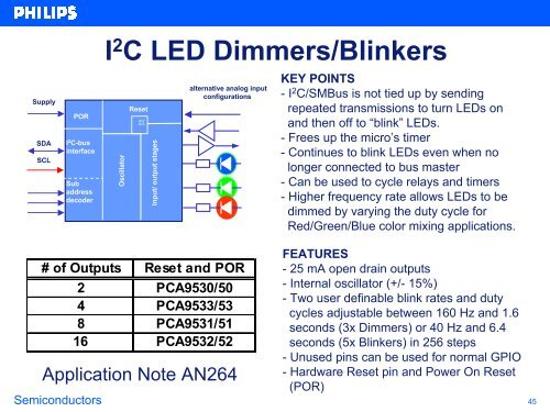
Supply<br />
SDA<br />
SCL<br />
POR<br />
I 2 C-bus<br />
interface<br />
Sub<br />
address<br />
decoder<br />
I 2 C LED Dimmers/Blinkers<br />
Oscillator<br />
Reset<br />
巨<br />
# of Outputs Reset and POR<br />
Input/ output stages<br />
alternative analog input<br />
configurations<br />
2 PCA9530/50<br />
4 PCA9533/53<br />
8 PCA9531/51<br />
16 PCA9532/52<br />
Application Note AN264<br />
KEY POINTS<br />
-I 2 C/SM<strong>Bus</strong> is not tied up by sending<br />
repeated transmissions to turn LEDs on<br />
and <strong>the</strong>n off to “blink” LEDs.<br />
- Frees up <strong>the</strong> micro’s timer<br />
- Continues to blink LEDs even when no<br />
longer connected to bus master<br />
- Can be used to cycle relays and timers<br />
- Higher frequency rate allows LEDs to be<br />
dimmed by varying <strong>the</strong> duty cycle for<br />
Red/Green/Blue color mixing applications.<br />
FEATURES<br />
- 25 mA open drain outputs<br />
- Internal oscillator (+/- 15%)<br />
- Two user definable blink rates and duty<br />
cycles adjustable between 160 Hz and 1.6<br />
seconds (3x Dimmers) or 40 Hz and 6.4<br />
seconds (5x Blinkers) in 256 steps<br />
- Unused pins can be used for normal GPIO<br />
- Hardware Reset pin and Power On Reset<br />
(POR)<br />
Semiconductors 45