How the I2C Bus Works - EEWeb
How the I2C Bus Works - EEWeb
How the I2C Bus Works - EEWeb

You also want an ePaper? Increase the reach of your titles
YUMPU automatically turns print PDFs into web optimized ePapers that Google loves.
PCA9541 - Multi-Point Application<br />
Master 0<br />
PCA9541<br />
PCA9541<br />
PCA9541<br />
PCA9541<br />
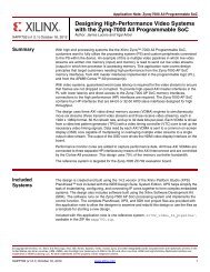
In a typical multi-point application, as shown in <strong>the</strong> diagram, <strong>the</strong> two masters (e.g.,<br />
primary and back-up) are located on separate I 2 C buses that connect to multiple<br />
downstream I 2 C bus slave cards via a PCA9541 to provide high reliability of <strong>the</strong> I 2 C bus.<br />
This way one of <strong>the</strong> controller cards can fail or be removed from <strong>the</strong> system and control<br />
of <strong>the</strong> line cards is maintained. A bent pin or o<strong>the</strong>r hard failure is confined to one bus and<br />
control is maintained on <strong>the</strong> o<strong>the</strong>r bus. I 2 C commands are sent via <strong>the</strong> primary or backup<br />
master and ei<strong>the</strong>r master at any time can gain control of <strong>the</strong> slave devices if <strong>the</strong> o<strong>the</strong>r<br />
master is disabled or removed from <strong>the</strong> system. The failed master is isolated from <strong>the</strong><br />
system and will not affect communication between <strong>the</strong> on-line master and <strong>the</strong> slave<br />
devices located on <strong>the</strong> line cards.<br />
Semiconductors 61<br />
PCA9541<br />
PCA9541<br />
PCA9541<br />
PCA9541<br />
Master 1