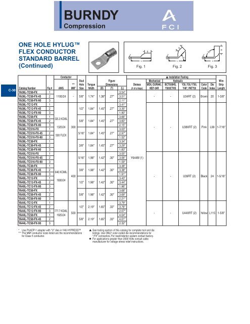
BURNDY - Nedco
BURNDY - Nedco
BURNDY - Nedco

Create successful ePaper yourself
Turn your PDF publications into a flip-book with our unique Google optimized e-Paper software.
C-30<br />
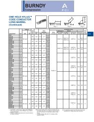
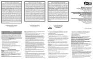
ONE HOLE HYLUG<br />
FLEX CONDUCTOR<br />
STANDARD BARREL<br />
(Continued)<br />
* Use PUADP-1 adapter with "U" dies in Y46 HYPRESS<br />
*** The MM 2 conductor sizes listed are the recommendations<br />
for Class 5 conductor.<br />
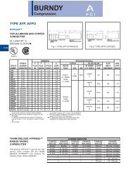
<strong>BURNDY</strong><br />
Compression<br />
Conductor ▲ Installation Tooling<br />
Stud Figure Mechanical Hydraulic Wire<br />
*** Hole Tongue Dimensions Dieless MD6, OUR840, BCT500HS, Y35, Y39, Y750, Color Die Strip<br />
Catalog Number Fig # AWG MM2 Size Width (B) (T) (L) (# of crimps) MD7-34R Y500CTHS Y46*, PAT750 Code Index Length<br />
YA36L-TC58-FX 1 3.54<br />
YA36L-TC58-FX-45 2 1100/24 - 5/8 1.74 1.38 .27 3.51 - - U34RT (2) Brown 20 1-3/8<br />
YA36L-TC58-FX-90 3 2.11<br />
YA38L-TC12-FX 1 3.41<br />
YA38L-TC12-FX-45 2 1/2 1.84 1.45 .27 3.35<br />
YA38L-TC12-FX-90 3 1.90<br />
YA38L-TC58-FX<br />
YA38L-TC58-FX-45<br />
1<br />
2<br />
535.3 KCMIL<br />
5/8 1.84 1.45 .27<br />
3.66<br />
3.60<br />
YA38L-TC58-FX-90<br />
YA38L-TC516-FX<br />
3<br />
1<br />
1325/24 300<br />
2.15<br />
3.03<br />
- - U38XRT (2) Pink L99 1-7/16<br />
YA38L-TC516-FX-45<br />
YA38L-TC516-FX-90<br />
2<br />
3<br />
500 FLEX<br />
5/16 1.84 1.45 .27 2.97<br />
1.52<br />
YA38L-TC38-FX 1 3.34<br />
YA38L-TC38-FX-45 2 3/8 1.84 1.45 .27 3.29<br />
YA38L-TC38-FX-90 3 1.83<br />
YA40L-TC516-FX 1 3.05<br />
YA40L-TC516-FX-45 2 5/16 1.98 1.42 .30 3.06 Y644M (1)<br />
YA40L-TC516-FX-90 3 1.59<br />
YA40L-TC38-FX 1 3.38<br />
YA40L-TC38-FX-45<br />
YA40L-TC38-FX-90<br />
YA40L-TC12-FX<br />
YA40L-TC12-FX-45<br />
2<br />
3<br />
1<br />
2<br />
646 KCMIL<br />
1600/24<br />
400<br />
3/8<br />
1/2<br />
1.98<br />
1.98<br />
1.42<br />
1.42<br />
.30<br />
.30<br />
3.38<br />
1.91<br />
3.43<br />
3.44<br />
- - U39RT (2) Black 24 1-5/16<br />
YA40L-TC12-FX-90 3 1.96<br />
YA40L-TC58-FX 1 3.68<br />
YA40L-TC58-FX-45 2 5/8 1.98 1.42 .30 3.69<br />
YA40L-TC58-FX-90 3 2.21<br />
YA44L-TC12-FX 1 3.79<br />
YA44L-TC12-FX-45 2 1/2 2.19 1.65 .33 3.76<br />
YA44L-TC12-FX-90<br />
YA44L-TC58-FX<br />
3<br />
1<br />
777.7 KCMIL<br />
1925/24<br />
500<br />
2.07<br />
4.04<br />
- - U44XRT (2) Yellow L115 1-5/8<br />
YA44L-TC58-FX-45 2 5/8 2.19 1.65 .33 4.01<br />
YA44L-TC58-FX-90 3 2.32<br />
▲ See tooling section of this catalog for complete tool and die<br />
listings. Use ONLY color-coded die recommendations for<br />
“-FX” connectors. For nest/indentor system contact factory.<br />
◆ For applications greater than 2000 Volts consult cable<br />
manufacturer for voltage stress relief instructions.<br />
T<br />
L<br />
Fig. 1<br />
B<br />
B<br />
T T<br />
45°<br />
L<br />
90°<br />
Fig. 2 Fig. 3<br />
L<br />
B
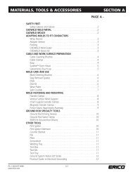
INTRODUCTION<br />
MEDIUM AND LARGE HYDENT<br />
Copper and aluminum compression terminals<br />
and splices for terminating conductors from<br />
#8 AWG through 2000 kcmil.<br />
The medium and large HYDENT line is<br />
designed for terminating and splicing medium<br />
and large conductors in electrical power<br />
applications.<br />
HYLUG<br />
UNINSULATED COPPER<br />
COMPRESSION TERMINALS<br />
UL LISTED 90° C,<br />
600 VOLTS TO 35 kV ◆<br />
<strong>BURNDY</strong>'s HYLUG terminals, types YA,<br />
YA-TC, YA-L, YA-L-TC, YA-2N, YA-2TC, YA-L-<br />
TC-FX, YA-L-2TC, and YA-2LN are designed<br />
for terminating copper conductors in a wide<br />
variety of electrical connections, including<br />
heavy-duty industrial, utility, commercial, and<br />
telecommunications applications.<br />
The HYLUG terminals require simple cable<br />
preparation for an easily installed permanent<br />
and inspectable cable termination. The terminals<br />
are listed by UL (UL STD. 486A) and<br />
CSA certified to 600 volts, when applied with<br />
the proper tool and die combination. The<br />
terminals may be used in applications to<br />
35KV. See each catalog page for UL 35kV<br />
listings.<br />
<strong>BURNDY</strong><br />
Compression<br />
Features and Benefits<br />
• Manufactured from seamless high<br />
conductivity electrolytic copper tubing<br />
with heavy duty wall thickness.<br />
◊ Provides maximum conductivity, low<br />
resistance and ductility for an excellent<br />
combination of electrical and crimp<br />
forming properties.<br />
• Barrel diameter closely matches<br />
commercial (code) cable and Navy<br />
cable diameters.<br />
◊ Provides an excellent relationship<br />
of the conductor/connector combination<br />
to produce a high quality electrical connection<br />
with the recommended tooling.<br />
• Electro-tin plated. Electro-lead plated.<br />
Burndy’s proprietary brite finish.<br />
◊ Provides durable long-lasting<br />
corrosion resistance.<br />
• Internally beveled barrel end.<br />
◊ Provides easy cable insertion.<br />
• Each connector is clearly marked with<br />
the wire size and type, die index, and<br />
color coding.<br />
◊ Provides easy identification and proper<br />
tooling recommendation.<br />
• Marked with the proper number and<br />
location of crimps.<br />
◊ Lowers installed costs. Provides for<br />
proper installations.<br />
• Proper compression systems forms a<br />
homogeneous mass.<br />
◊ The result is an excellent electrical<br />
connection.<br />
• Use up to 35 kV as indicated.<br />
◊ Suitable for high voltage applications.<br />
• Expanded wire ranges when using<br />
Y644 HYPRESS Dieless “1” Crimp.<br />
◊ Provides ability to complete emergency<br />
repairs when connector and wire size<br />
do not match.<br />
•Crimp areas clearly marked.<br />
◊ Provides correct number and location<br />
of crimps for proper installation.<br />
• Hydraulic and Battery tooling crimp<br />
embossment.<br />
◊ Provides permanent die index number<br />
embossment on completed crimp for<br />
inspection purposes.<br />
C-1
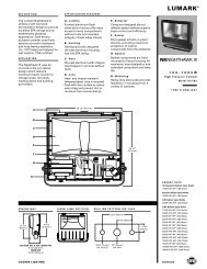
COPPER<br />
ALUMINUM<br />
<strong>BURNDY</strong><br />
Compression<br />
STRANDED<br />
“CODE”<br />
CLASS “B”<br />
CABLE<br />
FLEXIBLE<br />
EXTRA FLEX<br />
Accepts Code and<br />
Flex Cables Up to 4/0<br />
STD. LENGTH<br />
LUGS<br />
LONG<br />
BARREL LUGS<br />
COPPER<br />
SPLICES<br />
REDUCER<br />
ADAPTER<br />
COPPER<br />
TAPS<br />
STD. LENGTH<br />
BARREL LUGS<br />
LONG<br />
BARREL-LUG<br />
PIN<br />
ADAPTER<br />
SPLICE<br />
COPPER<br />
TAPS<br />
LUGS<br />
TRANSFORM.<br />
LUG KIT<br />
STACKING<br />
ADAPTER<br />
PIN<br />
ADAPTER<br />
SPLICES<br />
REDUCERS<br />
TAPS<br />
ONE HOLE YA-L, YA-L-TC C-9 - C14<br />
NARROW TONGUE YA-L-NT C15<br />
NARROW TONGUE TWO HOLE YA-L-2NT C50<br />
TWO HOLE YA-2L, YA-2LN, YA-L-2TC C43 - C49<br />
ONE HOLE YA, YA-TC, YAZ C16 - C24<br />
TWO HOLE YA-2N, YA-2TC, YAZ C51 - C63<br />
FOUR HOLE YA-4N, YAB-4N C85<br />
STANDARD LENGTH YS-L C93<br />
LONG BARREL YS, YS-T, YSP-T C94, C98<br />
REDUCER ADAPTER Y-R C95<br />
TEE YST, NYT C112 - C113<br />
C-TAP YC-C C104<br />
LIGHT DUTY C TAP YC-L C103<br />
ONE HOLE YA-L, YA-L-FX, YAV, YAV-L-FX C25 - C30<br />
ONE HOLE — WIDE BELLED ENTRY YA-LB C31<br />
ONE HOLE — LEAD PLATED YAG-L-TC-LD C32 - C37<br />
TWO HOLE YA-L-2TC-FX, YAV-L-2TC-FX C64 - C70<br />
TWO HOLE-LEAD PLATED YAG-L-2TC-LD C71 - C77<br />
ONE HOLE YA-TC-FXB, YAV-TC-FXB, YAZV C38 - C42<br />
TWO HOLE YA-2TC-FXB, YAV-2TC-FXB, YAZV C78 - C83<br />
PIN ADAPTER YEV-P-FX, YEP-FX, YEP C114 - C116<br />
SPLICE STANDARD LENGTH BELLED YS-LB C96 - C978<br />
LONG BARREL — BELLED YS-FXB C99<br />
C-TAP YCHC C105<br />
H-TAP YH C106 - C108<br />
LONG H TAP YSH C109<br />
COVERS FOR H TAPS CF-FR C110<br />
ONE HOLE YA-A, YA-A-TN C117 - C118<br />
TWO HOLE YA-A C119<br />
YA-A-KIT C120<br />
ASA-U, CUSA C92<br />
STRAIGHT AYP C121 - C122<br />
OFFSET AYPO C121 - C122<br />
STANDARD YS-A C123 - C124<br />
TAPERED FOR HIGH VOLTAGE YS-AT C125<br />
YRB C126<br />
H-TAPS YFD, YFN, YFO, YFR C127<br />
COVERS FOR H TAPS CFA, CFA-FR C128<br />
C-3
C-4<br />
COMPRESSION<br />
CONNECTORS<br />
<strong>BURNDY</strong>'s compression connectors are<br />
designed for reliable and controllable electrical<br />
connections. The complete installation is<br />
fully inspectable. They are high conductivity<br />
copper and operate cooler than the wire on<br />
which they are installed. The connectors withstand<br />
a wide range of electrical and environmental<br />
conditions, including current surges,<br />
temperatures, corrosion and vibrations, for a<br />
wide variety of applications. These features<br />
mean a consistently high quality connection<br />
at a low installed cost.<br />
Copper compression connectors are manufactured<br />
from high-conductivity electrolytic<br />
copper. The connectors are normally tinplated,<br />
lead-plated, or plated with proprietary<br />
<strong>BURNDY</strong> ® brite finish to provide durable<br />
long-lasting corrosion resistance. The connector<br />
design has been matched to the cable<br />
size to provide the necessary physical<br />
strength requirements for reliable electrical<br />
performance.<br />
Aluminum compression connectors are manufactured<br />
from high conductivity, high purity<br />
wrought aluminum. They are designed with<br />
sufficient mass and are electro-tin plated to<br />
minimize corrosion due to galvanic action<br />
between dissimilar metals. The connector<br />
barrels are pre-filled with PENETROX ® ,<br />
<strong>BURNDY</strong>'s oxide inhibiting compound.<br />
PENETROX ® contains homogeneously suspended<br />
metallic particles which penetrate the<br />
wire's oxides to establish excellent continuity<br />
between the individual strands and the<br />
connector barrel for a low-resistance connection.<br />
PENETROX ® maintains an air-tight<br />
connection. Each barrel end is covered with a<br />
color-coded plastic dust cap which prevents<br />
foreign matter from entering the connector<br />
before it is used. The connector design has<br />
been engineered to match the cable size to<br />
provide the necessary physical strength<br />
requirements for reliable electrical performance.<br />
<strong>BURNDY</strong><br />
Compression<br />
SELECTION AND USE<br />
Copper compression connectors are recommended<br />
for use on copper conductors.<br />
Aluminum compression connectors are<br />
recommended for use on aluminum conductors.<br />
Dual-rated aluminum compression<br />
connectors may be used on both copper and<br />
aluminum conductors.<br />
Two basic compression designs are available:<br />
Circumferential and indent.<br />
Circumferential<br />
compression is solid<br />
and symmetrical.<br />
No sharp "Flash".<br />
Indent compression.<br />
The connector is swaged<br />
to the conductor.<br />
After compression, virtually all the air is<br />
removed leaving a tight homogeneous mass<br />
of connector and conductor.<br />
The circumferential crimp design is recommended<br />
for color coded connectors in low<br />
and high voltage applications. Die index<br />
number embossment provides an easy<br />
inspection where required to verify the use of<br />
the proper connector/die combination. It is<br />
also recommended for insulated connectors<br />
and for terminating flexible and welding<br />
cables.<br />
The circumferential crimp design dies compress<br />
cable strands into polygonal shapes<br />
forming intimate contact with each other and<br />
the connector barrel. This compression forms<br />
a tight homogeneous mass with virtually no<br />
air pockets. The circumferential crimp<br />
provides an excellent electrical connection<br />
with high pull-out values. The circumferential<br />
crimp is ideal for high voltage applications<br />
leaving the connector barrel symmetrical,<br />
which is easier to insulate.<br />
The indent type crimp can be used in virtually<br />
any application except polyvinylchloride<br />
(PVC) insulated terminals and splices. It is an<br />
excellent means of terminating flexible, extra<br />
flexible and welding cables. The indentor<br />
compresses the cable strands to form intimate<br />
contact with each other and the<br />
connector barrel. The result is an excellent<br />
electrical connection with high pull-out<br />
strength. Laboratory work testing curves<br />
established the proper depth and shape of<br />
indent for each type of connector and wire<br />
combination.<br />
TOOLING<br />
Tooling systems are essential for proper<br />
installation of a compression connector.<br />
Since connectors and dies are designed as a<br />
unit for specific wire sizes, only the recommended<br />
tools and dies should be used. Most<br />
aluminum and copper HYLUG terminals<br />
and HYLINK splices are marked with a die<br />
index number and are color-coded to identify<br />
the correct installation die. Dies marked with<br />
the matching die index number and color can<br />
be used to install the connector.<br />
<strong>BURNDY</strong> ® tooling installs a wide range of<br />
connectors, is reliable, cost effective, and precision<br />
engineered for durable, long-lasting<br />
service and quality connections. The tools<br />
include small plier types, full cycle ratchet<br />
designs and hydraulically-powered<br />
HYPRESS heads and new Battery<br />
Actuated Tools. Some have permanent die<br />
grooves or adjustable dies, while others<br />
require a change of die sets or nest die for<br />
each connector size. <strong>BURNDY</strong>'s recommended<br />
tools achieve crimp performance consistent<br />
with UL and other industry standards.<br />
Since several tools are suitable for most<br />
connectors, the most economical and practical<br />
tool can be chosen for each application.<br />
INDUSTRY STANDARDS<br />
<strong>BURNDY</strong>'s compression terminals, splices<br />
and tap connectors requiring third party testing<br />
and approval are listed by Underwriters'<br />
Laboratories, Inc. Many have also received<br />
CSA approval and are approved under MIL-<br />
T-7928 and other military standards. All<br />
conform to applicable sections of the National<br />
Electrical Code.<br />
<strong>BURNDY</strong> ® also offers connectors and splices<br />
which meet the (LOCA Seismec and Aging)<br />
requirements of IEEE standards 323, 383<br />
and 344 for class 1E critical circuits for use in<br />
Nuclear Utility Applications. Certification to<br />
10CFR50 and 10CFR21 available.<br />
Detail catalog listings should be consulted to<br />
obtain the appropriate standards for each<br />
connector and splice.
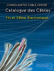
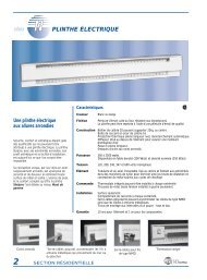
ONE HOLE HYLUG<br />
FLEX CONDUCTOR<br />
STANDARD BARREL<br />
TYPES YA-L, YA-L-FX, YAV,<br />
YAV-L-FX<br />
COPPER COMPRESSION<br />
TERMINAL<br />
UL Listed 90° C,<br />
600 Volts to 35 KV ◆<br />
* Use PUADP-1 adapter with "U" dies in Y46 HYPRESS.<br />
** The MM 2 conductor size listed is for both Class 2 and<br />
Class 5 conductors.<br />
*** The MM 2 conductor sizes listed are the recommendations<br />
for Class 5 conductor.<br />
<strong>BURNDY</strong><br />
Compression<br />
DIE AND COLOR<br />
CODE INFORMATION<br />
INSPECTION<br />
WINDOW<br />
T<br />
BEVELED<br />
ENTRY<br />
CRIMP<br />
ELECTRO-TIN<br />
PLATED CABLE<br />
ACCOMMODATION<br />
L<br />
B<br />
B<br />
T T<br />
45°<br />
L<br />
Fig. 1 Fig. 2 Fig. 3<br />
Conductor ▲ Installation Tooling<br />
Stud Figure Mechanical Hydraulic Wire<br />
*** Hole Tongue Dimensions Dieless MD6, OUR840, BCT500HS, Y35, Y39, Y750, Color Die Strip<br />
Catalog Number Fig # AWG MM2 Size Width (B) (T) (L) (# of crimps) MD7-34R Y500CTHS Y46*, PAT750 Code Index Length<br />
YA8CL-BOX 1 1.16<br />
YA8CL-45 2 8-10 .41 .44 .08 1.16<br />
YA8CL-90 3 .71<br />
YA8C-L1-BOX 1 1.26<br />
YA8C-L1-45 2 1/4 .44 .44 .08 1.24<br />
YA8C-L1-90<br />
YA8C-L2-BOX<br />
YA8C-L2-45<br />
YA8C-L2-90<br />
YA8C-L3-BOX<br />
3<br />
1<br />
2<br />
3<br />
1<br />
37/24<br />
#8 Weld<br />
#8 AWG<br />
**<br />
10<br />
5/16 .52 .44 .08<br />
.80<br />
1.38<br />
1.34<br />
.92<br />
1.51<br />
Y1MR (1)<br />
Y8MRB-1<br />
Y2MR (1)<br />
MY29-11 (1)<br />
W8CVT (1)<br />
W8CRT (1)<br />
X8CRT (1)<br />
W8CVT (1)<br />
W8CRT (1)<br />
X8CRT (1)<br />
U8CRT (1) Red 49 7/16<br />
YA8C-L3-45 2 3/8 .58 .44 .08 1.45<br />
YA8C-L3-90 3 1.04<br />
YA8C-L4-BOX 1 1.76<br />
YA8C-L4-45 2 1/2 .71 .44 .08 1.67<br />
YA8C-L4-90 3 1.28<br />
YAV6CL-TC10-FX 1 1.30<br />
YAV6CL-TC10-FX-45 2 8-10 .48 .50 .08 1.26<br />
YAV6CL-TC10-FX-90 3 .76<br />
YAV6CL-TC12-FX 1 1.86<br />
YAV6CL-TC12-FX-45 2 1/2 .75 .50 .12 1.92<br />
YAV6CL-TC12-FX-90<br />
YAV6CL-TC14-FX<br />
YAV6CL-TC14-FX-45<br />
YAV6CL-TC14-FX-90<br />
YAV6CL-TC38-FX<br />
3<br />
1<br />
2<br />
3<br />
1<br />
61/24<br />
#6 WELD<br />
#6 AWG<br />
**<br />
16<br />
1/4 .48 .50 .08<br />
1.34<br />
1.43<br />
1.39<br />
.88<br />
1.61<br />
Y1MR (1)<br />
Y2MR (1)<br />
MY29-11 (1)<br />
Y644M (1)<br />
W5CVT (1)<br />
W5CRT (1)<br />
X5CRT (1)<br />
W5CVT (1)<br />
W5CRT (1)<br />
X5CRT (1)<br />
U5CRT (1) Blue 7 1/2<br />
YAV6CL-TC38-FX-45 2 3/8 .60 .50 .06 1.54<br />
YAV6CL-TC38-FX-90 3 1.06<br />
YAV6CL-TC516-FX 1 1.49<br />
YAV6CL-TC516-FX-45 2 5/16 .60 .50 0.07 1.44<br />
YAV6CL-TC516-FX-90 3 .94<br />
▲ See tooling section of this catalog for complete tool and die<br />
listings. Use ONLY color-coded die recommendations for<br />
“-FX” connectors. For nest/indentor system contact factory.<br />
◆ For applications greater than 2000 Volts consult cable<br />
manufacturer for voltage stress relief instructions.<br />
90°<br />
L<br />
B<br />
C-25