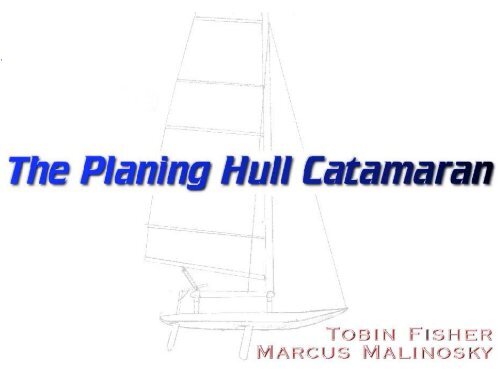
The Planing Hull Catamaran by Tobin Fisher and - MAELabs UCSD
The Planing Hull Catamaran by Tobin Fisher and - MAELabs UCSD
The Planing Hull Catamaran by Tobin Fisher and - MAELabs UCSD
Create successful ePaper yourself
Turn your PDF publications into a flip-book with our unique Google optimized e-Paper software.
<strong>The</strong> <strong>Planing</strong> <strong>Catamaran</strong> Concept<br />
Create a high performance sailboat that combines the best qualities of<br />
windsurfers <strong>and</strong> catamarans<br />
<strong>Catamaran</strong> Windsurfer
<strong>The</strong> <strong>Planing</strong> <strong>Catamaran</strong> Concept
<strong>The</strong> Two Modes of Sailing<br />
1. Displacement Sailing<br />
2. <strong>Planing</strong>
<strong>The</strong> Two Modes of Sailing<br />
Volume of water that must be moved as boat<br />
moves through water creates “form drag”<br />
Total Drag = Skin Drag + Form Drag<br />
Total Drag ∝V 2<br />
1. Displacement Sailing<br />
Above the hull speed total drag ∝V 4<br />
Top speed effectively capped <strong>by</strong> the hull<br />
speed
<strong>The</strong> Two Modes of Sailing<br />
Only skin drag, form drag<br />
becomes negligible<br />
Boat slides over surface of<br />
water like surfboard<br />
Wetted area decreases with<br />
velocity<br />
Drag ∝ V<br />
2. <strong>Planing</strong>
What’s Special About <strong>Catamaran</strong>’s?<br />
Wide beam (width) allows crew to create huge<br />
moments <strong>and</strong> thus boat can carry huge sails for total<br />
weight<br />
Semicircular hulls minimizes skin drag for given<br />
buoyancy<br />
180 lbs<br />
100 lbs<br />
Advantages<br />
100 lbs<br />
Large moment arm<br />
300 lbs
What’s Special About <strong>Catamaran</strong>’s?<br />
Slender semicircular hull shape prevents<br />
hulls from planing<br />
<strong>Hull</strong>s must displace volume of water equal in<br />
weight to boat <strong>and</strong> crew as it moves<br />
Top speed is limited <strong>by</strong> waterline length<br />
180 lbs<br />
100 lbs<br />
Disadvantages<br />
100 lbs<br />
Large moment arm<br />
300 lbs
How About Windsurfers?<br />
Simple design allows total rig to be very light<br />
Flat hull shape promotes planing--hull slips over<br />
surface of water instead of displacing the water<br />
Can travel very fast in high winds<br />
Drag increases linearly with velocity<br />
180 lbs<br />
Small moment arm<br />
Advantages<br />
60 lbs
How About Windsurfers?<br />
Crew cannot generate a very large moment about the<br />
centerboard<br />
Rigs must have very low aspect ratios<br />
Sails are not efficient<br />
Poor light wind performance<br />
Poor upwind sailing capabilities<br />
180 lbs<br />
Disadvantages<br />
Small moment arm<br />
60 lbs
Why A <strong>Catamaran</strong> That Could Plane?<br />
Advantages:<br />
Unlike conventional catamarans, it’s top speed is not limited <strong>by</strong><br />
waterline length<br />
Excellent performance on all points of sail in medium to high<br />
winds (when it is strong enough for the boat to plane)<br />
Disadvantages:<br />
poor light air performance--this is because the flat hulls have a<br />
large amount of surface area to buoyancy <strong>and</strong> have a large amount<br />
of skin drag when not planing
Critical Factors in the Design<br />
SCP = max lift generated <strong>by</strong> sails divided <strong>by</strong> total weight of boat <strong>and</strong><br />
crew. This dimensionless number predicts planing ability <strong>and</strong><br />
performance as a rough rule of thumb:<br />
if SCP < .20 boat will not plane<br />
if SCP > .20 boat can plane on some points of sail<br />
if SCP > .30 boat can plane of most points of sail<br />
<strong>The</strong> bigger the SCP, the better!<br />
Sail Carrying Power (SCP)<br />
What helps create a high SCP? Wide beam <strong>and</strong> light weight<br />
Early estimates for our design yielded an SCP of 0.615!
Critical Factors in the Design<br />
Flat planing surface<br />
Stability<br />
Control<br />
Strength<br />
Other Factors
<strong>The</strong> Design<br />
Early Sketches<br />
Front View Side View
<strong>The</strong> Design<br />
Front View<br />
Innovative Features<br />
Tubing connectors enable<br />
easy adjustment of beam<br />
Use spectra line instead of<br />
wire to reduce weight<br />
Wide trampoline supports<br />
<strong>Hull</strong>s canted at 12 o so hull is<br />
flat when “flying a hull”<br />
Flat hull bottom promotes<br />
early planing
How Did We Build A Sailboat In Thirteen Weeks?<br />
Learned as much as possible from similar existing designs<br />
studied several conventional catamarans of similar size<br />
met with professional catamaran designer <strong>and</strong> national champion<br />
catamaran racer<br />
Used pipe connectors for tubing connections<br />
enables connection of aluminum tubing without time consuming<br />
<strong>and</strong> permanent welding<br />
aid experimentation <strong>by</strong> making adjustments <strong>and</strong> part replacement<br />
relatively fast <strong>and</strong> easy<br />
Know what you have to make yourself <strong>and</strong> what you can buy<br />
Use windsurfers for the hulls<br />
Take mast, sail, <strong>and</strong> hardware off an old catamaran (Prindle 16)<br />
buy other stock sailing hardware (travelers, shackles) to meet needs
Elements That Needed To Be Designed<br />
trampoline<br />
trampoline frame<br />
trampoline supports<br />
Connectors to<br />
windsurfing boards<br />
Rudders <strong>and</strong><br />
centerboards
<strong>The</strong> Rudders<br />
How A Rudder Works<br />
As boat slips through the water, lift is produced<br />
according to Bernoulli's Principle. A high <strong>and</strong> low<br />
pressure region are created on either side of the foil<br />
because of the different velocities of the fluid. This<br />
pressure difference creates lift.<br />
Without leeway, there is no lift generated <strong>by</strong> the foil.<br />
You will always have leeway no matter how good<br />
your centerboard is. A good centerboard will make<br />
the leeway angle as small as possible.
<strong>The</strong> Rudders Motion Of Fluid<br />
Motion of the fluid past the centerboard <strong>and</strong> rudder
Design Of Rudder Optimization Goals<br />
To design a rudder <strong>and</strong> centerboard system that will<br />
allow the boat to go the fastest while still being able to<br />
keep the vessel under control.<br />
Optimization Goals:<br />
1. Drag of the system<br />
2. Weight of the system
Design Of Rudder Choice Of Foil<br />
NACA 0009 Foil<br />
Foil is symmetric<br />
Location of asymmetry<br />
Thickness in percentage of chord<br />
Properties<br />
C L MAX ≈ 1.20<br />
α at max = 17.5 o<br />
Had to choose a shape that would produce enough lift <strong>and</strong> minimize drag while still turning the<br />
boat. Wanted smooth leading edge <strong>and</strong> sharp trailing edge. Smooth leading edge will create<br />
extended laminar flow <strong>and</strong> delay stalling<br />
I looked to see what foil shapes were used in industry <strong>by</strong> boats that were comparable in size to<br />
ours. Found that most companies use the NACA 0009 or NACA 0012 foil shape ( the thickness<br />
of the foil is proportional to the chord length ) .
Placement Of Rudder<br />
1. Hang rudders off the stern of the boat<br />
Options<br />
2. Attach rudders below the hull near the stern of the boat
Placement Of Rudder<br />
1. Hang Rudders Off Stern<br />
Susceptible to ventilation<br />
Great for pleasure craft where boat has to be pulled up on s<strong>and</strong>, etc.<br />
Easy to attach turning system<br />
Has largest possible moment arm for steering
Placement Of Rudder<br />
2. Attach Rudders Below <strong>Hull</strong><br />
Creates ‘end plate’ effect<br />
No ventilation<br />
Hard to attach turning system to<br />
rudder
Placement Of Rudder<br />
End Plate Effect<br />
Tip vortices at the end of the<br />
rudder reduce lift <strong>and</strong><br />
increase drag. By having one<br />
end placed against the hull<br />
the rudder can be smaller <strong>and</strong><br />
lighter. Combat this effect<br />
with high aspect ratio.
Placement Of Rudder Tip Loss In Wind Tunnel<br />
Top View Of Tip Vortices In Wind Tunnel
Placement Of Rudder Effective Keel<br />
<strong>The</strong> end plate effect increases<br />
the surface area of the rudder<br />
<strong>by</strong> approximately 20%.<br />
<strong>The</strong>refore the rudder can be<br />
smaller <strong>and</strong> lighter
Placement Of Rudder<br />
We decided that it was better to<br />
place the rudder under the hull<br />
<strong>and</strong> take advantage of the “end<br />
plate” effect. This allows our<br />
rudders to be smaller <strong>and</strong><br />
lightweight while still producing<br />
an adequate amount of lift to keep<br />
the sailor in control of the craft.<br />
Picture of rudder in place under the hull<br />
Decision
Design Of Rudders<br />
We made three sets of rudders so that they could be compared to one<br />
another <strong>and</strong> the optimum shape could be extracted from the results of<br />
the tests.<br />
Shape Average Chord Span Aspect Ratio<br />
Small 5.5’’ 15’’ 2.7<br />
Medium 5.5’’ 17’’ 3.0<br />
Large 5.5’’ 22’’ 4.0<br />
Aspect Ratio = Span / Average Chord<br />
Rudder Shapes
Design Of Rudders<br />
Design Process<br />
Marine Grade Plywood was chosen for the the core of the rudder<br />
because of it’s low cost <strong>and</strong> ease to work with. Other materials used<br />
for the core in industry include hard woods <strong>and</strong> foams.<br />
We used a mill to create the airfoil shape in the plywood then s<strong>and</strong>ed<br />
it down until eventually the rough shape was achieved.
Design Of Rudders<br />
Design Process<br />
Problem: <strong>The</strong> steering rod would twist <strong>and</strong> rip out of the rudder.<br />
We tested the rudders <strong>and</strong> found that the steering rod could not support<br />
the load. To get around this we drilled a hole 11’’ into the rudder for<br />
the tiller to sit. We added a layer of Kevlar in order to increase the<br />
rudders resistance to bending <strong>and</strong> hold the threaded rod in place <strong>and</strong><br />
eliminated the problem.
<strong>The</strong> Connection System<br />
Connects windsurfer boards to trampoline supports <strong>and</strong> trampoline<br />
frame<br />
Needed to estimate loads so connections<br />
could be tested accurately<br />
How do you make rigid connection with<br />
foam <strong>and</strong> plastic board?<br />
Connection needs to be adjustable so the<br />
rig can be moved forward <strong>and</strong> backward<br />
Main Design Issues
<strong>The</strong> Connection System<br />
Epoxy<br />
8 in<br />
Trampoline Supports<br />
Keyed Anchors<br />
Plastic <strong>Hull</strong><br />
Multiple attachment points<br />
Foam<br />
Attachment Points<br />
Spaced as wide as<br />
possible to minimize<br />
forces created <strong>by</strong><br />
moments
Trampoline Design<br />
Supports<br />
Lifts the trampoline above the hulls <strong>and</strong> the water <strong>and</strong> hold the board at<br />
a fixed cant angle<br />
Went with design that had a fixed cant angle of 12 degrees <strong>and</strong> held the<br />
trampoline 1’3’’ over the surface of the water<br />
Lightweight 6061 T6 Aluminum Tubing<br />
Welded Connections
Trampoline Design<br />
Trampoline Frame<br />
Deflections at tip should be < 1 inch<br />
y = -(1/3)(Wl 3 )/(EI)<br />
EI = 1.086×10 7 lb × in 2<br />
For 3” diameter steel tube:<br />
wall thickness must be .0044 in<br />
total weight for 7 foot tube = 2.01 lbs<br />
For 2” diameter steel tube:<br />
wall thickness must be .015 in<br />
total weight for 7 foot tube = 4.76 lbs<br />
For 3” diameter aluminum tube:<br />
wall thickness must be .0128 in<br />
total weight for 7 foot tube = 2.05 lbs<br />
250 lbs
Trampoline Design Final Decisions<br />
Cost for 14 feet 3” diameter aluminum tube: $200<br />
Total weight: 2.05 lbs<br />
Cost for 14 feet 1.9” diameter aluminum tube with .145 wall thickness from<br />
the student shop: $43<br />
Total weight = 7.47 lbs<br />
Deflection = 1.5 inches<br />
Other Advantages of 1.9” tubing<br />
thicker walls means that bolts can be threaded directly into tube walls<br />
1.9” tubing fits in st<strong>and</strong>ard pipe connectors<br />
it was available right away<br />
lower aerodynamic resistance
Trampoline Design Key Features<br />
<strong>The</strong> trampoline is tightly stretched fabric that the sailor can sit on<br />
polypropylene fabric is strong, light, has minimal stretch <strong>and</strong> does<br />
not absorb water<br />
coarse basket weave allows waves to pass through fabric without<br />
collecting<br />
stainless steel grommets will not corrode <strong>and</strong> prevent fabric from<br />
ripping<br />
nylon thread used to support grommets is light <strong>and</strong> will not stretch<br />
when wet<br />
twists in the lacing help keep grommets from pulling out
Design Of Steering System<br />
Diagram of 4-Bar Linkage<br />
Conceptual Design<br />
We decided the best way to<br />
build the steering system<br />
was to use a traditional fourbar<br />
linkage. <strong>The</strong> major<br />
requirement was that the<br />
rudders could be easily taken<br />
in <strong>and</strong> out for testing.
Design Of Steering System<br />
Diagram of bearing<br />
Conceptual Design<br />
Bearing through the<br />
hull of the boat
Design Of Steering System<br />
Rear View of 4-bar linkage<br />
Steering System
Design Of Steering System<br />
Side view of tiller <strong>and</strong> tiller extension<br />
Steering System
Design Of Steering System<br />
Problems:<br />
Too much stress at point were tiller leaves rudder<br />
Had to put tiller through center of lift of rudder, can’t feel the<br />
force on the rudder.<br />
Bearing surface needs to be better.<br />
Solutions:<br />
Use a bearing of Teflon on Teflon<br />
Analysis Of Design<br />
Will be easier to make since the rudders won’t be interchanged
So How Did It Work?
It Did Have Some Problems …
Problems And Solutions<br />
Boat pitches bow over stern when tacking in strong wind<br />
Solutions:<br />
move rig forward<br />
keep weight forward when tacking<br />
decrease mast rake<br />
add buoyancy to stern<br />
cut mast down or use lighter mast<br />
Boat Gets Stuck “in irons” when tacking<br />
Solutions:<br />
move rig forward<br />
move centerboard back<br />
move rudder back<br />
make rudder bigger<br />
add jib
Problems And Solutions<br />
<strong>Hull</strong>s twist <strong>and</strong> flex in waves<br />
Solutions:<br />
use fiberglass poles to stiffen hulls<br />
use bracing wires to prevent flexion of trampoline frame<br />
use stiffer beams for trampoline frame
Thanks !<br />
Dr. Nathan Delson Dr. Gary Povirk<br />
Dr. S<strong>and</strong>ros Gomez Dr. Kailasnath Purushothaman<br />
Dr. Juan De La Mora Christopher White<br />
<strong>and</strong> special thanks to:<br />
Nick Bernardo


