DSP Implementation of an Improved DTC Technique for Induction ...
DSP Implementation of an Improved DTC Technique for Induction ...
DSP Implementation of an Improved DTC Technique for Induction ...

You also want an ePaper? Increase the reach of your titles
YUMPU automatically turns print PDFs into web optimized ePapers that Google loves.
Abstract<br />
<strong>DSP</strong> <strong>Implementation</strong> <strong>of</strong> <strong>an</strong> <strong>Improved</strong> <strong>DTC</strong> <strong>Technique</strong> <strong>for</strong><br />
<strong>Induction</strong> Motor Drives<br />
H.I. Okumus & D. Holliday<br />
University <strong>of</strong> Bristol<br />
Department <strong>of</strong> Electrical & Electronic Engineering<br />
University Walk, Queens Building<br />
BS8 1TR Bristol, UK<br />
H.I.Okumus@bristol.ac.uk Fax: + 44 (0) 117 954 5206<br />
D.Holliday@bristol.ac.uk Fax: + 44 (0) 117 954 5206<br />
A simple stator resist<strong>an</strong>ce voltage-drop compensation method that eliminates the stator resist<strong>an</strong>ce voltage-drop at<br />
low speed in a Direct Torque Controlled induction motor drive is proposed. The resulting “stator voltage drop<br />
feedback” is used to correct the stator flux estimate resulting in a reduced low speed flux ripple. The per<strong>for</strong>m<strong>an</strong>ce<br />
<strong>of</strong> the technique is <strong>an</strong>alysed by simulation <strong>an</strong>d validated by experiments. A low-cost, commercial TMS320C31<br />
<strong>DSP</strong> board is used <strong>for</strong> the implementation <strong>of</strong> the control algorithm.<br />
Introduction<br />
Technological improvements in power semiconductor <strong>an</strong>d microprocessor technology have facilitated the<br />
application <strong>of</strong> adv<strong>an</strong>ced control techniques to ac motor drive systems [1]. There exist two main types <strong>of</strong> highper<strong>for</strong>m<strong>an</strong>ce<br />
torque controlled ac drives: Vector Controlled drives <strong>an</strong>d Direct Torque Controlled (<strong>DTC</strong>) drives [2].<br />
Although the principles <strong>of</strong> <strong>DTC</strong> were introduced more th<strong>an</strong> ten years ago [3,4] it is only recently that industrial<br />
<strong>DTC</strong> drives have become available [5].<br />
Direct Torque Control (<strong>DTC</strong>) has received the attention <strong>of</strong> motor drive designers due to its relatively simple<br />
implementation. The strategy also has the adv<strong>an</strong>tage that it does not require a rotor position sensor. Recent trends<br />
<strong>an</strong>d developments are such that speed <strong>an</strong>d position sensorless high dynamic per<strong>for</strong>m<strong>an</strong>ce drives are attracting<br />
considerable interest due to factors such as increased reliability <strong>an</strong>d cost reduction which c<strong>an</strong> result from the<br />
elimination <strong>of</strong> the speed tr<strong>an</strong>sducer [5].<br />
The <strong>DTC</strong> technique requires a measurement <strong>of</strong> the machine’s stator resist<strong>an</strong>ce to facilitate the estimation <strong>of</strong> the<br />
stator flux. An accurate estimate <strong>of</strong> flux linkage is possible at high operating speed [6] but is less accurate at low<br />
speed. This paper describes a simple technique that eliminates the stator resist<strong>an</strong>ce voltage-drop thereby<br />
improving the estimated value <strong>of</strong> flux linkage, particularly at low speed. The per<strong>for</strong>m<strong>an</strong>ce <strong>of</strong> a <strong>DTC</strong> drive<br />
incorporating the “voltage drop feedback” method is <strong>an</strong>alysed by simulation <strong>an</strong>d validated by experiment.<br />
General Description <strong>of</strong> Direct Torque Control<br />
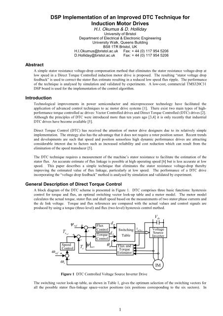
A block diagram <strong>of</strong> the <strong>DTC</strong> scheme is presented in Figure 1. <strong>DTC</strong> comprises three basic functions: hysteresis<br />
control <strong>for</strong> torque <strong>an</strong>d flux, <strong>an</strong> optimal switching vector look-up table <strong>an</strong>d a motor model. The motor model<br />
calculates the actual torque, stator flux <strong>an</strong>d shaft speed based on the measurements <strong>of</strong> two stator phase currents <strong>an</strong>d<br />
the dc link voltage. Torque <strong>an</strong>d flux references are compared with the actual values <strong>an</strong>d control signals are<br />
produced by using a torque (three-level) <strong>an</strong>d flux (two-level) hysteresis control method.<br />
ω ref<br />
Teref<br />
ψ ref<br />
Speed<br />
Control<br />
+<br />
ω r<br />
-<br />
+<br />
+<br />
-<br />
Te<br />
-<br />
ψ act<br />
Flux<br />
Control<br />
Torque<br />
Control<br />
θψ<br />
dψ<br />
dT<br />
Switching<br />
Table<br />
Flux <strong>an</strong>d<br />
Torque<br />
Estimator<br />
Figure 1 <strong>DTC</strong> Controlled Voltage Source Inverter Drive<br />
The switching vector look-up table, as shown in Table 1, gives the optimum selection <strong>of</strong> the switching vectors <strong>for</strong><br />
all the possible stator flux-linkage space-vector positions (six positions corresponding to the six sectors). In<br />
1<br />
S<br />
a,<br />
b,<br />
c<br />
Vdc<br />
Voltage<br />
Source<br />
Inverter<br />
IM
switching Table 1, dψ = 1 <strong>an</strong>d dψ = 0 indicates the stator flux needs to be increased <strong>an</strong>d reduced respectively.<br />
Similarly, dT = 1 indicates the motor torque needs to be increased, <strong>an</strong>d dT = 0 <strong>an</strong>d dT = -1 indicate the torque needs<br />
to be reduced slowly <strong>an</strong>d quickly respectively. Speed control is achieved using a PI controller. In a <strong>DTC</strong> drive, as<br />
shown in Figure 1, the torque reference is also obtained from the PI speed controller.<br />
Table 1 Stator Voltage Switching Table.<br />
<strong>Induction</strong> Motor Model in the Stationary Reference Frame<br />
The stationary reference frame induction motor model, with stator <strong>an</strong>d rotor fluxes as state variables, is defined by<br />
equation (1) <strong>an</strong>d <strong>for</strong>ms the basis <strong>for</strong> the simulation results in this paper.<br />
d<br />
dt<br />
⎡<br />
⎢<br />
⎣<br />
s<br />
r<br />
⎡ Rs<br />
⎢ −<br />
⎤<br />
⎢<br />
s<br />
⎥ =<br />
⎦ ⎢ Rr<br />
M<br />
⎢<br />
⎣ s<br />
Lr<br />
Rs<br />
M ⎤<br />
⎥<br />
s<br />
Lr<br />
⎥<br />
⎡<br />
⎛ R ⎢<br />
r ⎞⎥<br />
j ⎣<br />
⎜ r −<br />
⎟<br />
⎟⎥<br />
⎝<br />
r ⎠⎦<br />
s<br />
r<br />
⎤ ⎡1⎤<br />
⎥ + ⎢ ⎥V<br />
⎦ ⎣0⎦<br />
where s <strong>an</strong>d r are stator <strong>an</strong>d rotor flux space vectors, s V is stator voltage space vector, s R <strong>an</strong>d R r are the<br />
stator <strong>an</strong>d rotor resist<strong>an</strong>ces, L s <strong>an</strong>d L r are stator <strong>an</strong>d rotor self-induct<strong>an</strong>ces, M is the mutual induct<strong>an</strong>ce,<br />
2<br />
= 1 - M Ls<br />
Lr<br />
is the leakage coefficient <strong>an</strong>d r<br />
calculated from equations (2) <strong>an</strong>d (3) respectively.<br />
i<br />
i<br />
ds<br />
qs<br />
2<br />
s<br />
is rotor <strong>an</strong>gular speed. Stator dq current components are<br />
ds − md<br />
= (2)<br />
L − M<br />
s<br />
qs − mq<br />
= (3)<br />
L − M<br />
s<br />
X aq X aq<br />
X aq X aq<br />
where, md = ds +<br />
dr , mq =<br />
qs +<br />
qr<br />
L − M L − M<br />
L − M L − M<br />
s<br />
<strong>an</strong>d [ ] 1 −<br />
X = ( 1/M + 1/ ( L − M ) + 1/ ( L − M ) .<br />
aq<br />
dψ dT N1 N2 N3 N4 N5 N6<br />
1 V2(110) V3(010) V4(011) V5(001) V6(101) V1(100)<br />
1 0 V7(111) V0(000) V7(111) V0(000) V7(111) V0(000)<br />
-1 V6(101) V1(100) V2(110) V3(010) V4(011) V5(001)<br />
1 V3(010) V4(011) V5(001) V6(101) V1(100) V2(110)<br />
0 0 V0(000) V7(111) V0(000) V7(111) V0(000) V7(111)<br />
-1 V5(001) V6(101) V1(100) V2(110) V3(010) V4(011)<br />
s<br />
r<br />
r<br />
s<br />
The electromagnetic torque c<strong>an</strong> be expressed in terms <strong>of</strong> stator flux <strong>an</strong>d current as shown in equation (4)<br />
( i i )<br />
⎛ 3 ⎞⎛<br />
P ⎞<br />
Te = ⎜ ⎟⎜<br />
⎟ ds qs −<br />
⎝ 2 ⎠⎝<br />
2 ⎠<br />
qs ds<br />
where P is the number <strong>of</strong> poles in the induction motor.<br />
Compensation <strong>of</strong> the Effect <strong>of</strong> the Stator Voltage-Drop<br />
A major problem in the application <strong>of</strong> <strong>DTC</strong> at low motor speed is the effect <strong>of</strong> the IsRs voltage drop. In order to<br />
improve flux control at low speed, optimum switching vector selection <strong>an</strong>d a technique that eliminates the effects<br />
<strong>of</strong> the IsRs voltage drop in the machine stator is there<strong>for</strong>e considered.<br />
Figure 2 shows the switching voltage space vectors <strong>an</strong>d stator resist<strong>an</strong>ce voltage drop. It c<strong>an</strong> be seen that at high<br />
speed, the amplitude <strong>of</strong> the stator voltage vector sh V is large <strong>an</strong>d the voltage drop across R s is relatively small <strong>an</strong>d<br />
c<strong>an</strong> be neglected, as shown in Figure 2(a). However, it c<strong>an</strong> be seen from Figure 2(b) that, at low speed, the voltage<br />
drop across s R may be the major portion <strong>of</strong> measured terminal voltage V sl . Moreover, as the temperature <strong>of</strong> the<br />
r<br />
(1)<br />
(4)
stator windings increases, the value <strong>of</strong> resist<strong>an</strong>ce Rs will ch<strong>an</strong>ge signific<strong>an</strong>tly resulting in improper flux estimation<br />
<strong>an</strong>d deterioration in controller per<strong>for</strong>m<strong>an</strong>ce.<br />
sQ<br />
(a) High Speed (b) Low Speed<br />
Figure 2 Effect <strong>of</strong> the Voltage Drop on the Stator Voltage Space Vectors.<br />
Flux Estimator with Voltage-Drop Feedback<br />
In classical <strong>DTC</strong> methods the stator flux is calculated by me<strong>an</strong>s <strong>of</strong> the stator voltage vector <strong>an</strong>d current [7] as<br />
shown in equation (5)<br />
= V R I dt<br />
s<br />
∫ ( − )<br />
(5)<br />
s s s<br />
This gives <strong>an</strong> accurate flux linkage estimate at high speed. However, as described in the previous section, errors in<br />
the flux estimate increase as motor speed reduces.<br />
To compensate the RsIs voltage drop at low speed, a measurement <strong>of</strong> the stator winding resist<strong>an</strong>ce voltage drop is<br />
incorporated into the flux estimator. It c<strong>an</strong> be seen from Figure 2 that the stator voltage drop vector is the function<br />
<strong>of</strong> the stator current. The voltage drop vector c<strong>an</strong> there<strong>for</strong>e be calculated from a present stator current sample <strong>an</strong>d<br />
used as feedback to compensate the present voltage drop at the next sample inst<strong>an</strong>t. The improved flux estimator<br />
is described by equation (6).<br />
Simulation Results<br />
vqsh<br />
I<br />
α<br />
v<br />
dsh<br />
V − R I<br />
s<br />
Vsh<br />
sh<br />
α<br />
s s<br />
RsI<br />
s<br />
sD<br />
= V k R I k I k 1 dt<br />
s<br />
∫[<br />
( ) − ( ( ) − ( − ))]<br />
(6)<br />
s s s s<br />
Simulation studies were carried out using the MATLAB s<strong>of</strong>tware package. Figures 3, 4 <strong>an</strong>d 5 show a comparison<br />
between the proposed compensation strategy <strong>an</strong>d the classical <strong>DTC</strong> scheme. Torque <strong>an</strong>d speed responses <strong>of</strong> both<br />
schemes are shown in Figure 3. It c<strong>an</strong> be observed that there is no signific<strong>an</strong>t difference between both schemes.<br />
Figure 4(a) shows that the compensation technique results in a sinusoidal stator flux wave<strong>for</strong>m whilst Figure 4(b)<br />
shows that the flux wave<strong>for</strong>m obtained from the conventional <strong>DTC</strong> implementation is clearly not sinusoidal. Also,<br />
it may be seen that, with the modified <strong>DTC</strong> strategy, the actual stator flux magnitude is equal to the reference value<br />
<strong>of</strong> 0.8Wb whilst with the classical method there is a signific<strong>an</strong>t error between the two flux values. Figure 5(a)<br />
shows a that the stator flux vector locus is circular compared to the conventional, hexagonal flux locus <strong>of</strong> Figure<br />
5(b).<br />
speed (rad/s) <strong>an</strong>d torque (Nm)<br />
torque (Nm)<br />
2<br />
1<br />
0<br />
20<br />
10<br />
0<br />
-10<br />
0.05 0.1 0.15<br />
time (sec.)<br />
0.2 0.25<br />
speed<br />
torque<br />
0.05 0.1 0.15 0.2<br />
time (sec.)<br />
3<br />
speed (rad/s), torque (Nm)<br />
torque (Nm)<br />
vqsl<br />
2<br />
1<br />
sQ<br />
α<br />
vdsl<br />
Vsl<br />
V − R I<br />
sl<br />
α<br />
Is<br />
s<br />
RsI<br />
s<br />
s<br />
sD<br />
0<br />
0 0.05 0.1 0.15 0.2 0.25<br />
time (sec.)<br />
20<br />
10<br />
0<br />
-10<br />
speed<br />
torque<br />
0.05 0.1 0.15 0.2 0.25<br />
time (sec.)<br />
(a) Proposed Method (b) Conventional Method<br />
Figure 3 Torque <strong>an</strong>d Speed Responses <strong>of</strong> <strong>Induction</strong> Motor (ωr =20 rad/s <strong>an</strong>d TL=1.2 Nm).
stator d-axis flux (Wb)<br />
stator d-axis current (A)<br />
(a) Proposed Method (b) Conventional Method<br />
Figure 4 Phase Current <strong>an</strong>d d-axis Stator Flux (ωr =20 rad/s <strong>an</strong>d TL=1.2 Nm).<br />
0.5<br />
-0.5<br />
(a) Proposed Method (b) Conventional Method<br />
Figure 5 Stator Flux Trajectories <strong>of</strong> <strong>Induction</strong> Motor (ωr =20 rad/s <strong>an</strong>d TL=1.2 Nm).<br />
Experimental Results<br />
1<br />
0<br />
-1<br />
0.5<br />
0<br />
-0.5<br />
0.1 0.2 0.3<br />
time (sec.)<br />
0.4<br />
0.1 0.2 0.3<br />
time (sec.)<br />
0.4 0.5<br />
q-axis stator flux (Wb)<br />
1<br />
0<br />
-1<br />
-1 -0.5 0 0.5 1<br />
d-axis stator flux (Wb)<br />
Experimental tests were carried out on a 0.37kW squirrel-cage induction motor using a TMS320C31 floating point<br />
Digital Signal Processor (<strong>DSP</strong>) as the controller. The basic TMS320C31 <strong>DSP</strong> has been modified by the addition<br />
<strong>of</strong> 64k-words <strong>of</strong> memory, <strong>an</strong> 8-ch<strong>an</strong>nel Analogue to Digital Converter (ADC) <strong>an</strong>d 4-ch<strong>an</strong>nel Digital to Analogue<br />
Converter (DAC). The communication between the external board <strong>an</strong>d the <strong>DSP</strong> board is per<strong>for</strong>med by “built-in”<br />
control signals <strong>an</strong>d external user ports.<br />
The modified <strong>DTC</strong> method is compared with conventional <strong>DTC</strong> under the same operating conditions. The torque<br />
<strong>an</strong>d speed responses <strong>of</strong> both schemes are shown in Figure 6. It c<strong>an</strong> be observed that there is no signific<strong>an</strong>t<br />
difference between the responses under each <strong>of</strong> the schemes. Figure 8 illustrates the stator current wave<strong>for</strong>ms<br />
obtained using both the proposed <strong>DTC</strong> method <strong>an</strong>d conventional <strong>DTC</strong>. Figure 7(a) shows that the current<br />
wave<strong>for</strong>m is more sinusoidal under the proposed <strong>DTC</strong> scheme. The experimental results <strong>for</strong> stator flux locus are<br />
shown in Figure 8. It c<strong>an</strong> be seen from Figure 8(a) that the stator flux trajectory is more circular th<strong>an</strong> that under<br />
the conventional <strong>DTC</strong> scheme.<br />
1V=2.35rad/s<br />
1V=0.25Nm<br />
q-axis stator flux (Wb)<br />
4<br />
stator d-axis flux (Wb)<br />
1<br />
0.5<br />
0<br />
-0.5<br />
stator d-axis current (A)<br />
2<br />
1<br />
0<br />
-1<br />
-2<br />
0.05 0.1 0.15 0.2 0.25 0.3 0.35<br />
time (sec.)<br />
0.5<br />
0<br />
-0.5<br />
0.05 0.1 0.15 0.2 0.25 0.3 0.35<br />
time (sec.)<br />
-1<br />
-1 -0.5 0 0.5 1<br />
d-axis stator flux (Wb)<br />
1V=2.35rad/s<br />
1V=0.25Nm<br />
(a) Proposed Method (b) Conventional Method<br />
Figure 6 Torque <strong>an</strong>d Speed Responses <strong>of</strong> <strong>Induction</strong> Motor (ωref =20 rad/s <strong>an</strong>d TL=1.2 Nm).
(a) Proposed Method (b) Conventional Method<br />
Figure 7 Phase Current <strong>of</strong> <strong>Induction</strong> Motor (ωref =20 rad/s <strong>an</strong>d TL=1.2 Nm).<br />
(a) Proposed Method (b) Conventional Method<br />
Figure 8 Stator Flux Trajectories <strong>of</strong> <strong>Induction</strong> Motor (ψref = 0.8Wb)<br />
Conclusion<br />
In this paper, a new compensation strategy <strong>for</strong> Direct Torque Control <strong>of</strong> induction motor has been presented. The<br />
results have been compared with those obtained using conventional <strong>DTC</strong> under the same operating conditions.<br />
Simulation <strong>an</strong>d experimental results show that the new strategy c<strong>an</strong> be applied to <strong>DTC</strong> to improve the flux control<br />
at low speeds.<br />
Acknowledgements<br />
The authors would like to acknowledge the University <strong>of</strong> Bristol <strong>for</strong> support <strong>an</strong>d the use <strong>of</strong> facilities. Th<strong>an</strong>ks are<br />
also due to Dr. Naim Dahnoun <strong>for</strong> his useful discussion regarding <strong>DSP</strong>.<br />
References<br />
1V=0.4A<br />
[1] Ludtke, M.G. Jayne, “A New Direct Torque Control Strategy”, IEE, Savoy Place, London 1995, pp. 5/1-5/4.<br />
[2] P. Vas, “Vector Control <strong>of</strong> ac Machines”, Ox<strong>for</strong>d University Press, 1990.<br />
[3] M<strong>an</strong>fred Depenbrock, “Direct Self Control (DSC) <strong>of</strong> Inverter-Fed <strong>Induction</strong> Machine IEEE Tr<strong>an</strong>s. on Power<br />
Electronics, Vol. 3, No. 4, October 1992, pp. 420-429.<br />
[4] I. Takahashi, T. Noguchi, “A New Quick-Response <strong>an</strong>d High-Efficiency Control Strategy <strong>of</strong> <strong>an</strong> <strong>Induction</strong><br />
Motor”, IEEE Tr<strong>an</strong>s. on Industry Applications, Vol.IA-22, No. 5, September/October 1986, pp. 820-827.<br />
[5] P. Vas, “Sensorless vector <strong>an</strong>d direct torque control”, Ox<strong>for</strong>d University Press, 1998.<br />
[6] A. Monti, F. Pironi, F. Sartogo, P. Vas, “A New State Observer For Sensorless <strong>DTC</strong> Control”, Power<br />
Electronics <strong>an</strong>d Variable Speed Drives, 21-23 September 1998, No. 456, pp. 311-17.<br />
[7] J.R.G. Sch<strong>of</strong>ield, “Variable speed drives using induction motors <strong>an</strong>d direct torque control”, ABB Industrial<br />
Systems Ltd., IEE, Savoy Place, London 1998, pp. 5/1-5/7.<br />
5<br />
1V=0.4A<br />
1V=0.2Wb 1V=0.2Wb