ECL Comfort 110 Application 116 Constant temperature control of ...
ECL Comfort 110 Application 116 Constant temperature control of ...
ECL Comfort 110 Application 116 Constant temperature control of ...

Create successful ePaper yourself
Turn your PDF publications into a flip-book with our unique Google optimized e-Paper software.
DH-SMT/DK VI.KT.F1.02 © Danfoss 05/2007<br />
Instructions<br />
<strong>ECL</strong> <strong>Comfort</strong> <strong>110</strong><br />
<strong>Application</strong> <strong>116</strong><br />
<strong>Constant</strong> <strong>temperature</strong> <strong>control</strong><br />
<strong>of</strong> domestic hot-water systems (DHW)<br />
User guide,<br />
Installation & Maintenance
How to navigate?<br />
What do the symbols mean?<br />
<br />
<br />
<br />
Adjust <strong>temperature</strong>s and values.<br />
Switch between menu lines.<br />
Select / return.<br />
2 sec.<br />
Return to daily user menu.<br />
The desired flow <strong>temperature</strong> is influenced by for example return <strong>temperature</strong>.<br />
The actuator closes the <strong>control</strong> valve.<br />
The actuator opens the <strong>control</strong> valve.<br />
The actuator does not activate the valve.<br />
The pump is ON.<br />
The pump is OFF.<br />
The <strong>control</strong>ler is in setback mode.<br />
The <strong>control</strong>ler is in pre-setback mode (the symbol is blinking).<br />
The <strong>control</strong>ler is in comfort mode.<br />
The <strong>control</strong>ler is in pre-comfort mode (the symbol is blinking).<br />
Safety Note<br />
To avoid injury <strong>of</strong> persons and damages to the device, it is absolutely necessary to read and<br />
observe these instructions carefully. The warning sign is used to emphasize special conditions<br />
that should be taken into consideration.<br />
This symbol indicates that this particular piece <strong>of</strong> information should be read with<br />
special attention.<br />
VI.KT.F1.02 © Danfoss 05/2007 DH-SMT/DK<br />
Table <strong>of</strong> Contents<br />
Line Page<br />
Introduction .................................................................................................. 6<br />
Settings overview 7<br />
Daily use ........................................................................................................ 8<br />
Temperatures 8<br />
Select <strong>control</strong> mode 9<br />
Set your personal schedule 9<br />
Maintenance ............................................................................................... 11<br />
Date - time 1000 11<br />
Flow temp. (flow <strong>temperature</strong> <strong>control</strong>) 2000 11<br />
Temp. min. (flow temp. limit, min.) 2177 11<br />
Temp. max. (flow temp. limit, max.) 2178 11<br />
Return T limit (return temp. limitation) 4000 12<br />
Limit (return temp. limitation) 4030 12<br />
Gain - max. (return temp. limitation - max. influence) 4035 13<br />
Gain - min. (return temp. limitation - min. influence) 4036 14<br />
Intgr. time (time constant for return temp. limitation) 4037 14<br />
Control param. (<strong>control</strong> parameters) 6000 15<br />
Auto tuning 6173 15<br />
Motor prot. (motor protection) 6174 16<br />
Xp (proportional band) 6184 16<br />
Tn (integration time constant) 6185 16<br />
M1 run (running time <strong>of</strong> the motorized <strong>control</strong> valve) 6186 16<br />
Nz (neutral zone) 6187 17<br />
<strong>Application</strong> 7000 18<br />
P1 exercise (pump exercise) 7022 18<br />
M1 exercise (valve exercise) 7023 18<br />
P1 frost T (frost protection) 7077 18<br />
P1 heat T (heat demand) 7078 18<br />
Standby T (standby <strong>temperature</strong>) 7093 19<br />
Ext. (external override) 7141 19<br />
Min. on time (min. activation time gear motor) 7189 19<br />
Daylight (daylight saving time changeover) 7198 20<br />
<strong>ECL</strong> address (master / slave address) 7199 20<br />
Type 7600 21<br />
Service 8000 22<br />
Code no. 8300 22<br />
Ver. (version no.) 8301 22<br />
Backlight (display brightness) 8310 22<br />
Contrast (display contrast) 8311 22<br />
Language 8315 23<br />
MOD address (MODBUS address) 8320 23<br />
DH-SMT/DK VI.KT.F1.02 © Danfoss 05/2007
Installation ..................................................................................................24<br />
Mounting the <strong>ECL</strong> <strong>Comfort</strong> <strong>control</strong>ler 24<br />
Electrical connections - 230 V a.c. - in general 25<br />
Electrical connections - 24 V a.c. - in general 26<br />
Connecting the <strong>temperature</strong> sensors and the <strong>ECL</strong> BUS 27<br />
How to identify your system type 28<br />
Adapting the <strong>ECL</strong> <strong>Comfort</strong> <strong>110</strong> <strong>control</strong>ler 29<br />
Manual <strong>control</strong> 30<br />
Placing the <strong>temperature</strong> sensors 31<br />
Checklist, electrical connections ..............................................................32<br />
Frequently asked questions ......................................................................33<br />
Definitions ..................................................................................................34<br />
VI.KT.F1.02 © Danfoss 05/2007 DH-SMT/DK<br />
Introduction<br />
Settings overview<br />
Daily use<br />
Maintenance<br />
Installation<br />
Check<br />
DH-SMT/DK VI.KT.F1.02 © Danfoss 05/2007 5
Introduction<br />
How to use this guide<br />
The instructions is divided into six parts:<br />
• Introduction<br />
• Settings overview<br />
• Daily use<br />
• Maintenance<br />
• Installation<br />
• Check<br />
Basic principles <strong>of</strong> application <strong>116</strong> for <strong>ECL</strong> <strong>Comfort</strong> <strong>110</strong><br />
If the measured flow (DHW) <strong>temperature</strong> (S3) is lower than the desired DHW<br />
<strong>temperature</strong>, the motorized <strong>control</strong> valve (M1) is opened gradually and vice versa.<br />
The return <strong>temperature</strong> (S4) to the district heating supply should not be too high. If so,<br />
the desired flow <strong>temperature</strong> can be adjusted (typically to a lower value) thus resulting<br />
in a gradual closing <strong>of</strong> the motorized <strong>control</strong> valve, i.e. the return <strong>temperature</strong> will<br />
decrease.<br />
The circulation pump, P1, is ON when the desired flow <strong>temperature</strong> is higher than 20 °C<br />
(factory setting) or the actual flow <strong>temperature</strong> (S3) is below 10 °C (factory setting).<br />
°C (degrees Celsius) is an absolute <strong>temperature</strong> whereas K (Kelvin) is a relative <strong>temperature</strong>.<br />
6 VI.KT.F1.02 © Danfoss 05/2007 DH-SMT/DK<br />
Settings overview<br />
Line Page<br />
Temp. min. (flow temp. limit, min.) 2177 11<br />
Temp. max. (flow temp. limit, max.) 2178 11<br />
Limit (return temp. limitation) 4030 12<br />
Gain - max. (return temp. limitation - max. influence) 4035 13<br />
Gain - min. (return temp. limitation - min. influence) 4036 14<br />
Intgr. time (time constant for return temp. limitation) 4037 14<br />
Auto tuning 6173 15<br />
Motor prot. (motor protection) 6174 16<br />
Xp (proportional band) 6184 16<br />
Tn (integration time constant) 6185 16<br />
M1 run (running time <strong>of</strong> the motorized <strong>control</strong> valve) 6186 16<br />
Nz (neutral zone) 6187 17<br />
P1 exercise (pump exercise) 7022 18<br />
M1 exercise (valve exercise) 7023 18<br />
P1 frost T (frost protection) 7077 18<br />
P1 heat T (heat demand) 7078 18<br />
Standby T (standby <strong>temperature</strong>) 7093 19<br />
Ext. (external override) 7141 19<br />
Min. on time (min. activation time gear motor) 7189 19<br />
Daylight (daylight saving time changeover) 7198 20<br />
<strong>ECL</strong> address (master / slave address) 7199 20<br />
Type 7600 21<br />
Code no. 8300 22<br />
Ver. (version no.) 8301 22<br />
Backlight (display brightness) 8310 22<br />
Contrast (display contrast) 8311 22<br />
Language 8315 23<br />
MOD address (MODBUS address) 8320 23<br />
Factory<br />
setting<br />
10 °C<br />
90 °C<br />
50 °C<br />
0.0<br />
0.0<br />
25 sec.<br />
OFF<br />
OFF<br />
50 K<br />
20 sec.<br />
15 sec.<br />
3 K<br />
OFF<br />
OFF<br />
10 °C<br />
20 °C<br />
10 °C<br />
OFF<br />
3<br />
ON<br />
15<br />
<strong>116</strong><br />
XXXX<br />
XXXX<br />
16<br />
10<br />
English<br />
0<br />
Your<br />
setting<br />
DH-SMT/DK VI.KT.F1.02 © Danfoss 05/2007 7<br />
✐
Daily use<br />
Temperatures<br />
Push any button to switch on the backlight.<br />
<br />
<br />
Setting the desired DHW <strong>temperature</strong><br />
Change the desired <strong>temperature</strong>.<br />
Temperature overview<br />
2 sec.<br />
Push the button to see the sensor (S3-S4) <strong>temperature</strong>s.<br />
Change between the <strong>temperature</strong> displays:<br />
S3:<br />
Actual flow <strong>temperature</strong><br />
Desired flow <strong>temperature</strong><br />
S4:<br />
Actual return <strong>temperature</strong><br />
Desired return <strong>temperature</strong> limitation<br />
If the <strong>temperature</strong> value is displayed as<br />
"- -" the sensor in question is not connected.<br />
"- - -" the sensor is short-circuited.<br />
<br />
<br />
<br />
<br />
8 VI.KT.F1.02 © Danfoss 05/2007 DH-SMT/DK<br />
Select <strong>control</strong> mode<br />
During scheduled operation (AUTO), the symbols will show you the <strong>control</strong> mode.<br />
<br />
<br />
Change the mode (AUTO, COMFORT, SETBACK, or STANDBY).<br />
Set your personal schedule<br />
It is only possible to set the personal schedules if the <strong>ECL</strong> <strong>Comfort</strong> <strong>110</strong> <strong>control</strong>ler has a built-in<br />
ECA <strong>110</strong> timer program.<br />
<br />
<br />
This display will show the current day and time.<br />
Choose the day for which you wish to change the settings.<br />
Today’s schedule<br />
The first display will show you the start <strong>of</strong> the first comfort period (‘Start1’). See or<br />
change the start <strong>of</strong> this period.<br />
The first bar will blink.<br />
<br />
<br />
See or change the end (‘Stop1’) <strong>of</strong> the first comfort period.<br />
The next bar will blink.<br />
<br />
<br />
DH-SMT/DK VI.KT.F1.02 © Danfoss 05/2007 9
See or change the start (‘Start2’) <strong>of</strong> the next comfort period.<br />
<br />
<br />
See or change the next start / stop periods, if necessary.<br />
<br />
<br />
The schedule has always two comfort periods a day. The start and stop times can be set in<br />
half-hourly intervals (30 min.).<br />
10 VI.KT.F1.02 © Danfoss 05/2007 DH-SMT/DK<br />
Maintenance<br />
2 sec.<br />
Enter the maintenance menus.<br />
Date - time 1000<br />
It is only necessary to set the correct date and time in connection with the first use <strong>of</strong> the<br />
<strong>ECL</strong> <strong>Comfort</strong> <strong>110</strong> <strong>control</strong>ler or after a power break <strong>of</strong> more than 36 hours (see the chapter<br />
on Adapting the <strong>ECL</strong> <strong>Comfort</strong> <strong>110</strong> <strong>control</strong>ler).<br />
Flow temp. (flow <strong>temperature</strong> <strong>control</strong>) 2000<br />
Temp. min. (flow temp. limit, min.) 2177<br />
Setting range Factory setting<br />
-20 ... <strong>110</strong> °C 10 °C<br />
Set the allowed min. flow <strong>temperature</strong> for your system. Adjust the factory setting, if<br />
required.<br />
Temp. max. (flow temp. limit, max.) 2178<br />
Setting range Factory setting<br />
10 ... 150 °C 90 °C<br />
Set the allowed max. flow <strong>temperature</strong> for your system. Adjust the factory setting, if<br />
required.<br />
The setting for ‘Temp. max.’ has higher priority than ‘Temp. min.’.<br />
DH-SMT/DK VI.KT.F1.02 © Danfoss 05/2007 11
Return T limit (return temp. limitation) 4000<br />
The <strong>control</strong>ler automatically changes the desired flow <strong>temperature</strong> to obtain an<br />
acceptable return <strong>temperature</strong> when the return <strong>temperature</strong> falls below or gets higher<br />
than the set limit.<br />
Influence<br />
‘Gain - min.’ > 0<br />
‘Limit’<br />
‘Gain max.’ > 0<br />
Return <strong>temperature</strong><br />
‘Gain - max.’ < 0<br />
‘Gain - min.’ < 0<br />
This limitation is based on a PI regulation where P (Gain) responds quickly to deviations<br />
and I (Intgr. time) responds slower and over time removes the small <strong>of</strong>fsets between the<br />
reference and actual measured values. This is done by changing the flow <strong>temperature</strong><br />
reference.<br />
If the ‘Gain’ is too high and / or the ‘Intgr. time’ too low, there is a risk <strong>of</strong> unstable <strong>control</strong>.<br />
Limit (return temp. limitation) 4030<br />
Setting range Factory setting<br />
10 ... <strong>110</strong> °C 50 °C<br />
Set the return <strong>temperature</strong> you accept for the system.<br />
Set the acceptable return <strong>temperature</strong> limit.<br />
When the return <strong>temperature</strong> falls below or gets higher than the set value, the <strong>control</strong>ler<br />
automatically changes the desired flow <strong>temperature</strong> to obtain an acceptable return<br />
<strong>temperature</strong>. The influence is set in lines 4035 and 4036.<br />
12 VI.KT.F1.02 © Danfoss 05/2007 DH-SMT/DK<br />
Gain - max. (return temp. limitation - max. influence) 4035<br />
Setting range Factory setting<br />
-9.9 ... 9.9 0.0<br />
Determines how much the flow(DHW) <strong>temperature</strong> will be influenced if the return <strong>temperature</strong> is<br />
higher than the desired ‘Limit’ (line 4030) (P <strong>control</strong>).<br />
Influence higher than 0:<br />
The desired flow <strong>temperature</strong> is increased, when the return <strong>temperature</strong> gets higher<br />
than the set limit.<br />
Influence lower than 0:<br />
The desired flow <strong>temperature</strong> is decreased, when the return <strong>temperature</strong> gets higher<br />
than the set limit.<br />
Example<br />
The return limit is active above 50 °C.<br />
The influence is set to -2.0.<br />
The actual return <strong>temperature</strong> is 2 degrees too high.<br />
Result:<br />
The desired flow <strong>temperature</strong> is changed by -2.0 x 2 = -4.0 degrees.<br />
Normally, the setting in line 4035 is lower than 0 in district heating systems to avoid a too<br />
high return <strong>temperature</strong>.<br />
Typically, the setting in line 4035 is 0 in boiler systems because a higher return <strong>temperature</strong><br />
is acceptable (see also line 4036).<br />
DH-SMT/DK VI.KT.F1.02 © Danfoss 05/2007 13
Gain - min. (return temp. limitation - min. influence) 4036<br />
Setting range Factory setting<br />
-9.9 ... 9.9 0.0<br />
Determines how much the flow <strong>temperature</strong> will be influenced if the return <strong>temperature</strong> is lower than<br />
the desired ‘Limit’ (line 4030) (P <strong>control</strong>).<br />
Influence higher than 0:<br />
The desired flow <strong>temperature</strong> is increased, when the return <strong>temperature</strong> gets below the<br />
set limit.<br />
Influence lower than 0:<br />
The desired flow <strong>temperature</strong> is decreased, when the return <strong>temperature</strong> gets below the<br />
set limit.<br />
Example<br />
The return limit is active below 50 °C.<br />
The influence is set to -3.0.<br />
The actual return <strong>temperature</strong> is 2 degrees too low.<br />
Result:<br />
The desired flow <strong>temperature</strong> is changed by -3.0 x 2 = -6.0 degrees.<br />
Normally, the setting in line 4036 is 0 in district heating systems because a lower return<br />
<strong>temperature</strong> is acceptable.<br />
Typically, the setting in line 4036 is higher than 0 in boiler systems to avoid a too low return<br />
<strong>temperature</strong> (see also line 4035).<br />
Intgr. time (time constant for return temp. limitation) 4037<br />
Setting range Factory setting<br />
OFF / 1 ... 50 25 sec.<br />
Controls how fast the return <strong>temperature</strong> adapts to the desired return <strong>temperature</strong> (I <strong>control</strong>).<br />
OFF: The <strong>control</strong> function is not influenced by the ‘Intgr. time’.<br />
1: The desired <strong>temperature</strong> is adapted quickly.<br />
50: The desired <strong>temperature</strong> is adapted slowly.<br />
14 VI.KT.F1.02 © Danfoss 05/2007 DH-SMT/DK<br />
Control param. (<strong>control</strong> parameters) 6000<br />
Auto tuning 6173<br />
Setting range Factory setting<br />
ON / OFF OFF<br />
Automatically determines the <strong>control</strong> parameters for the DHW <strong>control</strong>. Lines 6184, 6185, 6186 and 6187<br />
do not need to be set, when using auto tuning.<br />
OFF: Auto tuning is not activated.<br />
ON: Auto tuning is activated.<br />
The auto tuning function automatically determines the <strong>control</strong> parameters for DHW<br />
<strong>control</strong>. Thus you do not need to set the lines 6184 and 6185, as they are automatically<br />
set to the auto tuning function.<br />
Auto tuning is typically used in connection with the installation <strong>of</strong> the <strong>control</strong>ler, but it<br />
can be activated when needed, e.g. for an extra check <strong>of</strong> the <strong>control</strong> parameters.<br />
Before starting the auto tuning, the tapping flow should be adjusted to the relevant<br />
value (see table below).<br />
Recommended tapping load<br />
No. <strong>of</strong> apartments Heat transfer (kW) <strong>Constant</strong> tapping load (l / min)<br />
1-2 30-49 3 (or 1 tap 25% open)<br />
3-9 50-79 6 (or 1 tap 50% open)<br />
10-49 80-149 12 (or 1 tap 100% open)<br />
50-129 150-249 18 (or 1 tap 100% + 1 tap 50% open)<br />
130-210 250-350 24 (or 2 taps 100% open)<br />
If possible, any additional DHW consumption should be avoided during the auto tuning<br />
process. Should the tapping load vary too much, the auto tuning and <strong>control</strong>ler will<br />
return to the default settings.<br />
Auto tuning is activated by setting the function to ON. When the auto tuning is ended,<br />
the function is automatically converted to OFF (default setting). This will be indicated in<br />
the display.<br />
The auto tuning process takes up to 25 minutes.<br />
The motor protection function (line 6174) has to be deactivated during auto tuning.<br />
During auto tuning the circulation pump for tap water must be switched <strong>of</strong>f. This is done<br />
automatically if the pump is <strong>control</strong>led by the <strong>ECL</strong> <strong>control</strong>ler.<br />
Auto tuning is only applicable in connection with valves that are approved for auto tuning,<br />
i.e. the Danfoss types VB 2 and VM 2 with split characteristic.<br />
DH-SMT/DK VI.KT.F1.02 © Danfoss 05/2007 15
Motor prot. (motor protection) 6174<br />
Setting range Factory setting<br />
OFF / 10 ... 59 min. OFF<br />
Prevents the <strong>control</strong>ler from unstable <strong>temperature</strong> <strong>control</strong> (and resulting actuator oscillations). This<br />
can occur at very low load. The motor protection increases the lifetime <strong>of</strong> all involved components.<br />
OFF: Motor protection is not activated.<br />
10 ... 59:<br />
Motor protection is activated after the set activation delay.<br />
Xp (proportional band) 6184<br />
Setting range Factory setting<br />
1 ... 250 K 50 K<br />
Set the proportional band. A higher value will result in a stable but slow <strong>control</strong> <strong>of</strong> the<br />
flow <strong>temperature</strong>.<br />
Tn (integration time constant) 6185<br />
Setting range Factory setting<br />
5 ... 999 sec. 20 sec.<br />
Set a high integration time constant to obtain a slow but stable reaction to deviations.<br />
A low integration constant will make the <strong>control</strong>ler react fast but with less stability.<br />
M1 run (running time <strong>of</strong> the motorized <strong>control</strong> valve) 6186<br />
Setting range Factory setting<br />
5 ... 250 sec. 15 sec.<br />
‘M1 run’ is the time it takes the <strong>control</strong>led unit to move from fully closed to fully open<br />
position. Set the ‘M1 run’ according to the example.<br />
How to calculate the running time <strong>of</strong> a motorized <strong>control</strong> valve<br />
The running time <strong>of</strong> the motorized <strong>control</strong> valve is calculated using the following methods:<br />
Seated valves<br />
Running time = Valve stroke (mm) x actuator speed (sec. / mm)<br />
Example: 5.0 mm x 15 sec. / mm = 75 sec.<br />
Rotating valves<br />
Running time = Turning degrees x actuator speed (sec. / degr.)<br />
Example: 90 degr. x 2 sec. / degr. = 180 sec.<br />
16 VI.KT.F1.02 © Danfoss 05/2007 DH-SMT/DK<br />
Nz (neutral zone) 6187<br />
Setting range Factory setting<br />
1 ... 9 K 3 K<br />
Set the acceptable flow <strong>temperature</strong> deviation.<br />
Set the neutral zone to a high value if you can accept a high variation in flow<br />
<strong>temperature</strong>. When the actual flow <strong>temperature</strong> is within the neutral zone, the <strong>control</strong>ler<br />
does not activate the motorized <strong>control</strong> valve.<br />
The neutral zone is symmetrical around the desired flow <strong>temperature</strong> value, i.e. half the<br />
value is above and half the value is below this <strong>temperature</strong>.<br />
If you want to tune the PI regulation precisely, you can use the following<br />
method:<br />
• Set the ‘Tn’ (integration time constant line 6185) to its max. value (999 sec.).<br />
• Decrease the value for the ‘Xp’ (proportional band line 6184) until the system starts<br />
hunting with a constant amplitude (it might be necessary to force the system by setting<br />
an extreme value).<br />
• Find the critical time period on the <strong>temperature</strong> recording or use a stop watch.<br />
Temp. Critical time period<br />
DH-SMT/DK VI.KT.F1.02 © Danfoss 05/2007 17<br />
Time<br />
This time period will be characteristic for the system, and you can evaluate the settings from<br />
this critical period.<br />
‘Tn’ = 0.85 x critical time period<br />
‘Xp’ = 2.2 x proportional band value in the critical time period.<br />
If the regulation seems to be too slow, you can decrease the proportional band value by<br />
10%.
<strong>Application</strong> 7000<br />
P1 exercise (pump exercise) 7022<br />
Setting range Factory setting<br />
ON / OFF OFF<br />
Exercises the pump to avoid blocking in periods without heat demand.<br />
ON: The pump is switched ON for 1 minute every third day around noon.<br />
OFF: The pump exercise is not active.<br />
M1 exercise (valve exercise) 7023<br />
Setting range Factory setting<br />
ON / OFF OFF<br />
Exercises the valve to avoid blocking in periods without heat demand.<br />
ON: The valve receives a signal to open and close every third day around<br />
noon.<br />
OFF: The valve exercise is not active.<br />
P1 frost T (frost protection) 7077<br />
Setting range Factory setting<br />
OFF / -10 ... 20 °C 10 °C<br />
When the DHW <strong>temperature</strong> is below the set <strong>temperature</strong> in ‘P1 frost T’, the <strong>control</strong>ler automatically<br />
switches ON the circulation pump to protect the system.<br />
OFF: No frost protection.<br />
-10 ... 20:<br />
The circulation pump is ON when the flow <strong>temperature</strong> (S3) is below<br />
the set value.<br />
P1 heat T (heat demand) 7078<br />
Setting range Factory setting<br />
-20 ... 50 °C 20 °C<br />
When the desired flow <strong>temperature</strong> is above the set <strong>temperature</strong> in ‘P1 heat T’, the <strong>control</strong>ler<br />
automatically switches ON the circulation pump to meet the heat demand.<br />
-20 ... 50:<br />
The circulation pump is ON above the set value.<br />
18 VI.KT.F1.02 © Danfoss 05/2007 DH-SMT/DK<br />
Standby T (standby <strong>temperature</strong>) 7093<br />
Setting range Factory setting<br />
5 ... 40 °C 10 °C<br />
Set the desired flow <strong>temperature</strong> at standby.<br />
5 ... 40:<br />
Desired standby flow <strong>temperature</strong>.<br />
Ext. (external override) 7141<br />
Setting range Factory setting<br />
OFF / SETBACK / COMFORT OFF<br />
Choose mode for ‘Ext.’ (external override).<br />
The override can be activated for setback or comfort mode. For override, the <strong>control</strong>ler<br />
mode must be AUTO (scheduled operation).<br />
OFF: The <strong>control</strong>ler's schedule is not overridden.<br />
SETBACK:<br />
The <strong>control</strong>ler is in setback mode when terminals 11 and 12 are shortcircuited.<br />
COMFORT:<br />
The <strong>control</strong>ler is in comfort mode when terminals 11 and 12 are shortcircuited.<br />
Min. on time (min. activation time gear motor) 7189<br />
Setting range Factory setting<br />
2 ... 50 3<br />
The min. pulse length in milliseconds for activation <strong>of</strong> the gear motor.<br />
Setting Value x 20 ms<br />
2 40 ms<br />
10 200 ms<br />
50 1000 ms<br />
The setting should be kept as high as acceptable to increase the lifetime <strong>of</strong> the actuator.<br />
DH-SMT/DK VI.KT.F1.02 © Danfoss 05/2007 19
Daylight (daylight saving time changeover) 7198<br />
Setting range Factory setting<br />
ON / OFF ON<br />
Choose whether you want the change to summer / winter time to be automatic or manual.<br />
ON: The <strong>control</strong>ler’s built-in clock automatically changes + / - one hour on<br />
the standardized days for daylight saving time changeover for Central<br />
Europe.<br />
OFF: You change manually between summer and winter time by setting the<br />
clock backward or forward.<br />
<strong>ECL</strong> address (master / slave address) 7199<br />
Setting range Factory setting<br />
0 ... 15 15<br />
This settting is relevant if more <strong>control</strong>lers are working in the same <strong>ECL</strong> <strong>Comfort</strong> system (connected via<br />
the <strong>ECL</strong> BUS) and / or ECA units are connected.<br />
0: The <strong>control</strong>ler works as slave. The slave receives information about the<br />
outdoor <strong>temperature</strong> (S1), system time, and signal for DHW demand from<br />
the master.<br />
1 ... 9: The <strong>control</strong>ler works as slave. The slave receives information about the<br />
outdoor <strong>temperature</strong> (S1), system time, and signal for DHW demand<br />
from the master. The slave sends information about the desired flow<br />
<strong>temperature</strong> to the master.<br />
10 ... 14:<br />
Not used.<br />
15: The <strong>control</strong>ler is master.<br />
The <strong>ECL</strong> <strong>Comfort</strong> <strong>control</strong>lers can be connected via the <strong>ECL</strong> BUS to perform a larger<br />
system.<br />
Each slave must be configured with its own address (1 ... 9).<br />
However, more slaves can have the address 0 if they only have to receive information<br />
about outdoor <strong>temperature</strong> and system time.<br />
20 VI.KT.F1.02 © Danfoss 05/2007 DH-SMT/DK<br />
Type 7600<br />
Setting range Factory setting<br />
<strong>116</strong> / 130 <strong>116</strong><br />
Use this setting to change your application or restore your factory settings.<br />
<strong>116</strong>: <strong>Constant</strong> <strong>temperature</strong> <strong>control</strong> <strong>of</strong> DHW circuit.<br />
130: Weather compensated <strong>control</strong> <strong>of</strong> heating and boiler systems.<br />
5 sec.<br />
Start the chosen application.<br />
Factory settings are restored. All personal settings will be deleted. It is recommended to<br />
make a note <strong>of</strong> your personal settings in the ‘Settings overview’ for future use.<br />
DH-SMT/DK VI.KT.F1.02 © Danfoss 05/2007 21
Service 8000<br />
Code no. 8300<br />
Display<br />
087BXXXX<br />
Ver. (version no.) 8301<br />
Display<br />
ABBBCCWWYY<br />
A = Hardware version<br />
BBB = S<strong>of</strong>tware version<br />
CC = <strong>Application</strong> version<br />
WW = Production week<br />
YY = Production year<br />
Please state the version in connection with questions about the product, if any.<br />
Backlight (display brightness) 8310<br />
Setting range Factory setting<br />
OFF / 1 ... 30 16<br />
The brightness <strong>of</strong> the display can be adjusted.<br />
OFF: No backlight.<br />
1: Weak backlight.<br />
30: Strong backlight.<br />
Contrast (display contrast) 8311<br />
Setting range Factory setting<br />
0 ... 20 10<br />
The contrast <strong>of</strong> the display can be adjusted.<br />
0: High contrast<br />
20: Low contrast<br />
22 VI.KT.F1.02 © Danfoss 05/2007 DH-SMT/DK<br />
Language 8315<br />
Setting range Factory setting<br />
Multiple English<br />
Choose your language.<br />
MOD address (MODBUS address) 8320<br />
Setting range Factory setting<br />
0 ... 247 0<br />
Set the MODBUS address if the <strong>control</strong>ler is part <strong>of</strong> a MODBUS network.<br />
Assign the MODBUS addresses within the stated setting range.<br />
DH-SMT/DK VI.KT.F1.02 © Danfoss 05/2007 23
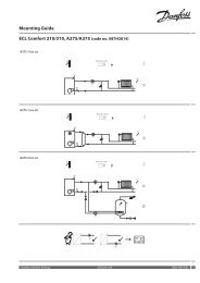
Installation<br />
Mounting the <strong>ECL</strong> <strong>Comfort</strong> <strong>control</strong>ler<br />
For easy access, you should mount the <strong>ECL</strong> <strong>Comfort</strong> <strong>control</strong>ler near the system. Select<br />
one <strong>of</strong> the three following methods:<br />
• Mounting on a wall<br />
• Mounting on a DIN rail<br />
• Mounting in a panel<br />
Screws and rawlplugs are not supplied.<br />
Mounting on a wall<br />
Mount the <strong>control</strong>ler on a wall with a smooth surface and establish the electrical<br />
connections.<br />
Mounting on a DIN rail<br />
Mount the <strong>control</strong>ler on the DIN rail and establish the electrical connections.<br />
Mounting in a panel<br />
Mounting kit: Order code no. 087B1249.<br />
The panel plate thickness must not exceed 5 mm. Prepare a cut-out with the dimensions<br />
93 x 139 mm. Insert the <strong>control</strong>ler into the panel cut-out and fix it with the clamp which<br />
is placed horisontally on the <strong>control</strong>ler. Establish the electrical connections.<br />
For further details on mounting, see the mounting guide.<br />
24 VI.KT.F1.02 © Danfoss 05/2007 DH-SMT/DK<br />
Danfoss<br />
87B787.10<br />
Danfoss<br />
87B788.10<br />
Danfoss<br />
87B789.10<br />
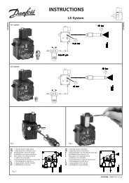
Electrical connections - 230 V a.c. - in general<br />
* Optional connections for safety thermostat<br />
Terminal Description Max. load<br />
20 Supply voltage 230 V a.c. - neutral (N)<br />
21 Supply voltage 230 V a.c. - live (L)<br />
22 Optional connections for safety thermostat<br />
23 Optional connections for safety thermostat<br />
24 M1 Actuator - open 15 VA<br />
25 M1 Actuator - close 15 VA<br />
26 M1 Actuator - neutral<br />
27 P1 Circulation pump - neutral<br />
28 P1 Circulation pump - live (relay R1) 4 (2) A<br />
29 Not to be used<br />
30 Not to be used<br />
Wire cross section: 0.5 - 1.5 mm 2<br />
Incorrect connection can damage the TRIAC outputs.<br />
DH-SMT/DK VI.KT.F1.02 © Danfoss 05/2007 25
Electrical connections - 24 V a.c. - in general<br />
* Optional connections for safety thermostat<br />
Terminal Description Max. load<br />
20 Supply voltage 24 V a.c. - A1<br />
21 Supply voltage 24 V a.c. - A2<br />
22 Optional connections for safety thermostat<br />
23 Optional connections for safety thermostat<br />
24 M1 Actuator - open 15 VA<br />
25 M1 Actuator - close 15 VA<br />
26 M1 Actuator - A1<br />
27 Not to be used<br />
28 Not to be used<br />
29 P1 Phase for circulation pump (relay R2)<br />
30 P1 Relay R2 4 (2) A<br />
Wire cross section: 0.5 - 1.5 mm 2<br />
Incorrect connection can damage the TRIAC outputs.<br />
26 VI.KT.F1.02 © Danfoss 05/2007 DH-SMT/DK<br />
Connecting the <strong>temperature</strong> sensors and the <strong>ECL</strong> BUS<br />
Terminal Description Type (recomm.)<br />
1 and 2 Not to be used<br />
3 and 4 S3 Flow <strong>temperature</strong> sensor ESM-11 / ESMC / ESMU<br />
5 and 6 S4 Return <strong>temperature</strong> sensor ESM-11 / ESMC / ESMU<br />
7 Not to be used<br />
8 and 9 <strong>ECL</strong> BUS, connections for room panel /<br />
remote <strong>control</strong><br />
10 Not to be used<br />
11 and 12 Ext. override<br />
Wire cross section for sensor connections:<br />
0.4 - 0.75 mm 2<br />
Total cable length: Max. 125 m (all sensors incl. the <strong>ECL</strong> BUS)<br />
Cable lengths <strong>of</strong> more than 125 m may cause noise sensibility (EMC).<br />
ECA 60 / 62<br />
ECA 61 / 63<br />
DH-SMT/DK VI.KT.F1.02 © Danfoss 05/2007 27
How to identify your system type<br />
The <strong>ECL</strong> <strong>Comfort</strong> <strong>control</strong>ler is a universal <strong>control</strong>ler that can be used for various systems.<br />
Based on the shown standard systems, it is possible to configure additional systems.<br />
In this section you find the most frequently used systems. If your system is not quite as<br />
shown below, find the diagram which has the best resemblance with your system and<br />
make your own combinations.<br />
Heating system 1:<br />
<strong>Constant</strong> DHW <strong>temperature</strong> <strong>control</strong> with heat exchanger<br />
Heating system 2:<br />
<strong>Constant</strong> <strong>temperature</strong> <strong>control</strong> <strong>of</strong> the DHW circuit with storage tank with built-in<br />
heating coil<br />
28 VI.KT.F1.02 © Danfoss 05/2007 DH-SMT/DK<br />
Adapting the <strong>ECL</strong> <strong>Comfort</strong> <strong>110</strong> <strong>control</strong>ler<br />
When you switch on the <strong>control</strong>ler the first time, it will ask you to choose language<br />
(default language is English).<br />
<br />
<br />
Choose your language.<br />
Accept and go to the next menu.<br />
When the language is chosen, the <strong>control</strong>ler will ask for date and time setting.<br />
<br />
<br />
Set day (dd), month (mm), year (yy), hour (hh), and minuts (mm).<br />
Use the minus and plus buttons to change values and the arrow buttons to shift<br />
between the settings.<br />
Accept the chosen time and date.<br />
When the language has been chosen, and date and time have been set, the <strong>control</strong>ler<br />
will ask for application type.<br />
<br />
<br />
Choose application type.<br />
2 sec.<br />
Start the chosen application.<br />
Go to the ‘Maintenance’ part for further setup <strong>of</strong> your <strong>control</strong>ler.<br />
DH-SMT/DK VI.KT.F1.02 © Danfoss 05/2007 29
Manual <strong>control</strong><br />
Select <strong>control</strong> mode.<br />
<br />
<br />
5 sec.<br />
Go to manual mode.<br />
Actuator M1 is opening ( )<br />
<br />
Actuator M1 is closing ( ) <br />
Pump P1 is ON ( )<br />
<br />
Pump P1 is OFF ( ) <br />
Select <strong>control</strong> mode.<br />
<br />
<br />
Manual mode should only be used for maintenance purposes. In manual mode all <strong>control</strong><br />
and safety functions are deactivated!<br />
30 VI.KT.F1.02 © Danfoss 05/2007 DH-SMT/DK<br />
Placing the <strong>temperature</strong> sensors<br />
It is important that the sensors are mounted in the correct position in your system.<br />
The <strong>temperature</strong> sensor mentioned below are sensors used for the <strong>ECL</strong> <strong>Comfort</strong> series<br />
which not all will be needed for your application!<br />
Outdoor <strong>temperature</strong> sensor (ESMT)<br />
The outdoor sensor should be mounted on that side <strong>of</strong> the building where it is less<br />
likely to be exposed to direct sunshine. It should not be placed close to doors, windows<br />
or air outlets.<br />
Flow <strong>temperature</strong> sensor (ESMU, ESM-11 or ESMC)<br />
Place the sensor max. 15 cm from the mixing point. In systems with heat exchanger,<br />
Danfoss recommends that the ESMU-type to be inserted into the exchanger flow outlet.<br />
Make sure that the surface <strong>of</strong> the pipe is clean and even where the sensor is mounted.<br />
Return <strong>temperature</strong> sensor (ESMU, ESM-11 or ESMC)<br />
The return sensor should always be placed in / on a pipe with return water flow.<br />
Room <strong>temperature</strong> sensor (ESM-10, ECA 60 / 62 room panel or ECA 61 / 63 remote<br />
<strong>control</strong>)<br />
Place the room sensor in the room where the <strong>temperature</strong> is to be <strong>control</strong>led. Do not<br />
place it on outer walls or close to radiators, windows or doors.<br />
DHW <strong>temperature</strong> sensor (ESMU or ESMB-12)<br />
Place the DHW <strong>temperature</strong> sensor according to the manufacturer’s specification.<br />
Boiler <strong>temperature</strong> sensor (ESMU, ESM-11 or ESMC)<br />
Place the sensor according to the boiler manufacturer’s specification.<br />
Flow / air duct <strong>temperature</strong> sensor (ESM-11, ESMB-12, ESMC or ESMU types)<br />
Place the sensor so that it measures a representative <strong>temperature</strong>.<br />
Surface <strong>temperature</strong> sensor (ESMB-12)<br />
Place the sensor in the surface <strong>of</strong> the floor.<br />
Valid for ESM-11: Do not move the sensor after it has been fastened in order to avoid damage<br />
to the sensor element.<br />
DH-SMT/DK VI.KT.F1.02 © Danfoss 05/2007 31
Checklist, electrical connections<br />
Is the <strong>ECL</strong> <strong>Comfort</strong> <strong>control</strong>ler ready for use?<br />
<br />
Make sure that the correct power supply is connected to terminals 21 (Live)<br />
and 20 (Neutral).<br />
Check that the required <strong>control</strong>led units (actuator, pump etc.) are connected<br />
to the correct terminals.<br />
Check that all sensors are connected to the correct terminals.<br />
Switch on the power.<br />
Choose manual operation as <strong>control</strong>ler mode.<br />
Check that valves open and close, and that required <strong>control</strong>led units (pump<br />
etc.) start and stop when operated manually.<br />
Check that the <strong>temperature</strong>s shown in the display match the actual sensors.<br />
32 VI.KT.F1.02 © Danfoss 05/2007 DH-SMT/DK<br />
Frequently asked questions<br />
The time shown in the display is one hour <strong>of</strong>f?<br />
See the daylight saving time changeover in line 7198.<br />
The time shown in the display is not correct?<br />
The internal clock may have been reset, if there has been a power break for more than 36<br />
hours. Set time and date. See line 1000.<br />
What does the symbol mean?<br />
The flow <strong>temperature</strong> is under influence <strong>of</strong> room <strong>temperature</strong> limitation, return<br />
<strong>temperature</strong> limitation, boost, ramping, heating cut-out, DHW priority etc.<br />
The DHW <strong>temperature</strong> is too high during setback periods?<br />
Make sure that the min. flow <strong>temperature</strong> limitation is not too high. See line 2177.<br />
The <strong>temperature</strong> is unstable?<br />
• Check that the flow <strong>temperature</strong> sensor is correctly connected and in the right place.<br />
• If the <strong>control</strong>ler has a room <strong>temperature</strong> signal (line 3000), check that the Gain is not<br />
too high.<br />
• Adjust the <strong>control</strong> parameters (line 6000).<br />
The <strong>control</strong>ler does not operate and the <strong>control</strong> valve is closed?<br />
• Check that the flow <strong>temperature</strong> sensor is measuring the correct value, see ‘Daily use’.<br />
• Check the influence from other measured <strong>temperature</strong>s ( ).<br />
How to restore the factory settings?<br />
See line 7600.<br />
What does P and PI <strong>control</strong> mean?<br />
P <strong>control</strong>: Proportional <strong>control</strong>.<br />
By using a P <strong>control</strong>, the <strong>control</strong>ler will change the flow <strong>temperature</strong> proportional to the<br />
difference between a desired and an actual <strong>temperature</strong>, e.g. a room <strong>temperature</strong>.<br />
A P <strong>control</strong> will always have an <strong>of</strong>fset which not will disappear over time.<br />
PI <strong>control</strong>: Proportional and Integrating <strong>control</strong>.<br />
A PI <strong>control</strong> does the same as a P <strong>control</strong>, but the <strong>of</strong>fset will disappear over time.<br />
A long ‘Intgr. time’ will give a slow but stable <strong>control</strong>, and a short ‘Intgr. time’ will result<br />
in a fast <strong>control</strong> but with a higher risk <strong>of</strong> oscillations.<br />
DH-SMT/DK VI.KT.F1.02 © Danfoss 05/2007 33
Definitions<br />
<strong>Comfort</strong> operation<br />
Normal <strong>temperature</strong> in the system <strong>control</strong>led by the schedule. During heating the flow<br />
<strong>temperature</strong> in the system is higher to maintain the desired room <strong>temperature</strong>. During<br />
cooling the flow <strong>temperature</strong> in the system is lower to maintain the desired room<br />
<strong>temperature</strong>.<br />
<strong>Comfort</strong> <strong>temperature</strong><br />
Temperature maintained in the heating / DHW circuit during comfort periods.<br />
Desired flow <strong>temperature</strong><br />
Temperature calculated by the <strong>control</strong>ler on basis <strong>of</strong> the outdoor <strong>temperature</strong> and<br />
influences from the room and / or return <strong>temperature</strong>s. This <strong>temperature</strong> is used as a<br />
reference for the <strong>control</strong>.<br />
Desired room <strong>temperature</strong><br />
Temperature which is set as the desired room <strong>temperature</strong>. The <strong>temperature</strong> can only be<br />
<strong>control</strong>led by the <strong>ECL</strong> <strong>Comfort</strong> <strong>control</strong>ler if a room <strong>temperature</strong> sensor is installed.<br />
If a sensor is not installed, the set desired room <strong>temperature</strong> however still influences the<br />
flow <strong>temperature</strong>.<br />
In both cases the room <strong>temperature</strong> in each room is typically <strong>control</strong>led by radiator<br />
thermostats / valves.<br />
Desired <strong>temperature</strong><br />
Temperature based on a setting or a <strong>control</strong>ler calculation.<br />
DHW circuit<br />
The circuit for heating the domestic hot water (DHW).<br />
Factory settings<br />
Settings stored in the <strong>control</strong>ler to simplify the setup <strong>of</strong> your <strong>control</strong>ler the first time.<br />
Flow / DHW <strong>temperature</strong><br />
Temperature measured in the flow at any time.<br />
Heating circuit<br />
The circuit for heating the room / building.<br />
Heat curve<br />
A curve showing the relationship between actual outdoor <strong>temperature</strong> and required<br />
flow <strong>temperature</strong>.<br />
Humidity, relative<br />
This value (stated in %) refers to the indoor moisture content compared to the max.<br />
moisture content. The relative humidity is measured by the ECA 62 / 63.<br />
34 VI.KT.F1.02 © Danfoss 05/2007 DH-SMT/DK<br />
Limitation <strong>temperature</strong><br />
Temperature that influences the desired flow / balance <strong>temperature</strong>.<br />
Pt 1000 sensor<br />
All sensors used with the <strong>ECL</strong> <strong>Comfort</strong> <strong>control</strong>ler are based on the Pt 1000 type. The<br />
resistance is 1000 ohm at 0 °C and it changes with approx. 3.9 ohm / degree.<br />
Optimization<br />
The <strong>control</strong>ler optimizes the start / stop time <strong>of</strong> the scheduled <strong>temperature</strong> periods.<br />
Based on the outdoor <strong>temperature</strong>, the <strong>control</strong>ler automatically calculates when to start<br />
/ stop in order to reach the comfort <strong>temperature</strong> at the set time. The lower the outdoor<br />
<strong>temperature</strong>, the earlier the start time. During optimization the comfort / setback<br />
symbol will blink.<br />
Return <strong>temperature</strong><br />
The <strong>temperature</strong> measured in the return can influence the desired flow <strong>temperature</strong>.<br />
Room <strong>temperature</strong> sensor<br />
Temperature sensor placed in the room (reference room, typically the living room)<br />
where the <strong>temperature</strong> is to be <strong>control</strong>led.<br />
Room <strong>temperature</strong><br />
Temperature measured by the room <strong>temperature</strong> sensor, room panel or remote<br />
<strong>control</strong>. The room <strong>temperature</strong> can only be <strong>control</strong>led directly if a room <strong>temperature</strong> is<br />
measured. The room <strong>temperature</strong> can influence the desired flow <strong>temperature</strong>.<br />
Schedule<br />
Schedule for periods with comfort and setback <strong>temperature</strong>s. The schedule can be made<br />
individually for each week day and it consists <strong>of</strong> 2 comfort periods per day.<br />
Setback <strong>temperature</strong><br />
Temperature maintained in the heating / DHW circuit during setback <strong>temperature</strong><br />
periods.<br />
Time bar<br />
The time bars illustrate scheduled periods with comfort <strong>temperature</strong>.<br />
Weather compensation<br />
Flow <strong>temperature</strong> <strong>control</strong> based on the outdoor <strong>temperature</strong>. The <strong>control</strong> is related to a<br />
user-defined heat curve.<br />
The definitions apply to the <strong>Comfort</strong> <strong>110</strong> series. Consequently, you might come across<br />
expressions that are not mentioned in your guide.<br />
DH-SMT/DK VI.KT.F1.02 © Danfoss 05/2007 35
Disposal Instruction<br />
Equipment containing electrical components shall not be disposed together with<br />
domestic waste.<br />
It must be collected separately with other electrical and electronic waste according to<br />
local legislation.<br />
DH-SMT/DK VI.KT.F1.02 © Danfoss 05/2007<br />
*087R9780*<br />
*VIKTF102*<br />
Danfoss can accept no responsibility for possible errors in catalogues, brochures and other printed material. Danfoss reserves the right to alter its products without notice. This also applies to products<br />
already on order provided that such alterations can be made without subsequential changes being necessary in specifications already agreed.<br />
All trademarks in this material are property <strong>of</strong> the respective companies. Danfoss and the Danfoss logotype are trademarks <strong>of</strong> Danfoss A/S. All rights reserved.<br />
37 VI.KT.F1.02 © Danfoss 05/2007 DH-SMT/DK<br />
✐