2U PSU
2U PSU
2U PSU

You also want an ePaper? Increase the reach of your titles
YUMPU automatically turns print PDFs into web optimized ePapers that Google loves.
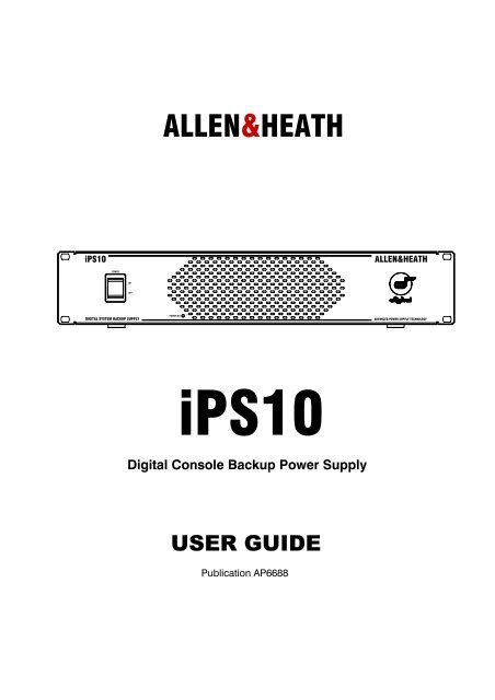
ALLEN&HEATH<br />
iPS10 ALLEN&HEATH<br />
POWER<br />
ON<br />
OFF<br />
DIGITAL SYSTEM BACKUP SUPPLY<br />
POWER ON<br />
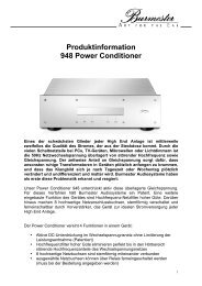
iPS10<br />
Digital Console Backup Power Supply<br />
USER GUIDE<br />
Publication AP6688<br />
ADVANCED POWER SUPPLY TECHNOLOGY
Limited Two Year Warranty<br />
This product has been manufactured in the UK by ALLEN & HEATH and<br />
is warranted to be free from defects in materials or workmanship for a<br />
period of two years from the date of purchase by the original owner.<br />
To ensure a high level of performance and reliability for which this<br />
equipment has been designed and manufactured, read this User Guide<br />
before operating.<br />
In the event of a failure, notify and return the defective unit to ALLEN &<br />
HEATH or its authorised agent as soon as possible for repair under<br />
warranty subject to the following conditions:<br />
Conditions Of Warranty<br />
1. The equipment has been installed and operated in accordance with<br />
the instructions in this User Guide<br />
2. The equipment has not been subject to misuse either intended or<br />
accidental, neglect, or alteration other than as described in the User<br />
Guide or Service Manual, or approved by ALLEN & HEATH.<br />
3. Any necessary adjustment, alteration or repair has been carried out<br />
by ALLEN & HEATH or its authorised agent.<br />
4. The defective unit is to be returned carriage prepaid to ALLEN &<br />
HEATH or its authorised agent with proof of purchase.<br />
5. Units returned should be packed to avoid transit damage.<br />
In certain territories the terms may vary. Check with your ALLEN &<br />
HEATH agent for any additional warranty, which may apply.<br />
This product complies with the European Electromagnetic<br />
Compatibility directives 89/336/EEC & 92/31/EEC and the<br />
European Low Voltage Directives 73/23/EEC & 93/68/EEC.<br />
Any changes or modifications to the power supply unit not approved<br />
by Allen & Heath could void the compliance of the product and<br />
therefore the users authority to operate it.<br />
iPS10 User Guide AP6688 Issue 1.<br />
Copyright © 2007 Allen & Heath. All rights reserved<br />
Manufactured in the United Kingdom by Allen & Heath Limited<br />
Kernick Industrial Estate, Penryn, Cornwall, TR10 9LU, UK<br />
http://www.allen-heath.com<br />
2 iPS10 User Guide
Important Safety Instructions<br />
WARNINGS - Read the following before proceeding :<br />
CAUTION<br />
ATTENTION: RISQUE DE CHOC ELECTRIQUE – NE PAS OUVRIR<br />
Read instructions: Retain these safety and operating instructions for future reference. Adhere to<br />
all warnings printed here and on the power supply unit. Follow the operating<br />
instructions printed in this User Guide.<br />
Do not remove covers: Operate the power supply unit with its covers correctly fitted. Refer any<br />
service work on the power supply unit to competent technical personnel only.<br />
Power sources: Connect the power supply unit to a mains power supply only of the type<br />
described in this User Guide and marked on the rear panel. Use only the<br />
power cord with sealed mains plug appropriate for your local mains supply<br />
as provided with the power supply unit. If the provided plug does not fit into<br />
your outlet consult your service agent for assistance.<br />
Power cord routing: Route the power cord so that it is not likely to be walked on, stretched or<br />
pinched by items placed upon or against it.<br />
Grounding: Do not defeat the grounding and polarisation means of the power cord plug.<br />
Do not remove or tamper with the ground connection in the power cord.<br />
WARNING: This equipment must be earthed.<br />
Water and moisture: To reduce the risk of fire or electric shock do not expose the power supply<br />
unit to rain or moisture or use it in damp or wet conditions. Do not place<br />
containers of liquid on it which might spill into any openings.<br />
Ventilation: Do not obstruct the ventilation slots or position the power supply unit where<br />
the air flow required for ventilation is impeded. If the power supply unit is to<br />
be operated in a flightcase ensure that it is constructed to allow adequate<br />
ventilation.<br />
Heat and vibration: Do not locate the power supply unit in a place subject to excessive heat or<br />
direct sunlight as this could be a fire hazard. Locate the power supply unit<br />
away from any equipment which produces heat or causes excessive<br />
vibration.<br />
Servicing: Switch off the equipment and unplug the power cord immediately if it is<br />
exposed to moisture, spilled liquid, objects fallen into the openings, the<br />
power cord or plug become damaged, during lightening storms, or if smoke,<br />
odour or noise is noticed. Refer servicing to qualified technical personnel<br />
only.<br />
Installation: Install the power supply unit in accordance with the instructions printed in this<br />
User Guide. Do not connect the output of power supply unit to any other<br />
equipment other than that specified by Allen & Heath.<br />
iPS10 User Guide 3
Precautions<br />
Important Mains plug wiring instructions.<br />
The power supply unit is supplied with a moulded mains plug fitted to<br />
the AC mains power lead. Follow the instructions below if the mains<br />
plug has to be replaced.<br />
The wires in the mains lead are coloured in accordance with the<br />
following code:<br />
TERMINAL<br />
WIRE COLOUR<br />
European USA/Canada<br />
L LIVE BROWN BLACK<br />
N NEUTRAL BLUE WHITE<br />
E EARTH GND GREEN & YELLOW GREEN<br />
The wire which is coloured Green and Yellow must be connected to<br />
the terminal in the plug which is marked with the letter E or with the<br />
Earth symbol. This appliance must be earthed.<br />
The wire which is coloured Blue must be connected to the terminal in<br />
the plug which is marked with the letter N.<br />
The wire which is coloured Brown must be connected to the terminal<br />
in the plug which is marked with the letter L.<br />
Ensure that these colour codes are followed carefully in the event of<br />
the plug being changed.<br />
Damage : To prevent damage to the power supply unit cosmetics, avoid placing<br />
heavy objects on the unit, scratching the surface with sharp objects,<br />
or subjecting the power supply unit to rough handling and vibration.<br />
Environment : Protect from excessive dirt, dust, heat and vibration when operating<br />
and storing. Avoid tobacco ash, smoke, drinks spillage, and<br />
exposure to rain and moisture. If the power supply unit becomes wet,<br />
switch off and remove power immediately. Allow to dry out<br />
thoroughly before using again.<br />
Cleaning : Avoid the use of chemicals, abrasives or solvents. The power supply<br />
unit is best cleaned with a soft brush and dry lint-free cloth. If the<br />
ventilation grilles become blocked with dust use a vacuum cleaner to<br />
suck the dirt out. Do not remove the cover to clean the unit.<br />
Transporting : The power supply unit should be transported in the original packing<br />
or purpose built flightcase to protect it from damage during transit.<br />
DC power cable: Plan the location of the mixing console and power supply unit so that<br />
the DC power and CAT5 cables are not fully extended. Full extension<br />
of the cable can stress the mixing console and power supply unit<br />
connectors and may result in undesired performance. Ensure that<br />
the power cable is located such that it cannot be stood on or tripped<br />
over.<br />
4 iPS10 User Guide
Introduction<br />
This user guide presents a quick reference to the iPS10 digital console power supply<br />
unit. We recommend that you read this fully before starting. Included is information on<br />
installing, connecting and operating the power supply unit along with panel drawings<br />
and technical specification. Whilst we believe the information in this guide to be reliable<br />
we do not assume responsibility for inaccuracies. We also reserve the right to make<br />
changes in the interest of further product development.<br />
We are able to offer further product support through our worldwide network of approved<br />
dealers and service agents. You can also access our Web site (www.allen-heath.com)<br />
for information on our company and its pedigree, our full product range and our design<br />
philosophy. To help us provide the most efficient service please keep a record of your<br />
power supply unit serial number, and date and place of purchase to be quoted in any<br />
communication regarding this product. The serial number is located on the rear panel.<br />
Check the Packing Contents<br />
Retain the product packing should you need to ship the product in future. You should find the<br />
following components:<br />
iPS10 ALLEN&HEATH<br />
POWER<br />
120 USA, 220<br />
ON<br />
OFF<br />
DIGITAL SYSTEM BACKUP SUPPLY<br />
POWER ON<br />
ADVANCED POWER SUPPLY TECHNOLOGY<br />
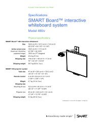
1x iPS10 POWER SUPPLY UNIT. This is packed with its<br />
rubber feet fitted. The feet can be removed for rack<br />
mounting.<br />
1x IEC MAINS LEAD with moulded plug. Check that the<br />
plug is suitable for connection to your local mains<br />
supply.<br />
iPS10/n<br />
Where n = mains voltage 120 (USA), 220 (EU), 240 (UK)<br />
1x DC POWER CABLE 2.8m male>female 10-pin.<br />
Part number 003-576. Connects the iPS10 power rails<br />
to the iLive Surface or iDR0 MiniRack backup supply<br />
input.<br />
1x CAT5 CABLE 2.8m RJ45 connections.<br />
Part number AH6831. Connects the iPS10 to the iLive<br />
Surface or iDR0 MiniRack backup temperature monitor<br />
input.<br />
DOCUMENTATION including the User Guide AP6688,<br />
Safety Sheet AP3345, and the Registration Card<br />
AP3594.<br />
iPS10 User Guide 5
The iPS10 Power Supply<br />
The slimline, <strong>2U</strong> rack mountable iPS10 power supply unit is a high performance, low noise, universal<br />
mains voltage, switched mode power supply producing the DC voltages required to run the iLive<br />
Surface or IDR0 MiniRack. It is available as an option to provide redundant backup of the internal<br />
mains power supplies fitted in these iLive components. The iLive will operate with either or both<br />
supplies switched on.<br />
Two connecting cables are required between the iPS10 and iLive. The power unit produces 5<br />
different DC voltages and has three independent ground connections. These connect to the iLive via<br />
a 2.8 meter long multicore DC cable fitted with 10-pin circular locking connectors. Voltage rail<br />
protection, thermal sensing and fan cooling ensure the power supply unit will operate consistently.<br />
The power unit temperature information connects to the iLive via a 2.8 meter long CAT5 cable.<br />
Current status may be viewed by the operator on the iLive Surface TouchScreen.<br />
Installation<br />
Free standing<br />
The iPS10 can be operated as a freestanding unit for shelf or floor operation. Check that its plastic<br />
feet are fitted. Ensure adequate air flow around the unit. It must not be covered in any way. Always<br />
stand the unit on a firm flat surface away from any soft furnishings or carpet.<br />
Rack mounting<br />
The iPS10 is designed as a 19 inch rack mount unit and will occupy <strong>2U</strong> (3.5 inches) of rack space.<br />
The plastic feet may need to be removed before rack mounting. Retain the feet for future use.<br />
Ensure natural convection of airflow around the unit by allowing good ventilation below, in front of<br />
and behind the unit. Rack equipment known to produce a significant amount of heat should not be<br />
mounted directly below the power supply unit. Forced convection by means of a rack mounted fantray<br />
may be desirable in situations where space is restricted and the ambient air temperature is high.<br />
Cables<br />
The DC power and temperature monitor cables are 2.8 meters long to allow the unit to be positioned<br />
away from the console. Make sure the cables are not stretched in any way and are routed to avoid<br />
becoming kinked or damaged. Allow enough service loop for access and removal of the unit.<br />
Ensure all connectors are fully plugged in and locked.<br />
Consideration should be given to the earthing (grounding) arrangement of the system. The iLive<br />
chassis is connected to the mains earth via the power supply unit. Do not remove the IEC power<br />
cord earth connection. A screw terminal chassis grounding post is provided on the rear of the iPS10<br />
for situations where additional earth bonding is required.<br />
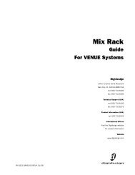
Dimensions<br />
88 mm / 3.46"<br />
<strong>2U</strong><br />
482 mm / 19"<br />
443 mm / 17.4"<br />
374 mm / 14.7"<br />
310 mm / 12.2"<br />
Do not obstruct the ventilation<br />
slots. Ensure adequate air flow around<br />
the iPS10.<br />
Ensure proper grounding. Do not<br />
remove the IEC mains cord earth<br />
(ground) connection.<br />
Do not remove the cover of the<br />
iPS10. There are no user serviceable<br />
parts inside.<br />
6 iPS10 User Guide
Controls and Connections<br />
iPS10 ALLEN&HEATH<br />
POWER<br />
ON<br />
OFF<br />
DIGITAL SYSTEM BACKUP SUPPLY<br />
POWER ON/OFF<br />
POWER ON<br />
Press to switch the iPS10<br />
power unit on or off. The<br />
internal fan runs at<br />
constant speed while the<br />
unit is switched on.<br />
DC POWER OUT<br />
10-pin female socket to output the<br />
5 DC voltage rails and 3 ground<br />
connections. It also has two pins<br />
for power status information. Plug<br />
in the DC power cable supplied<br />
with the unit. Do this by rotating<br />
the male plug until the mating tabs<br />
align with the socket, then insert<br />
fully and tighten the locking screw<br />
ring. Be careful not to cross<br />
thread the screw ring.<br />
ALLEN&HEATH iPS10 BACKUP <strong>PSU</strong><br />
CONNECT ONLY TO<br />
SPECIFIED A&H<br />
DIGITAL EQUIPMENT<br />
TEMPERATURE MONITOR<br />
RJ45 socket to output the temperature<br />
status information to the iLive. Use the<br />
CAT5 cable supplied with the unit. A<br />
sensor monitors the temperature<br />
inside the unit. The supply shuts down<br />
safely if the internal temperature<br />
reaches 85 degrees C. A fan inside<br />
the unit prevents it running too hot.<br />
POWER STATUS<br />
Made in the UK by ALLEN&HEATH LIMITED<br />
ADVANCED POWER SUPPLY TECHNOLOGY<br />
The blue indicator lights at full brightness while the unit is<br />
switched on and working correctly. If the indicator does<br />
not light check that mains power is switched on and the<br />
IEC mains cord properly inserted. If the indicator lights<br />
at half brightness there may be a voltage rail fault. If this<br />
is the case switch the unit off and contact your Allen &<br />
Heath service agent.<br />
GROUND POST<br />
Chassis metal grounding<br />
(earthing) post for attaching<br />
a grounding wire to other<br />
equipment or metal cases or<br />
racks in the system if<br />
needed. For best results<br />
use heavy duty wire. Note<br />
that the iPS10 metalwork is<br />
grounded via the mains<br />
cord. Do not defeat this<br />
connection.<br />
iPS10 User Guide 7<br />
SERIAL NUMBER<br />
MAINS FUSE<br />
MAINS INPUT<br />
Plug in the IEC<br />
mains cord supplied<br />
with the unit. Make<br />
sure it is inserted<br />
fully and has not<br />
been modified in<br />
any way.<br />
DO NOT OBSTRUCT VENTILATION OPENINGS.<br />
DO NOT OPEN. NO USER SERVICEABLE PARTS INSIDE.<br />
THIS APPARATUS MUST BE EARTHED BY THE POWER CORD.<br />
WARNING: TO REDUCE THE RISK OF ELECTRIC SHOCK<br />
DO NOT EXPOSE THIS APPARATUS TO RAIN OR MOISTURE.<br />
AVIS: RISQUE DE CHOC ELECTRIQUE - NE PAS OUVRIR.<br />
This device complies with Part 15 of the FCC Rules. Operation is subject to the following two conditions:<br />
(1) this device may not cause harmful interference, and<br />
(2) this device must accept any interference received, including interference that may cause undesired operation.<br />
CAUTION: FOR CONTINUED PROTECTION AGAINST RISK OF FIRE REPLACE FUSE<br />
WITH SAME TYPE AND RATING. DISCONNECT SUPPLY BEFORE CHANGING FUSE.<br />
ATTENTION: REMPLACER PAR UN FUSIBLE STRICTEMENT IDENTIQUE EN VALEURS.<br />
COUPER L'ALIMENTATION AVANT DE CHANGER LE FUSIBLE.<br />
CHASSIS<br />
GROUND<br />
MAINS INPUT<br />
100 - 240V~<br />
47-63Hz ~ 320W MAX<br />
FUSE<br />
T5AL 250V<br />
20MM<br />
To check or replace the fuse use a flat bladed<br />
screwdriver or coin to push in and rotate the<br />
fuse holder until it pops out. Always replace<br />
with the correct type and value (T5AL 20mm<br />
250V). In the event of repeated failure of the<br />
mains fuse, consult your Allen & Heath service<br />
agent.
Connecting the iPS10 to the iLive Surface<br />
iLIVE SURFACE<br />
INTERNAL <strong>PSU</strong><br />
Cable retention clip<br />
IEC MAINS CABLES<br />
Mains power 100 - 240V AC<br />
Surface CPU power on<br />
Internal <strong>PSU</strong> on<br />
Backup <strong>PSU</strong> on<br />
DC CABLE<br />
10way<br />
TEMPERATURE MONITOR CABLE<br />
CAT5<br />
Connecting the iPS10 to the iDR0 MiniRack<br />
INTERNAL <strong>PSU</strong><br />
IEC MAINS CABLES<br />
MAINS<br />
Mains power 100 - 240V AC<br />
Female plug<br />
Male plug<br />
iDR0 MINIRACK<br />
Female plug<br />
TEMPERATURE MONITOR CABLE<br />
DC CABLE CAT5<br />
10way<br />
Male plug<br />
iPS10 BACKUP <strong>PSU</strong><br />
iPS10 BACKUP <strong>PSU</strong><br />
MAINS<br />
MAINS<br />
8 iPS10 User Guide
Notes on Operating the iPS10<br />
The iPS10 is intended as a backup power supply for iLive system<br />
components. At the time of release of this user guide it can be used<br />
with any of the 4 surfaces (iLive-80, iLive-112, iLive-144 and iLive-<br />
176) and the iDR0 DSP MiniRack. These components can operate<br />
using their internal mains power units only. Connecting the iPS10 in<br />
addition to the internal supply provides dual supply redundancy. The<br />
component can be operated with either or both supplies switched<br />
on. It continues to operate without interruption if either supply is<br />
switched off or loses power.<br />
The iPS10 features a universal mains voltage input that can accept<br />
any AC mains voltage between 100 and 240V AC. We recommend<br />
that it is run on the same power distribution that feeds the iLive unit<br />
being connected to. For protection against temporary loss of mains<br />
power an external UPS (uninterruptible power supply) could be used.<br />
Make sure the iPS10 and the iLive unit being connected to are both<br />
turned off before plugging or unplugging the mains and DC POWER<br />
cables.<br />
Blue LED indicators on the CPU module at the rear of the iLive<br />
surface light to indicate that the power supplies are switched on and<br />
working correctly. There is one for the internal surface supply and<br />
one for the backup supply. The iPS10 sends power good/fail status<br />
signals to the iLive via its 10way DC cable.<br />
The iPS10 front panel blue POWER ON indicator lights at full<br />
brightness to indicate normal operation. If a voltage rail fault is<br />
detected then it reduces to half brightness. If this happens, switch<br />
the unit off and contact your Allen & Heath service agent.<br />
The iPS10 has an internal fan to assist cooling and ventilation. The<br />
fan runs at constant speed. Thermal protection is provided to safely<br />
shut down the power rails if the unit reaches 85 degrees C internally.<br />
If this happens check that the fan is running, the ventilation slots are<br />
not blocked and there is adequate airflow around the unit. Switch the<br />
unit off and allow it to cool. When it has cooled sufficiently it<br />
automatically resets and resumes operation.<br />
The CAT5 cable provided with the unit is used to send the<br />
temperature status to the iLive. The current temperature measured<br />
within the iPS10 is displayed on the iLive Surface TouchScreen<br />
Utility/Diagnostics/Temperature Display page. The minimum and<br />
maximum temperatures reached are also displayed. These values<br />
can be reset.<br />
iPS10 User Guide 9
Technical specification<br />
Technology Switched mode with power factor correction<br />
Mains input IEC connector<br />
Mains voltage 85 to 250V AC, 47 to 63 Hz ~<br />
Power consumption 320W max<br />
Mains fuse T5AL 250V 20mm.<br />
DC voltage rails +8, +18, -18, +24, +57 V DC<br />
DC output 10-pin female circular chassis mounted socket<br />
Temperature sense RJ45 connector<br />
DC cable 2.8m multicore male to female. A&H part number 003-576<br />
Temperature cable 2.8m CAT5 RJ45. A&H part number AH6831<br />
Protection Under voltage detection and thermal sensing<br />
Cooling Fan assisted. Thermal shutdown at 85 degrees C<br />
Installation <strong>2U</strong> rack mount (integral ears) or free standing (plastic feet fitted)<br />
Dimensions Rack mounted 482 x 310 x 88mm (<strong>2U</strong>) 19” x 12.2” x 3.46”<br />
Free standing 482 x 310 x 92mm (including feet) 19” x12.2” x 3.6”<br />
Minimum clearance at rear for connectors 64mm (2.5”) min<br />
Packed 580 x 510 x 210mm 22.9” x 20” x 8.3”<br />
Weight Unpacked 7 kg (15.4 lbs)<br />
Packed 8.5 kg (18.7 lbs)<br />
88 mm / 3.46"<br />
<strong>2U</strong><br />
482 mm / 19"<br />
443 mm / 17.4"<br />
374 mm / 14.7"<br />
310 mm / 12.2"<br />
10 iPS10 User Guide