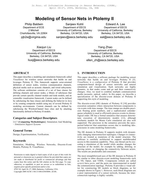
Modeling of Sensor Nets in Ptolemy II
Modeling of Sensor Nets in Ptolemy II
Modeling of Sensor Nets in Ptolemy II

You also want an ePaper? Increase the reach of your titles
YUMPU automatically turns print PDFs into web optimized ePapers that Google loves.
Philip Baldw<strong>in</strong><br />
Department <strong>of</strong> ECE<br />
2 Mitchell<br />
Charlottesville, VA 22904<br />
pjb2e@virg<strong>in</strong>ia.edu<br />
ABSTRACT<br />
<strong>Model<strong>in</strong>g</strong> <strong>of</strong> <strong>Sensor</strong> <strong>Nets</strong> <strong>in</strong> <strong>Ptolemy</strong> <strong>II</strong><br />
Xiaojun Liu<br />
Department <strong>of</strong> EECS<br />
University <strong>of</strong> California, Berkeley<br />
Berkeley, CA 94720, USA<br />
liuxj@eecs.berkeley.edu<br />
This paper describes a model<strong>in</strong>g and simulation framework called<br />
VisualSense for wireless sensor networks that builds on and<br />
leverages <strong>Ptolemy</strong> <strong>II</strong>. This framework supports actor-oriented<br />
def<strong>in</strong>ition <strong>of</strong> sensor nodes, wireless communication channels,<br />
physical media such as acoustic channels, and wired subsystems.<br />
The s<strong>of</strong>tware architecture consists <strong>of</strong> a set <strong>of</strong> base classes for<br />
def<strong>in</strong><strong>in</strong>g channels and sensor nodes, a library <strong>of</strong> subclasses that<br />
provide certa<strong>in</strong> specific channel models and node models, and an<br />
extensible visualization framework. Custom nodes can be def<strong>in</strong>ed<br />
by subclass<strong>in</strong>g the base classes and def<strong>in</strong><strong>in</strong>g the behavior <strong>in</strong> Java<br />
or by creat<strong>in</strong>g composite models us<strong>in</strong>g any <strong>of</strong> several <strong>Ptolemy</strong> <strong>II</strong><br />
model<strong>in</strong>g environments. Custom channels can be def<strong>in</strong>ed by<br />
subclass<strong>in</strong>g the WirelessChannel base class and by attach<strong>in</strong>g<br />
functionality def<strong>in</strong>ed <strong>in</strong> <strong>Ptolemy</strong> <strong>II</strong> models.<br />
Categories and Subject Descriptors<br />
I.6.7 [Comput<strong>in</strong>g Methodologies]: Simulation And <strong>Model<strong>in</strong>g</strong><br />
– Simulation Support Systems<br />
General Terms<br />
Design, Experimentation, Verification.<br />
Keywords<br />
In Proc. <strong>of</strong> Information Process<strong>in</strong>g <strong>in</strong> <strong>Sensor</strong> Networks, (IPSN),<br />
April 26-27, 2004, Berkeley, CA, USA<br />
Simulation, <strong>Model<strong>in</strong>g</strong>, Wireless Networks, Discrete-Event<br />
Models, <strong>Ptolemy</strong> <strong>II</strong>, VisualSense.<br />
Permission to make digital or hard copies <strong>of</strong> all or part <strong>of</strong> this work for<br />
personal or classroom use is granted without fee provided that copies are<br />
not made or distributed for pr<strong>of</strong>it or commercial advantage and that<br />
copies bear this notice and the full citation on the first page. To copy<br />
otherwise, or republish, to post on servers or to redistribute to lists,<br />
requires prior specific permission and/or a fee.<br />
IPSN’04, April 26–27, 2004, Berkeley, California, USA.<br />
Copyright 2004 ACM 1-58113-846-6/04/0004...$5.00..<br />
Sanjeev Kohli<br />
Department <strong>of</strong> EECS<br />
University <strong>of</strong> California, Berkeley<br />
Berkeley, CA 94720, USA<br />
sanjeev@eecs.berkeley.edu<br />
Edward A. Lee<br />
Department <strong>of</strong> EECS<br />
University <strong>of</strong> California, Berkeley<br />
Berkeley, CA 94720, USA<br />
eal@eecs.berkeley.edu<br />
Yang Zhao<br />
Department <strong>of</strong> EECS<br />
University <strong>of</strong> California, Berkeley<br />
Berkeley, CA 94720, USA<br />
ellen_zh@eecs.berkeley.edu<br />
1. INTRODUCTION<br />
This paper describes a s<strong>of</strong>tware package for model<strong>in</strong>g sensor<br />
networks that builds on and leverages <strong>Ptolemy</strong> <strong>II</strong> [5].<br />
VisualSense is a configuration <strong>of</strong> <strong>Ptolemy</strong> <strong>II</strong> that provides<br />
component-based design <strong>of</strong> sensor networks and natural<br />
simulation and visualization. Such networks are highly<br />
dynamic, <strong>in</strong> that nodes come and go and their connectivity<br />
changes. Also, we need to comb<strong>in</strong>e multiple communication<br />
media (acoustic, optical, radio). In this paper, we describe a<br />
specialization <strong>of</strong> the discrete-event doma<strong>in</strong> <strong>of</strong> <strong>Ptolemy</strong> <strong>II</strong><br />
support<strong>in</strong>g this style <strong>of</strong> model<strong>in</strong>g.<br />
The discrete-event (DE) doma<strong>in</strong> <strong>of</strong> <strong>Ptolemy</strong> <strong>II</strong> [10] provides<br />
execution semantics where <strong>in</strong>teraction between components is<br />
via events with time stamps. The time stamps are double-precision<br />
float<strong>in</strong>g po<strong>in</strong>t numbers, and a sophisticated calendarqueue<br />
scheduler is used to efficiently process events <strong>in</strong> chronological<br />
order. DE has a formal semantics that ensures determ<strong>in</strong>ate<br />
execution <strong>of</strong> determ<strong>in</strong>istic models [12], although<br />
stochastic models for Monte Carlo simulation are also well<br />
supported. The precision <strong>in</strong> the semantics prevents the unexpected<br />
behavior that sometimes occurs due to model<strong>in</strong>g idiosyncrasies<br />
<strong>in</strong> some model<strong>in</strong>g frameworks.<br />
The DE doma<strong>in</strong> <strong>in</strong> <strong>Ptolemy</strong> <strong>II</strong> supports models with dynamically<br />
chang<strong>in</strong>g <strong>in</strong>terconnection topologies. Changes <strong>in</strong> connectivity<br />
are treated as mutations <strong>of</strong> the model structure. The<br />
s<strong>of</strong>tware is carefully architected to support multithreaded<br />
access to this mutation capability. Thus, one thread can be execut<strong>in</strong>g<br />
a simulation <strong>of</strong> the model while another changes the<br />
structure <strong>of</strong> the model, for example by add<strong>in</strong>g, delet<strong>in</strong>g, or<br />
mov<strong>in</strong>g actors, or chang<strong>in</strong>g the connectivity between actors.<br />
The results are predictable and consistent.<br />
The most straightforward uses <strong>of</strong> the DE doma<strong>in</strong> <strong>in</strong> <strong>Ptolemy</strong> <strong>II</strong><br />
are similar to other discrete-event model<strong>in</strong>g frameworks such<br />
as NS, Opnet, and VHDL. Components (which are called<br />
actors) have ports, and the ports are <strong>in</strong>terconnected to model<br />
the communication topology. <strong>Ptolemy</strong> <strong>II</strong> provides a visual editor<br />
for construct<strong>in</strong>g DE models as block diagrams, as for<br />
example shown <strong>in</strong> Figure 1. However, such block diagrams are<br />
a poor representation <strong>of</strong> a sensor network, because the <strong>in</strong>terconnection<br />
topology is highly variable.
This paper describes a subclass <strong>of</strong> the DE model<strong>in</strong>g framework<br />
<strong>in</strong> <strong>Ptolemy</strong> <strong>II</strong> that is specifically <strong>in</strong>tended to model sensor networks.<br />
It largely preserves DE semantics, but changes the<br />
mechanism for connect<strong>in</strong>g components. In particular, it<br />
removes the need for explicit connections between ports, and<br />
<strong>in</strong>stead associates ports with channels by name (e.g. “Radio-<br />
Channel”). Connectivity can then be determ<strong>in</strong>ed on the basis <strong>of</strong><br />
the physical locations <strong>of</strong> the components. The algorithm for<br />
determ<strong>in</strong><strong>in</strong>g connectivity is itself encapsulated <strong>in</strong> a component<br />
as a channel model, and hence can be developed by the model<br />
builder.<br />
Figure 1. Typical DE model <strong>in</strong> <strong>Ptolemy</strong>, represented as a block diagram.<br />
Such block diagram representations are not well-suited to sensor network model<strong>in</strong>g.<br />
Figure 2. Example <strong>of</strong> a sensor node def<strong>in</strong>ed as a composite actor<br />
us<strong>in</strong>g a block diagram <strong>in</strong> the <strong>Ptolemy</strong> <strong>II</strong> discrete-event doma<strong>in</strong>.<br />
<strong>Sensor</strong> nodes themselves can be modeled <strong>in</strong> Java, or more<br />
<strong>in</strong>terest<strong>in</strong>gly, us<strong>in</strong>g more conventional DE models (as block<br />
diagrams) or other <strong>Ptolemy</strong> <strong>II</strong> models (such as dataflow models,<br />
f<strong>in</strong>ite-state mach<strong>in</strong>es or cont<strong>in</strong>uous-time models). For<br />
example, a sensor node with modal behavior can be def<strong>in</strong>ed by<br />
sketch<strong>in</strong>g a f<strong>in</strong>ite-state mach<strong>in</strong>e and provid<strong>in</strong>g ref<strong>in</strong>ements to<br />
each <strong>of</strong> the states to def<strong>in</strong>e the behavior <strong>of</strong> the node <strong>in</strong> that<br />
state. This can be used, for example, to model energy consumption<br />
as a function <strong>of</strong> state, enabl<strong>in</strong>g potential representation<br />
<strong>of</strong> sensor nodes us<strong>in</strong>g resource <strong>in</strong>terfaces [3].<br />
Sophisticated models <strong>of</strong> the coupl<strong>in</strong>g between energy consumption<br />
and media access control protocols become possible.<br />
1.1 Related Work<br />
A number <strong>of</strong> frameworks for<br />
model<strong>in</strong>g wireless systems are<br />
available.<br />
Ns-2[15] is a well-established,<br />
open-source network simulator<br />
with many contributors at<br />
several <strong>in</strong>stitutions <strong>in</strong>clud<strong>in</strong>g<br />
LBL, Xerox PARC, UCB, and<br />
USC/ISI. It is a discrete event<br />
simulator with extensive<br />
support for simulat<strong>in</strong>g TCP/IP,<br />
rout<strong>in</strong>g, and multicast<br />
protocols over wired and<br />
wireless (local and satellite)<br />
networks. The wireless and<br />
mobility support <strong>in</strong> ns-2 comes<br />
from the Monarch project at<br />
CMU [14], which provides<br />
channel models and wireless<br />
network layer components <strong>in</strong><br />
the physical, l<strong>in</strong>k, and rout<strong>in</strong>g<br />
layers. It provides a radio<br />
propagation model based on<br />
the two ray ground reflection<br />
approximation and a shared<br />
media model <strong>in</strong> the physical<br />
layer; it implements the<br />
IEEE802.11 MAC protocol <strong>in</strong><br />
the l<strong>in</strong>k layer; it implements<br />
the dynamic source rout<strong>in</strong>g<br />
protocol, etc. <strong>in</strong> the rout<strong>in</strong>g<br />
layer.<br />
<strong>Sensor</strong>Sim[17], from UCLA,<br />
also builds on ns-2 and claims<br />
power models and sensor channel<br />
models. A power model<br />
consists <strong>of</strong> an energy provider<br />
(the battery) and a set <strong>of</strong><br />
energy consumers (CPU, radio,<br />
and sensors). An energy consumer<br />
can have several modes,<br />
each correspond<strong>in</strong>g to a different<br />
trade-<strong>of</strong>f between performance<br />
and power. For<br />
example, the radio may have a<br />
number <strong>of</strong> transmit modes<br />
us<strong>in</strong>g different symbol rates<br />
and transmit power. The sensor<br />
channels model the dynamic<br />
<strong>in</strong>teraction between the physi-
cal environment and the sensor nodes. <strong>Sensor</strong>Sim also claims<br />
hybrid simulation <strong>in</strong> which real sensor nodes can participate.<br />
Unfortunately, at the time <strong>of</strong> this writ<strong>in</strong>g, <strong>Sensor</strong>Sim has not<br />
been publicly released and does not appear to be under further<br />
development.<br />
EmStar [6], a more recent project from UCLA, focuses on the<br />
problem <strong>of</strong> develop<strong>in</strong>g s<strong>of</strong>tware for wireless sensor networks.<br />
Its execution environment supports simulation, deployment,<br />
and a hybrid mode that comb<strong>in</strong>es simulation with real wireless<br />
communication among sensors situated <strong>in</strong> the environment.<br />
Services provided or planned by EmStar <strong>in</strong>clude network<strong>in</strong>g<br />
and time synchronization. In the programm<strong>in</strong>g model <strong>of</strong><br />
EmStar, modules run with<strong>in</strong> <strong>in</strong>dividual L<strong>in</strong>ux processes that<br />
communicate through message pass<strong>in</strong>g via device files.<br />
OPNET Modeler [16] is a commercial tool from OPNET Technologies,<br />
Inc., which has been engaged <strong>in</strong> network s<strong>of</strong>tware<br />
and applications s<strong>in</strong>ce 1986. It <strong>of</strong>fers sophisticated model<strong>in</strong>g<br />
and simulation <strong>of</strong> communication networks. An OPNET model<br />
is hierarchical, where the top level conta<strong>in</strong>s the communication<br />
nodes and the topology <strong>of</strong> the network. Each node can be constructed<br />
from s<strong>of</strong>tware components, called processes, <strong>in</strong> a<br />
block-diagram fashion, and each process can be constructed<br />
us<strong>in</strong>g f<strong>in</strong>ite state mach<strong>in</strong>e (FSM) models. It uses a discrete<br />
event simulator to execute the entire model. In conventional<br />
OPNET models, nodes are connected by static l<strong>in</strong>ks. The<br />
OPNET Wireless Module provides support for wireless and<br />
mobile communications. It uses a 13 stage “transceiver pipel<strong>in</strong>e”<br />
to dynamically determ<strong>in</strong>e the connectivity and propaga-<br />
Attribute<br />
«Interface»<br />
Executable<br />
Director<br />
0..n<br />
«Interface»<br />
Actor<br />
0..1<br />
0..1<br />
ComponentEntity<br />
TypedAtomicActor<br />
NamedObj<br />
conta<strong>in</strong>er<br />
0..1<br />
0..n<br />
CompositeEntity<br />
0..n 0..1<br />
TypedCompositeActor<br />
Figure 3. UML class diagram show<strong>in</strong>g key classes <strong>in</strong> <strong>Ptolemy</strong> <strong>II</strong>, on which VisualSense is built.<br />
0..n<br />
0..1<br />
0..1 conta<strong>in</strong>er<br />
conta<strong>in</strong>er<br />
conta<strong>in</strong>er<br />
0..1<br />
tion effects among nodes. Users can specify transceiver<br />
frequency, bandwidth, power, and other characteristics. These<br />
characteristics are used by the transceiver pipel<strong>in</strong>e stages to<br />
calculate the average power level <strong>of</strong> the received signals to<br />
determ<strong>in</strong>e whether the receiver can receive this signal. In addition,<br />
antenna ga<strong>in</strong> patterns and terra<strong>in</strong> models are well supported.<br />
OMNET++[19] is an open source tool for discrete-event model<strong>in</strong>g.<br />
With the Mobility Framework extension[13], it shares<br />
many concepts, solutions and features with OPNET. But<br />
<strong>in</strong>stead <strong>of</strong> us<strong>in</strong>g FSM models for processes, it def<strong>in</strong>es a component<br />
<strong>in</strong>terface for the basic module, with a set <strong>of</strong> methods<br />
<strong>in</strong>clud<strong>in</strong>g <strong>in</strong>itialize(), handleMessage(), and f<strong>in</strong>ish(), that are<br />
overridden by the model builder. The <strong>in</strong>itialize() method is<br />
called by the simulator at the beg<strong>in</strong>n<strong>in</strong>g <strong>of</strong> execut<strong>in</strong>g the network,<br />
the handleMessage() method is called when a message is<br />
sent to this module, and the f<strong>in</strong>ish() method is called when the<br />
execution is prepared to stop. This object-oriented approach is<br />
similar to the abstract semantics <strong>of</strong> <strong>Ptolemy</strong> <strong>II</strong> [5].<br />
J-Sim [18] is built on object-oriented component pr<strong>in</strong>ciples.<br />
INET, a generalized packet switched network model, is implemented<br />
<strong>in</strong> J-Sim, together with a suite <strong>of</strong> Internet best effort,<br />
<strong>in</strong>tegrated services, and differentiated services protocols.<br />
All <strong>of</strong> these systems provide extension po<strong>in</strong>ts where modelbuilders<br />
can def<strong>in</strong>e functionality by add<strong>in</strong>g code. Some are<br />
also open-source s<strong>of</strong>tware, like VisualSense. All except<br />
EmStar provide some form <strong>of</strong> discrete-event simulation, but<br />
none provide the ability that VisualSense <strong>in</strong>herits from<br />
<strong>Ptolemy</strong> <strong>II</strong> to <strong>in</strong>tegrate<br />
diverse models <strong>of</strong> computation,<br />
such as cont<strong>in</strong>uoustime,<br />
dataflow, synchronous/reactive,<br />
and timetriggered.<br />
This capability<br />
can be used, for example,<br />
to model the physical<br />
dynamics <strong>of</strong> mobility <strong>of</strong><br />
0..n l<strong>in</strong>k<br />
sensor nodes, their digital<br />
l<strong>in</strong>k 0..n<br />
circuits, energy consumption<br />
and production, signal<br />
process<strong>in</strong>g, or real-time<br />
s<strong>of</strong>tware behavior. Such<br />
models would have to be<br />
0..n<br />
built with low-level code.<br />
<strong>Ptolemy</strong> <strong>II</strong> supports hierar-<br />
ComponentRelation<br />
chical nest<strong>in</strong>g <strong>of</strong> heterogeneous<br />
models <strong>of</strong><br />
computation [5]. It also<br />
appears to be unique<br />
among these model<strong>in</strong>g<br />
environments <strong>in</strong> that FSM<br />
models can be arbitrarily<br />
nested with other models;<br />
i.e., they are not restricted<br />
to be leaf nodes [8]. It also<br />
appears to be the only one<br />
to provide a modern type<br />
system at the actor level<br />
(vs. the code level) [20]<br />
and to type check communication<br />
packet structure<br />
(us<strong>in</strong>g record types).<br />
Port Relation
1.2 Paper Overview<br />
Section 2 describes how to build models. Section 3 gives the<br />
s<strong>of</strong>tware architecture <strong>of</strong> VisualSense, with emphasis on customization<br />
mechanisms. Examples <strong>of</strong> models us<strong>in</strong>g the framework<br />
are described <strong>in</strong> Section 6.<br />
2. BUILDING MODELS<br />
VisualSense is constructed by subclass<strong>in</strong>g key classes <strong>in</strong><br />
<strong>Ptolemy</strong> <strong>II</strong>. The extension to <strong>Ptolemy</strong> consists <strong>of</strong> a few new<br />
Java classes and some XML files. The classes are designed to<br />
be subclassed by model builders for customization, although<br />
non-trivial models can also be constructed without writ<strong>in</strong>g any<br />
Java code. In the latter case, sensor network nodes are specified<br />
us<strong>in</strong>g block diagrams and f<strong>in</strong>ite state mach<strong>in</strong>es.<br />
An example <strong>of</strong> a sensor node def<strong>in</strong>ed as a composite actor is<br />
shown <strong>in</strong> Figure 2. At the top <strong>of</strong> the figure is a segment <strong>of</strong> a<br />
wireless model show<strong>in</strong>g a “WirelessDirector” (which specifies<br />
that the diagram is a wireless model), a channel def<strong>in</strong>ition<br />
named “radio” (with the lightn<strong>in</strong>g bolt icon), and a sensor node<br />
named “WirelessComposite.” The sensor node has two ports<br />
named “radioIn” and “radioOut.” The parameter screen for the<br />
radioIn port is shown at the right, where you can see that the<br />
outsideChannel parameter is set to “radio,” which <strong>in</strong>dicates<br />
that communication is via the channel named “radio.”<br />
The composite conta<strong>in</strong>s the model shown at the bottom <strong>of</strong> Figure<br />
2. This model gives the behavior <strong>of</strong> the sensor node. It is<br />
not a wireless model, but is rather an ord<strong>in</strong>ary discrete-event<br />
<strong>Ptolemy</strong> <strong>II</strong> model, like that <strong>of</strong> Figure 1, where communication<br />
is represented explicitly by l<strong>in</strong>es <strong>in</strong> the block diagram. That it<br />
is a discrete-event model is specified by the “DEDirector”<br />
component. But a different model <strong>of</strong> computation could be<br />
used at this level as well. The parameter screen at the right <strong>in</strong><br />
the figure shows that noth<strong>in</strong>g is given for an <strong>in</strong>sideChannel,<br />
which is another <strong>in</strong>dication that at this lower level <strong>of</strong> the hierarchy,<br />
communication is not wireless.<br />
The behavior <strong>of</strong> the sensor node example <strong>in</strong> Figure 2 is readily<br />
understood from the diagram. When a radio signal is received,<br />
it generates a random number accord<strong>in</strong>g to a Rayleigh distribution,<br />
and then retransmits the same radio signal after a time<br />
delay given by that random number. Although this rather simplistic<br />
behavior does not constitute a useful sensor node, it is<br />
easy to imag<strong>in</strong>e significant elaborations that leverage the considerable<br />
model<strong>in</strong>g expressiveness <strong>of</strong> <strong>Ptolemy</strong> <strong>II</strong> to describe<br />
much more complex behavior.<br />
3. SOFTWARE ARCHITECTURE<br />
The key classes <strong>in</strong> <strong>Ptolemy</strong> <strong>II</strong> (which def<strong>in</strong>e its meta model)<br />
are shown <strong>in</strong> Figure 3. Executable components implement the<br />
Actor <strong>in</strong>terface, and can be either atomic or composite. Atomic<br />
actors are def<strong>in</strong>ed <strong>in</strong> Java, while composite actors are assemblies<br />
<strong>of</strong> actors and relations. Each actor, whether atomic or not,<br />
conta<strong>in</strong>s ports, which are l<strong>in</strong>ked <strong>in</strong> a composite actor via relations.<br />
A top-level model is itself a composite actor, typically<br />
with no ports. Actors, ports and relations can all have attributes<br />
(parameters). One <strong>of</strong> the attributes is a director. The director<br />
plays a key role <strong>in</strong> <strong>Ptolemy</strong> <strong>II</strong>: it def<strong>in</strong>es the semantics <strong>of</strong> a<br />
composite. It gives the concurrency model and the communication<br />
semantics. In VisualSense, the director implements the<br />
simulator. The WirelessDirector is an almost completely<br />
unmodified subclass <strong>of</strong> the pre-exist<strong>in</strong>g discrete-event director<br />
(DEDirector) <strong>in</strong> <strong>Ptolemy</strong> <strong>II</strong>.<br />
The extensions that constitute VisualSense are shown <strong>in</strong> Figure<br />
4. A node <strong>in</strong> a wireless network is an actor that can be a subclass<br />
<strong>of</strong> either TypedAtomicActor or TypedCompositeActor.<br />
The difference between these is that for TypedAtomicActor,<br />
the behavior is def<strong>in</strong>ed <strong>in</strong> Java code, whereas for TypedCompositeActor,<br />
the behavior is def<strong>in</strong>ed by another <strong>Ptolemy</strong> <strong>II</strong><br />
model, which is itself a composite <strong>of</strong> actors.<br />
Actors that communicate wirelessly have ports that are<br />
<strong>in</strong>stances <strong>of</strong> WirelessIOPort. As with any <strong>Ptolemy</strong> <strong>II</strong> port, the<br />
actor sends data by call<strong>in</strong>g the send or broadcast method on<br />
the port. The send method permits specification <strong>of</strong> a numerically<br />
<strong>in</strong>dexed subchannel, whereas the broadcast method will<br />
send to all subchannels.<br />
In the case <strong>of</strong> WirelessIOPort, send and broadcast cannot<br />
determ<strong>in</strong>e the dest<strong>in</strong>ation ports us<strong>in</strong>g block-diagram-style connectivity<br />
because there is no such connectivity. Instead, they<br />
identify an <strong>in</strong>stance <strong>of</strong> WirelessChannel by name, and delegate<br />
to that <strong>in</strong>stance to determ<strong>in</strong>e the dest<strong>in</strong>ation(s) <strong>of</strong> the messages.<br />
The <strong>in</strong>stance is specified by sett<strong>in</strong>g the outsideChannel parameter<br />
<strong>of</strong> the port equal to the name <strong>of</strong> the wireless channel (all<br />
actors at a given level <strong>of</strong> the hierarchy have unique names, a<br />
feature provided by the base class).<br />
The WirelessChannel <strong>in</strong>terface and the AtomicWirelessChannel<br />
base class, shown <strong>in</strong> Figure 4, are designed for extensibility.<br />
They work together with WirelessIOPort, which uses the<br />
public method, transmit, to send data. That method takes three<br />
arguments, a token1 to transmit, a source port, and a token represent<strong>in</strong>g<br />
transmit properties (transmit power, for example, as<br />
discussed below).<br />
AtomicWirelessChannel has a suite <strong>of</strong> protected methods, <strong>in</strong>dicated<br />
<strong>in</strong> the UML diagram by the lead<strong>in</strong>g pound sign (#); <strong>in</strong> the<br />
<strong>Ptolemy</strong> <strong>II</strong> cod<strong>in</strong>g style, protected methods have names that<br />
beg<strong>in</strong> with lead<strong>in</strong>g underscores(_). These provide simple<br />
default behavior, but are <strong>in</strong>tended to be overridden <strong>in</strong> subclasses<br />
to provide more sophisticated channel models. This is<br />
an example <strong>of</strong> the strategy design pattern [7], where the code<br />
provid<strong>in</strong>g the large-scale behavior delegates to protected methods<br />
for detailed behavior.<br />
The default behavior <strong>of</strong> AtomicWirelessChannel is represented<br />
by the follow<strong>in</strong>g pseudo code:<br />
public void transmit(token, sender, properties) {<br />
foreach receiver <strong>in</strong> range {<br />
_transmitTo(token, sender, receiver, properties)<br />
}<br />
}<br />
To determ<strong>in</strong>e which receivers are <strong>in</strong> range, it calls the protected<br />
method _receiversInRange(), which by default<br />
returns all receivers conta<strong>in</strong>ed by ports that refer to the same<br />
channel name as that specified by the sender. The<br />
_transmitTo() method by default uses the public transformProperties()<br />
method to modify the properties argument<br />
(see below) and then put the token and the modified properties<br />
<strong>in</strong>to the receiver. The transformProperties() method<br />
1<br />
A token <strong>in</strong> <strong>Ptolemy</strong> <strong>II</strong> is a wrapper for data. <strong>Ptolemy</strong> <strong>II</strong> provides a rich set<br />
<strong>of</strong> data types encapsulated as tokens, <strong>in</strong>clud<strong>in</strong>g composite types such as<br />
arrays, matrices, and records (which have named fields). A sophisticated<br />
type system ensures validity <strong>of</strong> data that is exchanged via tokens. A rich<br />
expression language permits def<strong>in</strong>ition <strong>of</strong> tokens as expressions that can<br />
depend on parameters <strong>of</strong> actors or ports. Scop<strong>in</strong>g rules limit the visibility<br />
<strong>of</strong> parameters accord<strong>in</strong>g to the hierarchy <strong>of</strong> the model, thus avoid<strong>in</strong>g the<br />
pitfalls <strong>of</strong> us<strong>in</strong>g global variables. For details, see [9].
«Interface»<br />
Actor<br />
TypedAtomicActor<br />
NodeModels<br />
TypedIOPort<br />
+broadcast(token : Token)<br />
+get(subchannel : <strong>in</strong>t) : Token<br />
+send(subchannel : <strong>in</strong>t, token : Token)<br />
WirelessIOPort<br />
+<strong>in</strong>sideChannel : Str<strong>in</strong>gParameter<br />
+<strong>in</strong>sideTransmitProperties : Parameter<br />
+outsideChannel : Str<strong>in</strong>gParameter<br />
+outsideTransmitProperties : Parameter<br />
+WirelessIOPort(conta<strong>in</strong>er : CompositeEntity, name : Str<strong>in</strong>g)<br />
+broadcast(data : Token)<br />
+getInsideChannel() : WirelessIOChannel<br />
+getOutsideChannel() : WirelessIOChannel<br />
+getProperties(channelIndex : <strong>in</strong>t) : Token<br />
+getPropertiesInside(channelIndex : <strong>in</strong>t) : Token<br />
+send(channel : <strong>in</strong>t, token : Token)<br />
#_<strong>in</strong>sideIsWireless() : boolean<br />
#_outsideIsWireless() : boolean<br />
DEReceiver<br />
+get() : Token<br />
+put(token : Token)<br />
WirelessReceiver<br />
conta<strong>in</strong>ed actors<br />
WirelessComposite<br />
+newPort() : TypedIOPort<br />
-_properties : Token<br />
+WirelessReceiver()<br />
+WirelessReceiver(conta<strong>in</strong>er : IOPort)<br />
+getProperties() : Token<br />
+put(token : Token, properties : Token)<br />
TypedCompositeActor<br />
AtomicWirelessChannel<br />
+defaultProperties : Parameter (record)<br />
+WirelessChannel(conta<strong>in</strong>er : CompositeEntity, name : Str<strong>in</strong>g)<br />
#_distanceBetween(port1 : WirelessIOPort, port2 : WirelessIOPort) : double<br />
conta<strong>in</strong>ed ports#_isInRange(source<br />
: WirelessIOPort, dest<strong>in</strong>ation : WirelessIOPort, properties : RecordToken) : boolean<br />
#_locationOf(port : WirelessIOPort) : double[]<br />
#_receiversInRangeOf(port : WirelessIOPort, properties : RecordToken) : List <strong>of</strong> WirelessReceiver<br />
#_transmitTo(token : Token, sender : WirelessIOPort, receiver : WirelessReceiver, properties : RecordToken)<br />
delegate transmission<br />
put tokens<br />
DelayChannel<br />
+propagationSpeed : Parameter (double)<br />
delegate put and get LimitedRangeChannel<br />
creates<br />
DEDirector<br />
WirelessDirector<br />
«Interface»<br />
PropertyTransformer<br />
+transformProperties(properties : RecordToken, source : WirelessIOPort, dest<strong>in</strong>ation : WirelessIOPort) : RecordToken<br />
«Interface»<br />
WirelessChannel<br />
+getChannelPort() : ChannelPort<br />
+listen<strong>in</strong>gInputPorts() : List<br />
+listen<strong>in</strong>gOutputPorts() : List<br />
+registerPropertyTransformer(transformer : PropertyTransformer, port : WirelessIOPort)<br />
+send<strong>in</strong>gOutputPorts() : List<br />
+send<strong>in</strong>gInputPorts() : List<br />
+transmit(data : Token, source : WirelessIOPort, properties : RecordToken)<br />
+unregisterPropertyTransformer(transfomer : PropertyTransformer, port : WirelessIOPort)<br />
ChannelPort<br />
ErasureChannel<br />
+lossProbability : Parameter (double)<br />
+seed : Parameter (long)<br />
+defaultProperties : Parameter ({range=double})<br />
PowerLossChannel<br />
+efficiency : Parameter (double)<br />
+powerLossFactor : Parameter (double)<br />
+defaultTransmitPower : Parameter (double)<br />
Figure 4. UML class diagram show<strong>in</strong>g the key classes for wireless sensor net model<strong>in</strong>g. These classes plus some XML files specify<strong>in</strong>g<br />
configuration <strong>in</strong>formation and libraries constitute VisualSense.<br />
1..1
applies any property transformers that have registered us<strong>in</strong>g<br />
the registerPropertyTransformer() method, but does<br />
noth<strong>in</strong>g further. Thus, if there are no registered properties<br />
transformers, the default AtomicWirelessChannel has no range<br />
limitations and <strong>in</strong>troduces no transmission degradations. We<br />
can now show through a series <strong>of</strong> examples how subclass<strong>in</strong>g<br />
makes it easy to construct more detailed (and useful) channel<br />
models.<br />
4. MODEL COMPONENTS<br />
We illustrate the contruction <strong>of</strong> model components such as<br />
channel models with examples.<br />
4.1 Erasure Channel<br />
Consider a channel that randomly drops data. This can be<br />
def<strong>in</strong>ed as follows:<br />
public class ErasureChannel extends AtomicWirelessChannel{<br />
... specify constructor ...<br />
public Parameter lossProbability;<br />
public Parameter seed;<br />
private Random _random = new Random();<br />
public void transmit(token, sender, properties) {<br />
double experiment = _random.nextDouble();<br />
if (experiment >= lossProbability.doubleValue()) {<br />
super.transmit(token, sender, properties);<br />
}<br />
}<br />
}<br />
It is that simple. This channel adds to the base class a parameter<br />
called lossProbability. (The details <strong>of</strong> construct<strong>in</strong>g the<br />
channel and this parameter are not shown, see [9]). The Java<br />
class Random is used to “throw the dice” to determ<strong>in</strong>e whether<br />
or not the transmission should actually occur.<br />
Note that the above channel model might not be exactly what<br />
you want. In particular, it throws the dice once, and uses the<br />
result to decide whether or not to transmit to all recipient ports<br />
that are <strong>in</strong> range. A better design might throw the dice once for<br />
each recipient port. We leave it as a (simple) exercise for the<br />
reader to see how to modify the above code to accomplish this.<br />
4.2 Limited Range Channels<br />
The above channels have unlimited range, <strong>in</strong> that any <strong>in</strong>put<br />
port that references the channel by name is <strong>in</strong> range. This is<br />
because the default implementation <strong>of</strong> _isInRange() simply<br />
returns true. It is easy for a subclass to change this behavior.<br />
Consider, for example, a channel model that uses a distance<br />
threshold:<br />
public class LimitedRangeChannel extends ErasureChannel {<br />
... specify constructor ...<br />
public Parameter range;<br />
protected boolean _isInRange(<br />
source, dest<strong>in</strong>ation, properties) {<br />
double distance = _distanceBetween(source, dest<strong>in</strong>ation);<br />
if (distance
WirelessChannel <strong>in</strong>terface has a key method,<br />
registerPropertyTransformer(), which can be used to<br />
register any object that implements the TransformProperties<br />
<strong>in</strong>terface (which <strong>in</strong>cludes any object that implements<br />
WirelessChannel). An object that implements this <strong>in</strong>terface is<br />
given the opportunity to modify the transmit properties <strong>of</strong> any<br />
transmission (or it can selectively <strong>in</strong>dicate an <strong>in</strong>terest only <strong>in</strong><br />
transmissions com<strong>in</strong>g from a particular port).<br />
A transmit antenna model, for example, can be realized by an<br />
object that implements the TransformProperties <strong>in</strong>terface. In<br />
fact, we can use <strong>Ptolemy</strong> <strong>II</strong> <strong>in</strong>frastructure to provide an object<br />
that uses another <strong>Ptolemy</strong> <strong>II</strong> model to implement the property<br />
transformation. Thus, the full suite <strong>of</strong> sophisticated signal process<strong>in</strong>g<br />
capabilities <strong>of</strong> <strong>Ptolemy</strong> <strong>II</strong> are at the disposal <strong>of</strong> the<br />
builder <strong>of</strong> the antenna model.<br />
The same goes for terra<strong>in</strong> models, although there is a caveat.<br />
Property transformers are required to implement modifications<br />
<strong>of</strong> the properties record that are commutative. That is, if there<br />
are several property transformers that can affect a particular<br />
transmission, the result <strong>of</strong> apply<strong>in</strong>g these transformers needs to<br />
be the same regardless <strong>of</strong> the order <strong>in</strong> which they are applied.<br />
For simple terra<strong>in</strong> models that apply only power loss, this will<br />
<strong>of</strong>ten be true. For some more sophisticated terra<strong>in</strong> models,<br />
however, it will not be true. Such models must be implemented<br />
as channels, subclass<strong>in</strong>g for example the PowerLossChannel.<br />
4.5 Delay Channels<br />
The DelayChannel subclass <strong>of</strong> ErasureChannel has a propagationSpeed<br />
parameter that the channel uses to determ<strong>in</strong>e the<br />
delay between transmission and reception <strong>of</strong> a signal. In the<br />
DelayChannel class, when the transmit() method is called,<br />
the channel calculates the delay to the specified location and<br />
requests that the director re-<strong>in</strong>voke it after that delay has<br />
elapsed (by call<strong>in</strong>g the fireAt() method <strong>of</strong> the director,<br />
which places a request on the event queue). When it is reawakened,<br />
it delivers the message to the receiver.<br />
4.6 Message Duration and Collisions<br />
A message duration can be represented by a properties record<br />
with a duration field. We have provided a simple actor that can<br />
be put <strong>in</strong>to a receiver node that uses this field to determ<strong>in</strong>e<br />
whether two messages have collided. It also uses a power field<br />
and checks the ratio <strong>of</strong> received powers aga<strong>in</strong>st an SNRThresholdInDB<br />
parameter. This actor has two outputs, one <strong>of</strong> which<br />
produces a received token whose power to <strong>in</strong>terference ratio<br />
exceeded the specified threshold, and the other <strong>of</strong> which produces<br />
any received tokens that did not meet this threshold.<br />
Thus, it is easy to build a model that monitors collisions, and to<br />
implement retransmission protocols <strong>in</strong> the event <strong>of</strong> collisions.<br />
The f<strong>in</strong>ite state mach<strong>in</strong>e doma<strong>in</strong> <strong>of</strong> <strong>Ptolemy</strong> <strong>II</strong> is particularly<br />
convenient for this.<br />
4.7 Battery Models and Modal Models<br />
<strong>Sensor</strong>s nodes have limited resources and cannot operate for an<br />
<strong>in</strong>f<strong>in</strong>ite amount <strong>of</strong> time. Predict<strong>in</strong>g sensor node failures is<br />
important <strong>in</strong> creat<strong>in</strong>g a network model. Some factors that can<br />
cause a network failure are battery power, geographical<br />
changes that can cause sensor nodes to go out <strong>of</strong> range, signal<br />
strength, and process<strong>in</strong>g problems. Models <strong>of</strong> the state <strong>of</strong> a<br />
node can be constructed us<strong>in</strong>g the facilities <strong>of</strong> <strong>Ptolemy</strong> <strong>II</strong>,<br />
<strong>in</strong>clud<strong>in</strong>g f<strong>in</strong>ite state mach<strong>in</strong>es to represent the state <strong>of</strong> the<br />
node and numerical models <strong>of</strong> battery life or energy scaveng<strong>in</strong>g.<br />
5. FRAMEWORK INFRASTRUCTURE<br />
The <strong>Ptolemy</strong> <strong>II</strong> framework provides some useful <strong>in</strong>frastructure.<br />
5.1 Hierarchy and Heterogeneity<br />
<strong>Ptolemy</strong> <strong>II</strong> supports hierarchical mix<strong>in</strong>g <strong>of</strong> dist<strong>in</strong>ct models <strong>of</strong><br />
computation. The example <strong>in</strong> Figure 2 h<strong>in</strong>ts at this capability,<br />
s<strong>in</strong>ce the <strong>in</strong>side model and the outside model have dist<strong>in</strong>ct<br />
directors. In this case, both directors implement discrete-event<br />
semantics, with only small differences. However, it is possible<br />
to have much bigger differences. It is also not uncommon for<br />
the director <strong>in</strong>side to be an <strong>in</strong>stance <strong>of</strong> the same class as the<br />
director outside. This permits a certa<strong>in</strong> modularity <strong>in</strong> design.<br />
In order to support this, the WirelessIOPort class <strong>in</strong> Figure 4<br />
can optionally specify both an <strong>in</strong>sideChannel and an outsideChannel.<br />
If the outside channel is specified, then wireless<br />
communication is used on the outside. If the <strong>in</strong>side channel is<br />
specified, then wireless communication is used on the <strong>in</strong>side.<br />
Both can be used at the same time.<br />
Another useful comb<strong>in</strong>ation uses the cont<strong>in</strong>uous-time doma<strong>in</strong><br />
<strong>of</strong> <strong>Ptolemy</strong> <strong>II</strong>. This doma<strong>in</strong> <strong>in</strong>cludes a CTDirector with a<br />
sophisticated numerical solver for ord<strong>in</strong>ary differential equations<br />
and extensive support for hybrid systems model<strong>in</strong>g [2].<br />
This can be used, for example, to construct sophisticated models<br />
<strong>of</strong> the physical mobility <strong>of</strong> mobile sensor platforms.<br />
5.2 Visualization<br />
<strong>Ptolemy</strong> <strong>II</strong> permits customized icons for components <strong>in</strong> a<br />
model. This can be used to render as part <strong>of</strong> a model useful<br />
visualizations that lend <strong>in</strong>sight <strong>in</strong>to the behavior <strong>of</strong> models. For<br />
example, a sensor node can have as an icon a translucent circle<br />
that represents (roughly or exactly) its transmit range. Examples<br />
that use this visualization capability are described <strong>in</strong> section<br />
6.<br />
5.3 Type System<br />
<strong>Ptolemy</strong> <strong>II</strong> <strong>in</strong>cludes a sophisticated type system [20]. In this<br />
type system, actors, parameters, and ports can all impose constra<strong>in</strong>ts<br />
on types, and a type resolution algorithm identifies the<br />
most specific types that satisfy all the constra<strong>in</strong>ts. By default,<br />
the type system <strong>in</strong> <strong>Ptolemy</strong> <strong>II</strong> <strong>in</strong>cludes a type constra<strong>in</strong>t for<br />
each connection <strong>in</strong> a block diagram. However, <strong>in</strong> wireless<br />
models, these connections do not represent all the type constra<strong>in</strong>ts.<br />
In particular, every actor that sends data to a wireless<br />
channel requires that every recipient from that channel be able<br />
to accept that data type. VisualSense imposes this constra<strong>in</strong>t <strong>in</strong><br />
the WirelessChannel base class, so unless a particular model<br />
builder needs more sophisticated constra<strong>in</strong>ts, the model builder<br />
does not need to specify particular data types <strong>in</strong> the model.<br />
They will be <strong>in</strong>ferred from the ultimate sources <strong>of</strong> the data and<br />
propagated throughout the model.<br />
Note, however, that it would be unwise to explicitly model<br />
type constra<strong>in</strong>ts between every transmitter and every receiver<br />
us<strong>in</strong>g a channel. If there are n such users, this would be n 2 constra<strong>in</strong>ts,<br />
which for large n could bog down type resolution. As<br />
shown <strong>in</strong> Figure 4, a channel conta<strong>in</strong>s a s<strong>in</strong>gle port, an <strong>in</strong>stance<br />
<strong>of</strong> ChannelPort. This is used to set up n type constra<strong>in</strong>ts, one to<br />
each user <strong>of</strong> the channel. This simplifies type resolution and
keeps the static analysis <strong>of</strong> the model tractable even for large<br />
models.<br />
6. APPLICATIONS<br />
Although our experiments are still prelim<strong>in</strong>ary, we have constructed<br />
some non-trivial examples to illustrate the use <strong>of</strong> the<br />
<strong>in</strong>frastructure described here. We cannot describe them all<br />
here, but these are illustrative <strong>of</strong> the capabilities.<br />
6.1 Flood<strong>in</strong>g<br />
First, [4] describes an evaluation <strong>of</strong> an algorithm for efficiently<br />
broadcast<strong>in</strong>g queries <strong>in</strong> a sensor network. To reach all nodes,<br />
when a sensor receives a radio message, it may repeat the message.<br />
The objective is to reduce the number <strong>of</strong> such repetitions<br />
required to permeate the network. A screen image <strong>of</strong> one <strong>of</strong> the<br />
experiments performed is shown <strong>in</strong> Figure 5. In that image,<br />
each circle represents a sensor node. At the center <strong>of</strong> the circle<br />
is an icon for an antenna. This represents the location <strong>of</strong> the<br />
transmitter and receiver for the node. The sensor nodes are randomly<br />
scattered (an actor is provided <strong>in</strong> the library to realize<br />
the random scatter).<br />
An execution <strong>of</strong> this model propagates a fixed number <strong>of</strong> queries,<br />
specified as a model parameter, through the sensor network.<br />
In this experiment, the base node, shown with a green<br />
translucent circle <strong>in</strong> Figure 5, broadcasts a query periodically.<br />
Initially all nodes repeat this query upon hear<strong>in</strong>g it. However,<br />
as the execution proceeds, the nodes learn about the network<br />
topology around them, and based on the distributed algorithm<br />
described <strong>in</strong> [4], decide to cont<strong>in</strong>ue repeat<strong>in</strong>g or to stop repeat<strong>in</strong>g.<br />
The nodes with red icons <strong>in</strong> Figure 5 are those that repeat,<br />
while the nodes with blue icons do not repeat, after the algorithm<br />
has converged.<br />
In this experiment, the sensor nodes communicate via a radio<br />
channel with no time delay and no noise or losses. The broadcast<br />
range <strong>of</strong> a sensor node is a parameter <strong>of</strong> the node, and is<br />
<strong>in</strong>dicated by the circular icon. In Figure 5, it is identical for all<br />
nodes; however, it can easily be varied. A more sophisticated<br />
channel model can be used by simply dropp<strong>in</strong>g it <strong>in</strong>to this<br />
model and renam<strong>in</strong>g it to match the channel name specified by<br />
the nodes.<br />
6.2 Triangulation<br />
The second experiment, described <strong>in</strong> [1], is shown <strong>in</strong> Figure 6.<br />
In this experiment, a model <strong>of</strong> the power source (batteries, <strong>in</strong><br />
this case) <strong>of</strong> sensor nodes is coupled with a model <strong>of</strong> a scenario<br />
where acoustic sensors cooperate to determ<strong>in</strong>e the location <strong>of</strong> a<br />
sound source by triangulation.<br />
As <strong>in</strong> the <strong>Sensor</strong>Sim simulator [17], multiple channels can be<br />
used <strong>in</strong> the same model <strong>in</strong> VisualSense. In this second experiment,<br />
an acoustic channel carries signals from a mobile sound<br />
source, and sensor nodes communicate via a radio channel.<br />
The acoustic channel <strong>in</strong>cludes propagation delay, while the<br />
Figure 5. A screen image <strong>of</strong> a model described <strong>in</strong> [4] that is used to evaluate a flood<strong>in</strong>g communication optimization<br />
heuristic.
adio channel is modeled as <strong>in</strong>stantaneous, similar to the model<br />
<strong>in</strong> the flood<strong>in</strong>g experiment described above. As with that<br />
experiment, the circular icons <strong>of</strong> the nodes represent their<br />
transmit range.<br />
The acoustic channel carries signals from a mobile sound<br />
source to the sensor nodes. When a sensor node detects an<br />
acoustic signal, it broadcasts the observation (the time <strong>of</strong> the<br />
detection and the location <strong>of</strong> the sensor node) via the radio<br />
channel. A sound tracker actor collects the observations and<br />
computes the time and location <strong>of</strong> sound emissions from the<br />
mobile source.<br />
6.3 Traffic Monitor<strong>in</strong>g<br />
Most sensor networks are highly dynamic. Objects monitored<br />
by a sensor network come and go, and may move around <strong>in</strong> the<br />
sensor field. New sensor nodes can jo<strong>in</strong> the network, and when<br />
the battery <strong>of</strong> a sensor node is depleted, it leaves the network.<br />
A natural model <strong>of</strong> such dynamic sensor networks must support<br />
changes not only to the <strong>in</strong>terconnection topology, but also<br />
to the set <strong>of</strong> components present <strong>in</strong> a network. As mentioned<br />
before, <strong>Ptolemy</strong> <strong>II</strong> has support for mutations <strong>of</strong> the model<br />
structure. We illustrate how this can be leveraged <strong>in</strong> sensor<br />
network model<strong>in</strong>g with a traffic monitor<strong>in</strong>g application.<br />
sensor node,<br />
sends radio signal<br />
sound source<br />
sensor detected a<br />
sound<br />
triangulation node<br />
<strong>Sensor</strong>s are distributed on a stretch <strong>of</strong> road to collect traffic<br />
<strong>in</strong>formation that is sent to a base station for further analysis.<br />
To model and simulate such a network, we first construct a<br />
model for the sensor field, which <strong>in</strong>cludes a component for<br />
each sensor node and the channels (a wireless channel for communication<br />
between sensors, and an acoustic channel for the<br />
signal propagation from the pass<strong>in</strong>g vehicles to the sensors).<br />
In order to simulate the behavior <strong>of</strong> the network, we also need<br />
a stimulus model to generate traffic <strong>in</strong>puts to the sensor field.<br />
The question is what k<strong>in</strong>d <strong>of</strong> <strong>in</strong>puts the stimulus model should<br />
provide to the sensor field model. Intuitively it is a car that<br />
enters the stretch <strong>of</strong> road on one boundary. In this sense, the<br />
stimulus is actually a car model added to the sensor field. S<strong>in</strong>ce<br />
cars can enter the area at any time and then leave after a while,<br />
it is not feasible to <strong>in</strong>clude them statically <strong>in</strong> the sensor field<br />
model.<br />
To capture the dynamic structure due to cars enter<strong>in</strong>g or leav<strong>in</strong>g,<br />
we use a higher order actor (one that takes as <strong>in</strong>put another<br />
model). Such an actor conta<strong>in</strong>s another model that specifies its<br />
computation, and dur<strong>in</strong>g execution, the conta<strong>in</strong>ed model can be<br />
dynamically changed. The higher-order actor has two <strong>in</strong>puts,<br />
with the first <strong>in</strong>put receiv<strong>in</strong>g data that the conta<strong>in</strong>ed model<br />
should process, and the second <strong>in</strong>put receiv<strong>in</strong>g model changes<br />
to the current conta<strong>in</strong>ed model. The model changes can <strong>in</strong>clude<br />
Figure 6. Example <strong>of</strong> a <strong>Ptolemy</strong> <strong>II</strong> model from [1] show<strong>in</strong>g a sound source that moves as the model executes, four sensors<br />
that detect the sound and communicate via radio, and a sound tracker that receives the radio signals and uses<br />
triangulation to identify the location <strong>of</strong> the sound source.
add<strong>in</strong>g new components such as actors that model cars, remov<strong>in</strong>g<br />
exist<strong>in</strong>g components, and add<strong>in</strong>g or remov<strong>in</strong>g connections.<br />
When execution beg<strong>in</strong>s, the higher-order actor conta<strong>in</strong>s an<br />
empty model <strong>in</strong>side. It first receives a model change for construct<strong>in</strong>g<br />
the sensor field. After the change is applied, the execution<br />
cont<strong>in</strong>ues with no vehicles <strong>in</strong> the sensor field. When the<br />
traffic model decides that there is a car enter<strong>in</strong>g the field, it<br />
generates a car model and sends it to the higher-order actor,<br />
which then changes the conta<strong>in</strong>ed model to <strong>in</strong>clude the car<br />
model. Execution cont<strong>in</strong>ues with the car mov<strong>in</strong>g <strong>in</strong> the area<br />
accord<strong>in</strong>g to its driv<strong>in</strong>g program, and sensors on its path detect<br />
whether there is a pass<strong>in</strong>g car by listen<strong>in</strong>g to the sound channel.<br />
If it detects a car, the sensor then sends the data to the base<br />
station actor.<br />
7. CONCLUSION<br />
We have described an extensible s<strong>of</strong>tware framework for sensor<br />
network model<strong>in</strong>g called VisualSense that is built on the<br />
<strong>Ptolemy</strong> <strong>II</strong> framework. Both VisualSense and <strong>Ptolemy</strong> <strong>II</strong> are<br />
open-source s<strong>of</strong>tware, freely available at<br />
http://ptolemy.eecs.berkeley.edu. We hope that the community<br />
can use this framework to encapsulate and exchange methods<br />
and expertise <strong>in</strong> channel model<strong>in</strong>g and sensor node design.<br />
8. ACKNOWLEDGMENTS<br />
This research is part <strong>of</strong> the <strong>Ptolemy</strong> project, which is supported<br />
by the National Science Foundation (NSF award number CCR-<br />
00225610), and Chess (the Center for Hybrid and Embedded<br />
S<strong>of</strong>tware Systems), which receives support from the State <strong>of</strong><br />
California MICRO program, and the follow<strong>in</strong>g companies:<br />
Daimler-Chrysler, Hitachi, Honeywell, Toyota and W<strong>in</strong>d River<br />
Systems.<br />
9. REFERENCES<br />
[1] P. Baldw<strong>in</strong>, “<strong>Sensor</strong> Networks <strong>Model<strong>in</strong>g</strong> and Simulation <strong>in</strong><br />
<strong>Ptolemy</strong> <strong>II</strong>,” UC Berkeley, August 8, 2003.<br />
[2] A. Cataldo, C. Hylands, E. A. Lee, J. Liu, X. Liu, S.<br />
Neuendorffer and H. Zheng, “Hyvisual: A Hybrid System<br />
Visual Modeler,” Technical Memorandum UCB/ERL<br />
M03/30, University <strong>of</strong> California, Berkeley, July 17, 2003.<br />
[3] A. Chakrabarti, L. de Alfaro and T. A. Henz<strong>in</strong>ger, “Resource<br />
Interfaces,” EMSOFT, Philadelphia, PA, LNCS 2855,<br />
Spr<strong>in</strong>ger, October 13-15, 2003.<br />
[4] C. T. Ee, N. V. Krishnan and S. Kohli, “Efficient Broadcasts<br />
<strong>in</strong> <strong>Sensor</strong> Networks,” Unpublished Class Project Report, UC<br />
Berkeley, Berkeley, CA, May 12, 2003.<br />
[5] J. Eker, J. W. Janneck, E. A. Lee, J. Liu, X. Liu, J. Ludvig, S.<br />
Neuendorffer, S. Sachs and Y. Xiong, “Tam<strong>in</strong>g<br />
Heterogeneity-the <strong>Ptolemy</strong> Approach,” Proceed<strong>in</strong>gs <strong>of</strong> the<br />
IEEE, 91(2), January, 2003.<br />
[6] J. Elson, S. Bien, N. Busek, V. Bychkovskiy, A. Cerpa, D.<br />
Ganesan, L. Girod, B. Greenste<strong>in</strong>, T. Schoellhammer, T.<br />
Stathopoulos and D. Estr<strong>in</strong>, “Emstar: An Environment for<br />
Develop<strong>in</strong>g Wireless Embedded Systems S<strong>of</strong>tware,” CENS<br />
Technical Report 0009, Center for Embedded Networked<br />
Sens<strong>in</strong>g, UCLA, March 24, 2003.<br />
[7] E. Gamma, R. Helm, R. Johnson and J. Vlissides, Design<br />
Patterns: Elements <strong>of</strong> Reusable Object-Oriented S<strong>of</strong>tware,<br />
Addison Wesley, 1994.<br />
[8] A. Girault, B. Lee and E. A. Lee, “Hierarchical F<strong>in</strong>ite State<br />
Mach<strong>in</strong>es with Multiple Concurrency Models,” IEEE<br />
Transactions On Computer-aided Design Of Integrated<br />
Circuits And Systems, 18(6), June 1999.<br />
[9] C. Hylands, E. A. Lee, J. Liu, X. Liu, S. Neuendorffer, Y.<br />
Xiong and H. Zheng, “Heterogeneous Concurrent <strong>Model<strong>in</strong>g</strong><br />
and Design <strong>in</strong> Java: Volume 1: Introduction to <strong>Ptolemy</strong> <strong>II</strong>,”<br />
Technical Memorandum UCB/ERL M03/27, University <strong>of</strong><br />
California, Berkeley, CA USA 94720, July 16, 2003.<br />
[10] C. Hylands, E. A. Lee, J. Liu, X. Liu, S. Neuendorffer, Y.<br />
Xiong and H. Zheng, “Heterogeneous Concurrent <strong>Model<strong>in</strong>g</strong><br />
and Design <strong>in</strong> Java: Volume 3: <strong>Ptolemy</strong> <strong>II</strong> Doma<strong>in</strong>s,”<br />
Technical Memorandum UCB/ERL M03/29, University <strong>of</strong><br />
California, Berkeley, CA USA 94720, July 16, 2003.<br />
[11] T. J. Kwon and M. Geria, “Efficient Flood<strong>in</strong>g with Passive<br />
Cluster<strong>in</strong>g (Pc) <strong>in</strong> Ad Hoc Networks,” ACM SIGCOMM<br />
Computer Communication Review, 32(1), January, 2002.<br />
[12] E. A. Lee, “<strong>Model<strong>in</strong>g</strong> Concurrent Real-Time Processes Us<strong>in</strong>g<br />
Discrete Events,” Annals <strong>of</strong> S<strong>of</strong>tware Eng<strong>in</strong>eer<strong>in</strong>g 7: 25-45,<br />
March 4th 1998.<br />
[13] M. Löbbers, D. Willkomm, A. Köpke, H. Karl, “Framework<br />
for Simulation <strong>of</strong> Mobility <strong>in</strong> OMNeT++ (Mobility<br />
Framework),” February 09 2004, http://www.tkn.tuberl<strong>in</strong>.de/research/research_texte/framework.html.<br />
[14] The CMU Monarch Project, “The CMU Monarch Project's<br />
Wireless and Mobility Extensions to NS,” 1998 (see also<br />
http://www.monarch.cs.cmu.edu/)<br />
[15] Ns-2, http://www.isi.edu/nsnam/ns, 2004.<br />
[16] OPNET Technologies, Inc., “OPNET Modeler,”<br />
http://opnet.com/products/modeler/home.html, 2004.<br />
[17] S. Park, A. Savvides and M. B. Srivastava, “<strong>Sensor</strong>sim: A<br />
Simulation Framework for <strong>Sensor</strong> Networks,” 3rd ACM<br />
International Workshop on <strong>Model<strong>in</strong>g</strong>, Analysis and<br />
Simulation <strong>of</strong> Wireless and Mobile Systems, Boston,<br />
Massachusetts, United States, ACM Press, August 20, 2000<br />
(see also http://nesl.ee.ucla.edu/projects/sensorsim/).<br />
[18] H.-Y. Tyan, “Design, Realization and Evaluation <strong>of</strong> a<br />
Component-Based Compositional S<strong>of</strong>tware Architecture for<br />
Network Simulation,” Ph.D. Dissertation, Ohio State<br />
University, 2002. (see also http://www.j-sim.org)<br />
[19] A. Varga, “The Omnet++ Discrete Event Simulation<br />
System,” Proceed<strong>in</strong>gs <strong>of</strong> the European Simulation<br />
Multiconference (ESM'2001), Prague, Czech Republic, June<br />
6-9, 2001 [see also http://www.omnetpp.org/].<br />
[20] Y. Xiong, “An Extensible Type System for Component-<br />
Based Design,” Technical Memorandum UCB/ERL M02/13,<br />
University <strong>of</strong> California, Berkeley, CA 94720, May 1, 2002.