Powertool Systems - psm-muenchen.de
Powertool Systems - psm-muenchen.de
Powertool Systems - psm-muenchen.de

Create successful ePaper yourself
Turn your PDF publications into a flip-book with our unique Google optimized e-Paper software.
Operating Instructions<br />
Spare Parts List PSM21<br />
Electric screw drivers /// Pneumatic screw drivers /// Torque measurement systems /// Screw feed systems<br />
Support arms /// Drilling and thread-cutting technology /// Transmission technology
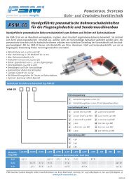
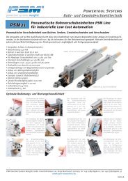
PSM21<br />
CE Declaration of Conformity<br />
PSM Line pneumatic feed unit<br />
for low-cost industrial automation<br />
<strong>Powertool</strong> <strong>Systems</strong><br />
Drilling and thread-cutting technology<br />
We, PSM <strong>Powertool</strong> <strong>Systems</strong> GmbH - Martinsried-Deutschland -, accept sole responsibility for the <strong>de</strong>claration that the product<br />
to which this <strong>de</strong>claration refers meets the regulations of Directive 98/37 EC.<br />
Tool i<strong>de</strong>ntification<br />
Type Type PSM21 drill feed and thread-cutting unit<br />
Or<strong>de</strong>r co<strong>de</strong><br />
Serial number<br />
Tool test report<br />
True running of the<br />
spindle<br />
Drill feed force,<br />
measured at 6.3 bar<br />
Idle-running speed (*)<br />
measured at 6.3 bar<br />
Noise level (**)<br />
measured at 6.3 bar<br />
[mm]<br />
[N]<br />
[min -1 ]<br />
[dB(A)]<br />
PSM 1 - - - - -<br />
Month Year Batch Batch number Customer no.<br />
0% stroke 50% stroke 100% stroke<br />
Stalling torque [Nm] when pressure is correctly set [bar]<br />
bar 0,5 1 2 3 4 5 6<br />
Nm<br />
(*) When new, the motor has a 15 to 20% lower idle-running speed. Given an appropriate running-in period, the actual speed approaches the nominal speed. (**)<br />
Measured with a standard sintered bronze sound absorber fitted. With the aid of an appropriate air extraction hose and connected filter-muffler (Art.-No. AMC520-<br />
F06B) the noise level can be greatly reduced.<br />
The following persons confirm the correctness of the above information:<br />
Martinsried, dated<br />
Robert Manglitz Piotr Gela<br />
PSM <strong>Powertool</strong> <strong>Systems</strong> Manglitz GmbH, Fraunhoferstrasse 11a, 82152 Martinsried, Germany, Tel. +49 (0)89 899621-0, Fax +49 (0)89 899621-30<br />
www.<strong>psm</strong>-<strong>muenchen</strong>.<strong>de</strong><br />
/<br />
- Page -
In<strong>de</strong>x<br />
General<br />
Design<br />
General technical information<br />
Summary of the operating functions<br />
Construction<br />
Notes on use as a screw-driver unit<br />
<strong>Powertool</strong> <strong>Systems</strong><br />
Or<strong>de</strong>ring inform. Or<strong>de</strong>r co<strong>de</strong> for PSM 1 drill feed unit 6<br />
Dimensions<br />
PSM21<br />
Tool adaptions<br />
Dimensions of the drill feed unit with 40 mm feed length<br />
Dimensions of the drill feed unit with 40 mm feed length<br />
Scale drawings of the tool adaptions<br />
Or<strong>de</strong>r co<strong>de</strong> for the tool adaptions<br />
Control Examples of a pneumatic control 9<br />
General remarks<br />
on operation<br />
Special notes<br />
on function and<br />
operation<br />
Service<br />
Spare parts and<br />
drawings<br />
Transport and handling<br />
Installation of the tool<br />
Commissioning the tool 11<br />
Maintenance and use of the tool<br />
Disposal of used appliances<br />
Packaging materials<br />
Statutory provisions<br />
Functional <strong>de</strong>scription 13<br />
Assembly instructions<br />
Compressed air connections<br />
Lubrication<br />
Stroke setting<br />
Setting the optional proximity switches<br />
Setting the speed of the working stroke<br />
Setting the speed of the rapid stroke and return stroke<br />
Start-up<br />
Repairs<br />
Maintenance<br />
Assembly drawing<br />
Explo<strong>de</strong>d assembly drawing<br />
Spare parts list 18-19<br />
PSM <strong>Powertool</strong> <strong>Systems</strong> Manglitz GmbH, Fraunhoferstrasse 11a, 82152 Martinsried, Germany, Tel. +49 (0)89 899621-0, Fax +49 (0)89 899621-30<br />
www.<strong>psm</strong>-<strong>muenchen</strong>.<strong>de</strong><br />
4<br />
5<br />
7<br />
8<br />
10<br />
12<br />
14<br />
15<br />
16<br />
17
PSM21<br />
General technical information<br />
<strong>Powertool</strong> <strong>Systems</strong><br />
Instructions for the PSM21 drill feed unit<br />
General technical information<br />
- Summary of the operating functions -<br />
The compact and light <strong>de</strong>sign makes this feed <strong>de</strong>vice an i<strong>de</strong>al component of a specialised mechanical engineering unit. The<br />
lightest version, weighing just kg is i<strong>de</strong>ally suited to use in robots. Robust drive technology and precise bronze/steel plain<br />
sleeve bearings guarantee durability and production accuracy.<br />
• Compact modular construction system<br />
• Motor output: 0.30 kW<br />
• Drilling through up to 6 mm of mild steel<br />
• Threads from M2 to M8 can be cut in mild steel<br />
• Stall torque shut-off screwdriver from 0.3 to 12.6 Nm<br />
• Standard feeds: 40 and 80 mm<br />
• Braking paths: 12.70, 25.40, 50.80 and 76.20 mm<br />
• Speeds from 600 to 29,000 rpm<br />
• Final position request with magnetic field sensors (optional)<br />
• Installation of multiple spindle cutting heads<br />
• Installation of thread-cutting heads<br />
• Low weight (i<strong>de</strong>al for robot use)<br />
• Very small dimensions<br />
• Spindle running accuracy: 0.02 mm<br />
• Drilling <strong>de</strong>pth accuracy: 0.01 mm<br />
• Air consumption: 5.4 l/sec.<br />
• Operating pressure: 6.3 bar<br />
Summary of the operating functions<br />
The stroke setting screw<br />
is fastened by means of<br />
a grub screw with a brass<br />
head. Before the overall<br />
stroke length is set, this<br />
screw must be undone with<br />
an Allen key.<br />
The braking rate is set using<br />
the internal hydraulic brake<br />
with a slotted screwdriver.<br />
The air outlet sleeve should<br />
be removed first to improve<br />
accessibility.<br />
The compressed air connections<br />
are placed centrally<br />
on the rear. A hose<br />
of 6 mm external diameter<br />
should be used for the<br />
prestroke and return stroke<br />
and a 10-mm hose for connecting<br />
the motor.<br />
PSM21 with 80 mm feed length<br />
The overall stroke length is<br />
set with the stroke setting<br />
screw. This adjusting screw<br />
has a fine pitch thread with<br />
a 1 mm pitch. The feed<br />
length can thus be adjusted<br />
very accurately.<br />
The prestroke and return<br />
stroke speed can be set<br />
using exhaust throttle. The<br />
air outlet sleeve should be<br />
removed first to improve<br />
accessibility.<br />
The motor exhaust hose is<br />
fitted as a standard with<br />
a 3/4-inch thread. Either<br />
a sound absorber can be<br />
mounted, or an exhaust<br />
hose fitted: e.g. in a filter<br />
sound absorber.<br />
PSM21 with 40 mm feed length<br />
The braking path (working<br />
stroke) is set by means of<br />
the adjusting screw. This<br />
is fitted with a Long-Lok<br />
thread-lock to prevent it<br />
being displaced during operation.<br />
Optionally, limit switches<br />
can be mounted on the<br />
sensor bar. These can be<br />
slid along the bar. There are<br />
two types of limit switch:<br />
pneumatic and electrical<br />
signal.<br />
The drill feed unit can be<br />
fastened from above or<br />
from below. A keyway is<br />
provi<strong>de</strong>d for perfectly aligned<br />
assembly. Besi<strong>de</strong>s this,<br />
the unit can also be fixed<br />
with alignment pins.<br />
PSM <strong>Powertool</strong> <strong>Systems</strong> Manglitz GmbH, Fraunhoferstrasse 11a, 82152 Martinsried, Germany, Tel. +49 (0)89 899621-0, Fax +49 (0)89 899621-30<br />
www.<strong>psm</strong>-<strong>muenchen</strong>.<strong>de</strong><br />
- Page 4 -
PSM21<br />
Construction of the PSM21<br />
<strong>Powertool</strong> <strong>Systems</strong><br />
Instructions for the PSM21 drill feed unit<br />
Construction of the PSM21<br />
- Notes on use as a screw-driver unit -<br />
The compact construction of the PSM 1 makes it possible to integrate drive, feed and braking units in a very small space.<br />
With a width of 40 mm, a height of 100 mm and a weight of approx. kg, the PSM 1 is the smallest and lightest drill feed unit<br />
available on the market. It is thus an i<strong>de</strong>al component in specialised mechanical engineering applications, and is excellently<br />
suited for use on robot arms because of its low weight.<br />
Motor exhaust<br />
Compressed air<br />
supply for return<br />
stroke<br />
Compressed air<br />
supply drive unit<br />
Attachment bar<br />
for requesting final<br />
position<br />
Notes on use as a screw-driver unit<br />
Magnets for<br />
requesting final<br />
position<br />
Feed cylin<strong>de</strong>r<br />
Compressed air supply<br />
for prestroke<br />
Hydraulic brake<br />
(working stroke)<br />
Stroke-setting spindle with integrated<br />
adjusting screw for the braking<br />
path<br />
Drive unit (motor and<br />
transmission)<br />
Mounting flange<br />
This drill feed unit can be used for drilling, cutting threads and screw fastening. In screw fastening aplications, the unit is<br />
used as a stall torque shut-off screwdriver or as a screwdriver with air switch-off. A pneumatic control for switch-off the air<br />
supply can be supplied on <strong>de</strong>mand. When using it as a stall torque shut-off screwdriver, it is important that the inlet pressure<br />
and volume flow (drive unit compressed air supply) be kept constant with a precision pressure controller. If this is the case,<br />
you will receive very accurate repeat torque accuracy, comparable with that of a mechanical cut-out coupling of an electric<br />
or pneumatic screwdriver. The <strong>de</strong>cisive advantage is that with the PSM 1, you now have a screwdriver unit with integrated<br />
feed. The use of Co<strong>de</strong> 5 with the tool hol<strong>de</strong>r option (sliding spindle with a 1/4-inch, hexagonal quick-action chuck) is recommen<strong>de</strong>d.<br />
Here, the sliding spindle is used to insert the screw bit into the chuck. This means the PSM 1 - can also be used as<br />
a screwdriver system in addition to its main purpose as a drill feed unit in an automatic screw-fastening unit. A maximum<br />
torque of approx. 13 Nm can be achieved. The precise inlet pressure acts in proportion to the stalling torque.<br />
PSM <strong>Powertool</strong> <strong>Systems</strong> Manglitz GmbH, Fraunhoferstrasse 11a, 82152 Martinsried, Germany, Tel. +49 (0)89 899621-0, Fax +49 (0)89 899621-30<br />
www.<strong>psm</strong>-<strong>muenchen</strong>.<strong>de</strong><br />
- Page 5 -
PSM21 Or<strong>de</strong>ring information<br />
<strong>Powertool</strong> <strong>Systems</strong><br />
Instructions for the PSM21 drill feed unit<br />
Or<strong>de</strong>r co<strong>de</strong> for PSM21 drill feed unit Spare parts Or<strong>de</strong>r<br />
PSM21 - - - - -<br />
Bohr- und Schneidleistung (Richtwerte)<br />
Alu Stahl<br />
1,5 1<br />
3,5 2<br />
5 3<br />
6 4<br />
7/M4 5/M3<br />
8/M6 6/M5<br />
M8 M6<br />
M10 M8<br />
Final position request<br />
0 Without request<br />
1 Pneumatic signal 5035-070-1<br />
2 Electrical signal 5035-070-2<br />
Tool hol<strong>de</strong>r<br />
1 Toothed ring drill chuck 0...6.35 mm (standard) 5035-052-1<br />
2 Collet chuck 1...10 mm (state ø) 5035-052-2<br />
3 Thread-cutting head (max. M6, 2000 min-1) 5035-052-3<br />
4 Quick-action chuck 1/4-inch, hexagonal 5035-052-4<br />
5 Sli<strong>de</strong> spindle quick-action chuck 1/4-inch, hexagonal 5035-052-5<br />
Braking paths/working stroke length max. [mm]<br />
0 Without braking unit (not for cutting threads)<br />
1 12.70 (1/2 inch) 5035-003-1/2<br />
2 25.40 (1 inch) 5035-003-1<br />
3 50.80 (2 inch) - not for 40 mm feed length 5035-003-2<br />
4 76.20 (2 inch) - not for 40 mm feed length 5035-003-3<br />
Overall stroke length max. [mm]<br />
1 40 (standard) 5035-000-40<br />
2 80 (standard) 5035-000-80<br />
3 120 (only on request) 5035-000-120<br />
4 160 (only on request) 5035-000-160<br />
5 200 (only on request) 5035-000-200<br />
Idle-running speed [min -1 ]<br />
0 29,000 (not with thread-cutting head) 5035-044-29000<br />
1 5,200 (not with thread-cutting head) 5035-044-5200<br />
2 3,800 (not with thread-cutting head) 5035-044-3800<br />
3 3,200 (not with thread-cutting head) 5035-044-3200<br />
4 2,400 5035-044-2400<br />
5 1,000 5035-044-1000<br />
6 700 5035-044-700<br />
7 600 5035-044-600<br />
PSM <strong>Powertool</strong> <strong>Systems</strong> Manglitz GmbH, Fraunhoferstrasse 11a, 82152 Martinsried, Germany, Tel. +49 (0)89 899621-0, Fax +49 (0)89 899621-30<br />
www.<strong>psm</strong>-<strong>muenchen</strong>.<strong>de</strong><br />
- Page -
PSM21 Scale drawings<br />
Dimensions of the drill feed unit with 40 mm feed length<br />
<br />
<br />
<br />
<br />
<strong>Powertool</strong> <strong>Systems</strong><br />
Instructions for the PSM21 drill feed unit<br />
<br />
<br />
<br />
<br />
<br />
<br />
<br />
<br />
<br />
<br />
<br />
<br />
<br />
<br />
<br />
<br />
<br />
<br />
<br />
<br />
<br />
<br />
<br />
Dimensions of the drill feed unit with 80 mm feed length<br />
<br />
<br />
<br />
<br />
<br />
<br />
PSM <strong>Powertool</strong> <strong>Systems</strong> Manglitz GmbH, Fraunhoferstrasse 11a, 82152 Martinsried, Germany, Tel. +49 (0)89 899621-0, Fax +49 (0)89 899621-30<br />
<br />
www.<strong>psm</strong>-<strong>muenchen</strong>.<strong>de</strong><br />
<br />
<br />
<br />
<br />
<br />
<br />
<br />
<br />
<br />
<br />
- Page 7 -
<strong>Powertool</strong> <strong>Systems</strong><br />
Instructions for the PSM21 drill feed unit<br />
PSM21 Dimensions and or<strong>de</strong>r co<strong>de</strong> for tool adaptions<br />
Scale drawings of the tool adaptions<br />
<br />
<br />
<br />
<br />
<br />
<br />
<br />
<br />
<br />
<br />
<br />
<br />
<br />
<br />
<br />
<br />
<br />
<br />
<br />
<br />
<br />
<br />
Or<strong>de</strong>r co<strong>de</strong> for the tool adaptions Spare parts Or<strong>de</strong>r<br />
PSM21 - - - - -<br />
Tool hol<strong>de</strong>r<br />
PSM <strong>Powertool</strong> <strong>Systems</strong> Manglitz GmbH, Fraunhoferstrasse 11a, 82152 Martinsried, Germany, Tel. +49 (0)89 899621-0, Fax +49 (0)89 899621-30<br />
www.<strong>psm</strong>-<strong>muenchen</strong>.<strong>de</strong><br />
<br />
<br />
1 Toothed ring drill chuck 0...6.35 mm (standard) 5035-052-1<br />
2 Collet chuck 1...10 mm (state ø) 5035-052-2<br />
3 Thread-cutting head (max. M6, 2000 min -1 ) 5035-052-3<br />
4 Quick-action chuck 1/4-inch, hexagonal 5035-052-4<br />
5 Sli<strong>de</strong> spindle with quick-action chuck 1/4-inch, hexa- 5035-052-5<br />
- Page 8 -
PSM21 Examples of a pneumatic control<br />
12<br />
2<br />
1<br />
7<br />
2<br />
9 10<br />
3<br />
2<br />
1 3<br />
12<br />
12<br />
1<br />
S 1 S 2<br />
I I<br />
2<br />
1<br />
3 4<br />
2<br />
3<br />
3<br />
1<br />
4<br />
1 5<br />
2<br />
1<br />
14<br />
6 2<br />
12<br />
12<br />
14<br />
1 2<br />
12<br />
1 3<br />
2<br />
1<br />
11<br />
1 3<br />
2<br />
1<br />
1<br />
3<br />
8<br />
13<br />
2<br />
12<br />
2<br />
<strong>Powertool</strong> <strong>Systems</strong><br />
Instructions for the PSM21 drill feed unit<br />
1<br />
5<br />
PSM21 internal, components integrated<br />
No. Designation Function<br />
1 Cylin<strong>de</strong>r, pneum. Feed<br />
2 Compressed air Transmission<br />
3 Exhaust throttle Feed rate<br />
4 Exhaust throttle Return stroke speed<br />
5 Cut-off valve Motor stop<br />
6 Impulse valve Control of the prestroke and<br />
7 OR valve Logic element<br />
8 Signal breaker Prestroke impulse<br />
9 Limit switch S1 Return stroke condition<br />
10 Manual control Reset to 0 stroke<br />
11 Manual key Start of drilling cycle<br />
12 Limit switch S2 Prestroke condition<br />
13 Manual control Main opening valve<br />
14 Maintenance unit Controllers/filters/lubricators<br />
PSM <strong>Powertool</strong> <strong>Systems</strong> Manglitz GmbH, Fraunhoferstrasse 11a, 82152 Martinsried, Germany, Tel. +49 (0)89 899621-0, Fax +49 (0)89 899621-30<br />
www.<strong>psm</strong>-<strong>muenchen</strong>.<strong>de</strong><br />
- Page 9 -
PSM21<br />
Operating instructions<br />
- General remarks on operation -<br />
<strong>Powertool</strong> <strong>Systems</strong><br />
Instructions for the PSM21 drill feed unit<br />
The operating instructions comply with the regulations contained in Directive 98/37/EEC. The appendix, in which the name<br />
and address of the manufacturer, as well as the <strong>de</strong>scription and technical tool data are listed, forms a standard part of the<br />
operating instructions. The operating instructions must be carefully kept at a place that is known to all users of the tool<br />
and which is easily accessible. Read the instructions carefully and ensure that all other operators of the tool read them<br />
before setting, conducting maintenance work, repairing or scrapping the tool. Always ensure that the operators have fully<br />
un<strong>de</strong>rstood the information contained in the operating instructions and, where appropriate, have completely un<strong>de</strong>rstood<br />
the symbols on the machine. Most acci<strong>de</strong>nts can be avoi<strong>de</strong>d when the following basic safety information from EEC Directive<br />
98/37, and the regulations on hand-held tools are followed. The regulations on the prevention of acci<strong>de</strong>nts valid in your<br />
own country must be observed and adhered to exactly. No inscriptions or stickers on the tool may be removed. This applies<br />
particularly for legally stipulated notices.<br />
Transport and handling<br />
On receipt make sure that the packaging is undamaged and that the tool does not bear any signs of transport damage. If<br />
necessary contact the PSM customer service. Please dispose of the packaging materials in a proper manner. If the tool is to<br />
be transported to another <strong>de</strong>partment at the factory or to another location, ensure that the tool and/or the accessories do<br />
not get damaged. Pack the tool appropriately.<br />
Installation of the tool<br />
The following remarks generally apply to the installation of compressed air tools. Always verify the compressed air connection<br />
pressure: Compressed air tools have their i<strong>de</strong>al range of performance at an inlet pressure of .3 Bar (90 P.S.I.) at the<br />
tool in operation.This value should not be excee<strong>de</strong>d. If the pressure at the compressed air connection is higher than the<br />
tool‘s operating pressure, insert a pressure regulator in between. During installation always provi<strong>de</strong> easily accessible supplementary<br />
fittings, to separate the tool from the energy source. Only use clean and dry compressed air (<strong>de</strong>w point between<br />
+ °C and +10°C), to protect the tool from damage, silting and rust formation. It is strongly recommen<strong>de</strong>d that an air service<br />
unit be installed between the compressed air network and the tool‘s connection coupling. Most PSM compressed air tools<br />
are <strong>de</strong>signed for operation with oil-less compressed air. The use of non-oiled compressed air reduces the service life of the<br />
rotor bla<strong>de</strong>s significantly. If you do <strong>de</strong>ci<strong>de</strong> on oiling, then filter-regulator-lubricator (FRL) power units should be used. Only<br />
employ a highly viscous, high-gra<strong>de</strong> mineral oil that is free of resin and acids. If an excessive amount of oil is used, oil will<br />
find its way into the surrounding air as an oil mist, contaminating the workplace and harming the operator. In or<strong>de</strong>r to avoid<br />
this oil mist formation, the exhaust air from the compressed air tool must be gui<strong>de</strong>d into an appropriate oil mist separator.<br />
If this is not possible, use the tool in a very well ventilated environment. Contact a doctor immediately if any oil should get<br />
into the eyes or be acci<strong>de</strong>ntally swallowed. Persons who regularly <strong>de</strong>al with lubricants must wear suitable protective clothing<br />
ma<strong>de</strong> of materials impervious to oil. Remove any clothing that has been contaminated with oil. If the technical parameters<br />
are not monitored (pressure of the compressed air supply, internal diameter of the connecting hose, etc.) damage may occur<br />
to the tool and the operator may be put at risk. Before the tool is connected, remove any dirt and con<strong>de</strong>nsation from the<br />
hose and the threa<strong>de</strong>d coupling. Make sure that any connecting pieces are fitted correctly. The use of a pivoted connection<br />
is recommen<strong>de</strong>d so that the connecting hose cannot get damaged or come off when the tool is rotated. The hose must be resistant<br />
to oil and friction, and be <strong>de</strong>signed to withstand the tool‘s operating pressure. Do not pull the tool along the ground<br />
by the hose. Always remove the hose from the tool before opening the compressed-air line. Do not use any hoses that are<br />
damaged, worn or otherwise of poor quality. Always check the hoses visually before use: Damage and injury may occur if a<br />
hose bursts. Please pay attention that compressed air hoses are correctly put away after use. They must not be stored near<br />
to sources of heat or be subjected directly to sunlight. Always ensure that the tool is separated from the compressed air<br />
supply when it is no longer in use when accessories are replaced in or<strong>de</strong>r to adjust, service or take apart the tool. Remove<br />
any compressed air tools that do not function from the workplace or make it clear that they do not work by clearly labelling<br />
PSM <strong>Powertool</strong> <strong>Systems</strong> Manglitz GmbH, Fraunhoferstrasse 11a, 82152 Martinsried, Germany, Tel. +49 (0)89 899621-0, Fax +49 (0)89 899621-30<br />
www.<strong>psm</strong>-<strong>muenchen</strong>.<strong>de</strong><br />
- Page 10 -
PSM21<br />
General remarks on operation of<br />
compressed air tools<br />
<strong>Powertool</strong> <strong>Systems</strong><br />
Instructions for the PSM21 drill feed unit<br />
them. In the case of screw-tightening systems that are equipped with several compressed air motors, provi<strong>de</strong> air columns of<br />
a<strong>de</strong>quate capacity near the motors. Avoid using quick connections with these systems because they can significantly reduce<br />
the air-flow. Depending on the type of tool used, the instructions contained in the „Special notes on function and operation<br />
of the PSM 1“ also apply in addition to the general instructions.<br />
Commissioning the tool<br />
The following generally applicable notes must be followed when using a compressed air tool. For reasons of safety, all tools<br />
and connecting pieces and accessories may only be used as properly inten<strong>de</strong>d and only with the safety <strong>de</strong>vices provi<strong>de</strong>d<br />
by the manufacturer. See also the <strong>de</strong>finition of proper use in the section on „Specific notes on ...“. Any retrofitting of the<br />
tool or its accessories must be approved by the manufacturer. Should there be any doubt about the safe use of a tool or its<br />
accessories, do not connect and start up the tool un<strong>de</strong>r any circumstances before you have discussed your doubts with the<br />
manufacturer. Compressed air tools may generate vibrations. Frequent exposure to strong vibrations over a long period of<br />
time can cause damage to health, especially to the hands and arms. The effects are still not known in <strong>de</strong>tail and <strong>de</strong>pend on<br />
numerous factors, such as the nature of the work concerned and the tool, the physical constitution of the operator, as well<br />
as the duration and nature of the exposure. In cold regions, gloves should be warm to keep the hands as warm as possible.<br />
The use of compressed air tools themselves and their working environment results in high noise levels. Ear protection must<br />
be worn when such high noise levels exist. The technical regulations and legal requirements applicable in the country where<br />
it is to be used should be observed. See the section on „Other safety information“ for further informtion on vibrations and<br />
noise levels. The user of the tool or the staff at the factory must wear protective goggles, ear muffs and plugs, safety shoes<br />
and gloves when working conditions call for it or the acci<strong>de</strong>nt prevention regulations require it. The tools are not protected<br />
against contact with electrical current. They must not be used in working spaces where there is a danger of explosion if the<br />
manufacturing procedure may set off an explosion. Make sure that accessories are mounted in a proper manner and safely,<br />
and switch the control systems to „Off“ before activating the compressed air supply. The tool‘s starting mechanism must<br />
always function correctly. The safety <strong>de</strong>vices and the tool‘s starting mechanism must not be circumvented. If the compressed<br />
air supply should fail, the starting mechanism must be stopped immediately. Moving parts must not be touched at any time<br />
if this is not expressly call for before the tool has been finally cut off from its energy source. The tool must always be kept<br />
clean and dry to ensure that it can be gripped safely. If an accessory component should break, fragments may be expelled at<br />
high speed. Unintentional movement of the tool may cause injury to the operator. When lifting the tool or putting it down,<br />
make sure that it is not inadvertently switched on. Only use the tool in safe operating positions. Particular caution is called<br />
for when working in unsuitable positions. Make sure that long hair or loose clothing does not get caught or entrained. Heavy<br />
tools must be hung on a spring balancer or similar <strong>de</strong>vice to avoid the operator being subjected to a heavy physical bur<strong>de</strong>n.<br />
The tool must always be well secured. Do not clean, oil or grease any moving parts by hand. Take particular care that the air<br />
discharge opening does not become a source of danger. This applies particularly when the air discharge openings are blocked<br />
(e.g.: because of rust, mounted cover caps, etc.). Do not put the tool to one si<strong>de</strong> as long as the accessory is in motion,<br />
and do not switch on until it has been picked up. The tool and accessory must come to a complete standstill before it can<br />
be brought to another workplace. Depending on the type of tool used, the instructions contained in the „Special notes on<br />
function and operation of the PSM 1“ also apply in addition to the general instructions.<br />
PSM <strong>Powertool</strong> <strong>Systems</strong> Manglitz GmbH, Fraunhoferstrasse 11a, 82152 Martinsried, Germany, Tel. +49 (0)89 899621-0, Fax +49 (0)89 899621-30<br />
www.<strong>psm</strong>-<strong>muenchen</strong>.<strong>de</strong><br />
- Page 11 -
PSM21<br />
Maintenance and use of the tool<br />
General remarks on operation of<br />
compressed air tools<br />
<strong>Powertool</strong> <strong>Systems</strong><br />
Instructions for the PSM21 drill feed unit<br />
Service and maintenance work on the compressed air tools must be carried out correctly by experienced and skilled employees.<br />
Cleaning and checking the tool every 1000 operating hours is recommen<strong>de</strong>d. If any vibrations, unusual noises, changes<br />
in speed or irregularities are noticed, do not continue using the tool and switch it off. It makes sense to clean the filter<br />
element in the tool‘s compressed air connection to avoid the later becoming blocked and thus preventing a reduction in the<br />
motor output. If the tool does not start after a long period at a standstill, place a few drops of oil (Art. No. 99011001) in the<br />
compressed air connections and repeat the start procedure. Always cut off the tool from the source of compressed air before<br />
any accessories are replaced, serviced or dismantled. Following every intervention for maintenance, test the tools in or<strong>de</strong>r<br />
to check their rate of advance and functionality. The spare parts list is sent separately for general information. It is only<br />
inten<strong>de</strong>d for the staff responsible. Only use original PSM spare parts. (The guarantee rights become invalid if components are<br />
used that are not original parts). Repairs that are not conducted correctly may cause acci<strong>de</strong>nts. In or<strong>de</strong>r to avoid acci<strong>de</strong>nts<br />
as a result of any unsuitable applications and to enjoy the best performances from the tool and a comprehensive customer<br />
service, repairs or maintenance work must always be conducted by the PSM Technical Customer Service, Fraunhoferstrasse<br />
11a, D-8 15 Martinsried – or by an authorised service centre in your own country. The PSM Technical Customer Service can<br />
also organise courses on the correct use and proper conduct of maintenance and repairs of PSM products on request.<br />
Disposal of used appliances<br />
This compressed air tool is ma<strong>de</strong> largely of aluminium, steel, cast iron, brass and plastic. All the components can be easily<br />
disposed of, and they are neither environmental nor health hazards. Sort the individual parts according to their materials for<br />
recycling or separate disposal. Where applicable, PSM will take back individual parts that have been dismantled and sorted<br />
according to their materials.<br />
Packaging materials<br />
PSM products are packed in maerials ma<strong>de</strong> from recovered paper and plastics, which can be recycled. The packaging material<br />
meets the regulations of European Directive 94/ /EEC.<br />
Statutory provisions<br />
1.7.1. Richtlinien Directive 98/37 EC - Safety of machinery. 1.7. . Technische Normen EN 292-1:1991 Safety of machinery. Basic concepts,<br />
general principles for <strong>de</strong>sign. Part 1: Basic terminology, methodology. EN 292-2:1991 Safety of machinery. Basic concepts, principles for<br />
<strong>de</strong>sign. Part : Technical principles and specifications. EN 792:2000 Hand-held non-electric power tools. Safety requirements. Part 1- 1 .<br />
EN 12096:1997 Mechanical vibration - Declaration and verification of vibration emission values. EN 28662-1:1992 Hand-held portable power<br />
tools - Measurement of vibrations at the handle. Part 1: General. EN ISO 8662-4:1995 Hand-held portable power tools - Measurement of<br />
vibrations at the handle. Part 4: Grin<strong>de</strong>rs. EN ISO 8662-7:1997 Hand-held portable power tools - Measurement of vibrations at the handle.<br />
Part 7:Wrenches, screwdrivers and nutrunners with impact, impulse or ratchet action. EN ISO 8662-8:1997 Hand-held portable power tools<br />
- Measurement of vibrations at the handle – Part 8: Polishers and rotary, orbital and random orbital san<strong>de</strong>rs. EN ISO 8662-13:1997 Handheld<br />
portable power tools - Measurement of vibrations at the handle. Part 13: Die grin<strong>de</strong>rs. EN ISO 3744:1995 Acoustics.Determination<br />
of sound power levels of noise sources using sound pressure. Engineering method in an essentially free field over a reflecting plane. EN<br />
ISO 15744:2002 Hand-held non-electric power tools. Noise measurement co<strong>de</strong>. Engineering method (gra<strong>de</strong> ). EN ISO 4871:1996 Acoustics<br />
- Declaration and verification of noise emission values of machinery and equipment. ISO 2787:1984 Rotary and percussive pneumatic tools.<br />
Performance tests. EN ISO 5349-1:2001 Mechanical vibration. Measurement and evaluation of human exposure to hand - transmitted vibration.<br />
Part 1: General requirements. EN ISO 5349-2:2001 Mechanical vibration. Measurement and evaluation of human exposure to hand<br />
- transmitted vibration. Part : Practical guidance for measurement at the workplace. ISO 5393:1994 Rotary tools for threa<strong>de</strong>d fasteners.<br />
Performance test method. ISO 6544:1981 Hand-held pneumatic assembly tools for installing threa<strong>de</strong>d fasteners - Reaction Torque and Torque<br />
Impulse Measurements. CR 1030-1:1995 Hand-arm vibration – Gui<strong>de</strong>lines for vibration hazards reduction – Part 1: Engineering methods<br />
by <strong>de</strong>sign of machinery. CR 1030-2:1995 Hand-arm vibration – Gui<strong>de</strong>lines for vibration hazards reduction – Part : Management measures<br />
at the workplace.<br />
PSM <strong>Powertool</strong> <strong>Systems</strong> Manglitz GmbH, Fraunhoferstrasse 11a, 82152 Martinsried, Germany, Tel. +49 (0)89 899621-0, Fax +49 (0)89 899621-30<br />
www.<strong>psm</strong>-<strong>muenchen</strong>.<strong>de</strong><br />
- Page 1 -
Functional <strong>de</strong>scription<br />
<strong>Powertool</strong> <strong>Systems</strong><br />
Instructions for the PSM21 drill feed unit<br />
PSM21 Special notes on function and operation<br />
Within the enclosure there are a double-acting compressed air cylin<strong>de</strong>r (A), a sleeve (B), in which a compressed air drive<br />
motor (44, 43) is situated, as well as the motor cut-off valve (C). There are three compressed air connections on the rear.<br />
Connection (49) acts upon the compressed air motor, connection (50) acts upon the prestroke and return stroke. At the starting<br />
and end position, the motor supply air is closed by the internal motor cut-off valve (C). As soon as the connection (50,<br />
on the right) is activated and the compressed air cylin<strong>de</strong>r traverses forward, the motor cut-off valve (C) will be opened after<br />
a stroke of mm and the motor will then start up. The sleeve now moves to the set drilling <strong>de</strong>pth. By activating the connection<br />
(50, left) the sleeve will move to its final/starting position and the motor will be switched on. The overall stroke length<br />
is set with the stroke setting screw ( ), the length of the working stroke with the internal adjusting screw (13) in ( ).<br />
<br />
<br />
<br />
<br />
<br />
<br />
<br />
<br />
<br />
<br />
<br />
<br />
<br />
<br />
<br />
<br />
<br />
<br />
<br />
<br />
<br />
<br />
<br />
<br />
<br />
<br />
<br />
<br />
<br />
<br />
<br />
<br />
<br />
<br />
<br />
<br />
<br />
<br />
<br />
<br />
<br />
<br />
<br />
PSM <strong>Powertool</strong> <strong>Systems</strong> Manglitz GmbH, Fraunhoferstrasse 11a, 82152 Martinsried, Germany, Tel. +49 (0)89 899621-0, Fax +49 (0)89 899621-30<br />
www.<strong>psm</strong>-<strong>muenchen</strong>.<strong>de</strong><br />
<br />
<br />
<br />
<br />
<br />
<br />
<br />
<br />
<br />
<br />
<br />
<br />
<br />
<br />
<br />
<br />
<br />
<br />
<br />
<br />
<br />
<br />
<br />
<br />
<br />
<br />
<br />
<br />
<br />
<br />
<br />
<br />
<br />
<br />
<br />
<br />
<br />
<br />
- Page 13 -
Assembly instructions<br />
The PSM 1 is affixed by means of screwed on plates (Fig. 14.10). You can choose between: 4x M Allen screws, from above<br />
( .5 mm hole), . 4x M screws, from below (M thread). Spacings: see Sections (I) and (J). The surface must be clean and<br />
level. The parallelism of the sleeve to the enclosure and/or screwed-on plates is achieved by means of two feather keys.<br />
Alternatively, the PSM 1 can be pinned to the surface using 4 cylindrical pins (ø 4 mm).<br />
Compressed air connections<br />
There are three compressed air connections on the rear of the PSM 1 (Fig. 14.17): 1. compressed air motor connection (middle)<br />
for hose, with an external diameter of 10 mm, . connections (right and left) for the prestroke and return stroke for the<br />
hose with an external diameter of mm. Caution! When sizing the compressed air line, please ensure that the section<br />
of the line is large enough so that there is always a pressure of 5-7 bar at the air inlet of the PSM21 when the motor is<br />
running. The air consumption is 5.4 l/sec at .3 bar.<br />
Lubrication<br />
The motor and cylin<strong>de</strong>r should be run with dry (DTP +3...+10°C), filtered (5 µm) and oiled air. You can find special and very<br />
interesting information on the subject of „Lubricating compressed air tools and transmissions“ at [www.<strong>psm</strong>-<strong>muenchen</strong>.<br />
<strong>de</strong>/<strong>psm</strong>_katalog/einzelstellenoeler_spl_ 007_10.pdf]. Caution! If you run the PSM21 free of oil, please make sure that<br />
the bla<strong>de</strong>d shutter is 6-8 times higher, for instance.<br />
Stroke setting<br />
The overall stroke consists of the fast stroke and the working stroke (Fig. 14.11). The stroke is set with two screw-components.<br />
The screw-component ( , Fig. 14.12 and Fig. 14.13) is used to set the overall stroke. Caution! First unscrew stud screw<br />
(51, Fig. 14.14). By means of the stud screw (13, Fig. 14.12 and Fig. 14.16) set the fast stroke and/or the retar<strong>de</strong>d working stroke.<br />
This adjusting screw has a Long-Lok ® thread-lock and must thus not be specially countered or secured. First tighten the<br />
stud screw again (51, Fig. 14.14). Once the stroke settings have been completed, the „optional“ proximity switches (Fig. 14.18)<br />
can be set up.<br />
Through hole 6,5 mm<br />
Pine hole Ø 4 mm<br />
Feather key<br />
Thread M6<br />
Fig. 14.10 Fig. 14.11<br />
Overall stroke Fast stroke Working<br />
<strong>Powertool</strong> <strong>Systems</strong><br />
Instructions for the PSM21 drill feed unit<br />
PSM21 Special notes on function and operation<br />
Fig. 14.12 Fig. 14.13<br />
Return<br />
Prestroke<br />
Motor connection<br />
Fig. 14.14 Fig. 14.15 Fig. 14.16 Fig. 14.17 Fig. 14.18<br />
PSM <strong>Powertool</strong> <strong>Systems</strong> Manglitz GmbH, Fraunhoferstrasse 11a, 82152 Martinsried, Germany, Tel. +49 (0)89 899621-0, Fax +49 (0)89 899621-30<br />
www.<strong>psm</strong>-<strong>muenchen</strong>.<strong>de</strong><br />
- Page 14 -
<strong>Powertool</strong> <strong>Systems</strong><br />
Instructions for the PSM21 drill feed unit<br />
PSM21 Special notes on function and operation<br />
Setting the optional proximity switches<br />
The limit switches can be supplied in two versions. Article numbers 5035-070-1 (pneumatic signal) and 5035-070-2 (electrical<br />
signal). These proximity switches are set up once the limit settings have been completed. To this end, they are pushed onto<br />
the pre-mounted bar (Fig. 15.10). Pos. front: Move the sleeve to its rear final position and push the limit switch into position<br />
until an electric or pneumatic signal is given. Rear pos.: Move the sleeve to its front final position and push the limit switch<br />
into position until an electric or pneumatic signal is given.<br />
Setting the speed of the working stroke (braking rate)<br />
The speed of the working stroke is set with the installed hydraulic brake. First, the exhaust air pipe is removed (Fig. 15.11).<br />
Then, using a screwdriver (width of bla<strong>de</strong>: ...7 mm) gradually set the feed rate by twisting it slightly to the left or the right<br />
(more slowly) on the visible brass component (Fig. 15.12) <strong>de</strong>pending on the drill speed and the material being processed.<br />
Setting the speed of the rapid stroke and return stroke<br />
The fast stroke and return stroke are set at the fitted exhaust throttle (Fig. 15.13). Caution! The speed of the fast stroke<br />
is set with the „control air return stroke“ throttle. The speed of the return stroke is set with the „control air prestroke“<br />
throttle (Fig. 15.14).<br />
Commissioning<br />
Before starting, ensure that the PSM 1 is screwed tight to the level, clean surface and that no objects can hin<strong>de</strong>r the feed<br />
movement of the sleeve. The toothed ring drill chuck or collet chucks, etc. must be tightened. In addition, a protective <strong>de</strong>vice<br />
must be installed on the machine at the factory in or<strong>de</strong>r to avoid acci<strong>de</strong>nts. Please check whether the air pressure set is<br />
sufficient. Caution! When the compressed air motor is running, there must always be an air pressure of 6.3 bar. Please<br />
also check whether the lubrication for the compressed air motor is sufficient and that the compressed air is free of water.<br />
Fig. 15.10 Fig. 15.11 Fig. 15.12 Fig. 15.13 Fig. 15.14<br />
PSM <strong>Powertool</strong> <strong>Systems</strong> Manglitz GmbH, Fraunhoferstrasse 11a, 82152 Martinsried, Germany, Tel. +49 (0)89 899621-0, Fax +49 (0)89 899621-30<br />
www.<strong>psm</strong>-<strong>muenchen</strong>.<strong>de</strong><br />
Return<br />
Prestroke<br />
Motor connection<br />
- Page 15 -
PSM21 Repair and maintenance<br />
Repairs<br />
<strong>Powertool</strong> <strong>Systems</strong><br />
Instructions for the PSM21 drill feed unit<br />
Repairs are conducted by PSM employees or other authorised specialists. We support authorised specialists by sending repair<br />
instructions or support by telephone. Caution! As a basic principle, repairs within the warranty period are performed<br />
by PSM.<br />
Maintenance<br />
Visual inspection and cleaning should be performed at regular intervals. To make this easier, the enclosure must be dismantled<br />
from the base unit. After they have been removed, all the main groups will be open and able to be checked for signs<br />
of damage. The pictures below help how the enclosure is dismantled:<br />
Fig. 16.10 Fig. 16.11 Fig. 16.12 Fig. 16.12 Fig. 16.13<br />
Fig. 16.14<br />
[Fig. 16.10] Unscrew two screws (M6) on each of the two fixing<br />
plates. Caution! The plate is pinned. Knock it off, carefully<br />
and evenly. [Fig. 16.11] Take off the sensor bar fastening (2x M6<br />
each) and [Fig. 16.12] remove the sensor bar. [Fig. 16.12] Take off<br />
the exhaust air flange (2x M5) and [Fig. 16.13]. Caution! Do not<br />
misplace the O-rings. [Fig. 16.14] With one hand, grip the unit on<br />
the sleeve, with the other hand hold the enclosure tight and then<br />
pull the unit out of the enclosure. [Fig. 16.15] View of PSM21 without<br />
enclosure.<br />
Fig. 16.15<br />
Some machine components, usually sealing elements, are subject to high levels of wear. In or<strong>de</strong>r to avoid unplanned machine<br />
downtimes, these should be replaced at previously <strong>de</strong>fined intervals, as a precaution and at the discretion of the operator.<br />
Parts subjected to wear and tear are listed below in a table.<br />
Or<strong>de</strong>r No. Description Function Clear sign of wear and <strong>de</strong>fect<br />
5035-008 Wiper Sleeve gui<strong>de</strong> protector Score marks on the sleeve, <strong>de</strong>terioration in gui<strong>de</strong> characteris-<br />
5035-046 (2x) Gui<strong>de</strong> strips Sli<strong>de</strong>way bearing for the Noise levels increase during prestroke and return stroke<br />
5035-014 Gasket on bar Piston rod gasket Sleeve does not move back at all (or only with reduced force)<br />
5035-029 Piston lining Cylin<strong>de</strong>r piston gasket Sleeve does not move backwards or forwards at all (or only with<br />
5035-027 Gui<strong>de</strong> strips Guiding the piston in the Score marks on the insi<strong>de</strong> surface of the cylin<strong>de</strong>r, damage to<br />
5035-030 Gasket on bar Valve rod gasket Reduced prestroke force (or none at all)<br />
5035-040 Flat gasket Motor air gasket Motor does not switch off at the very last final position<br />
1008914 (4x) Rotor fins Motor transmission element Motor output falls, speed reduced<br />
1009879 Ball bearing Rotor bearing Abnormal motor noises, motor shutdown<br />
1007537 Ball bearing Rotor bearing Abnormal motor noises, motor shutdow<br />
5035-060 Set of wearing parts , contains all the parts subjected to wear and tear listed above<br />
PSM <strong>Powertool</strong> <strong>Systems</strong> Manglitz GmbH, Fraunhoferstrasse 11a, 82152 Martinsried, Germany, Tel. +49 (0)89 899621-0, Fax +49 (0)89 899621-30<br />
www.<strong>psm</strong>-<strong>muenchen</strong>.<strong>de</strong><br />
- Page 1 -
PSM21 Drawings and spare parts list<br />
<br />
Assembly drawing<br />
<br />
<br />
<br />
<br />
<br />
<strong>Powertool</strong> <strong>Systems</strong><br />
Instructions for the PSM21 drill feed unit<br />
<br />
<br />
<br />
<br />
<br />
<br />
<br />
<br />
<br />
<br />
<br />
<br />
<br />
<br />
<br />
Explo<strong>de</strong>d assembly drawing<br />
<br />
<br />
<br />
<br />
<br />
<br />
<br />
<br />
<br />
<br />
<br />
<br />
<br />
<br />
<br />
<br />
<br />
<br />
<br />
<br />
<br />
<br />
<br />
<br />
<br />
<br />
<br />
<br />
<br />
<br />
<br />
<br />
<br />
PSM <strong>Powertool</strong> <strong>Systems</strong> Manglitz GmbH, Fraunhoferstrasse 11a, 82152 Martinsried, Germany, Tel. +49 (0)89 899621-0, Fax +49 (0)89 899621-30<br />
www.<strong>psm</strong>-<strong>muenchen</strong>.<strong>de</strong><br />
<br />
<br />
<br />
<br />
<br />
<br />
<br />
<br />
<br />
<br />
<br />
<br />
<br />
<br />
<br />
<br />
<br />
<br />
<br />
<br />
<br />
<br />
<br />
<br />
<br />
<br />
<br />
<br />
<br />
<br />
<br />
<br />
<br />
<br />
<br />
<br />
<br />
<br />
<br />
<br />
<br />
<br />
<br />
<br />
<br />
<br />
<br />
<br />
<br />
<br />
<br />
<br />
<br />
<br />
<br />
<br />
<br />
<br />
<br />
<br />
<br />
<br />
<br />
<br />
<br />
<br />
<br />
<br />
<br />
<br />
<br />
<br />
<br />
<br />
<br />
<br />
<br />
<br />
<br />
<br />
<br />
<br />
<br />
<br />
<br />
<br />
<br />
<br />
<br />
<br />
<br />
<br />
<br />
<br />
<br />
<br />
<br />
<br />
<br />
<br />
<br />
<br />
<br />
<br />
<br />
- Page 17 -
PSM21 Drawings and spare parts list<br />
<strong>Powertool</strong> <strong>Systems</strong><br />
Instructions for the PSM21 drill feed unit<br />
Item No. of Unit Designation Drawing No. Remark<br />
1 1,00 Unit ENCLOSURE 5035-001-40 40 MM STROKE<br />
1 1,00 Unit ENCLOSURE 5035-001-80 80 MM STROKE<br />
1,00 Unit END PLATE 5035-00<br />
3 1,00 Unit HYDRAULIC BRAKE 5035-003-1/ 1 .70 MM BRAKING PATH<br />
3 1,00 Unit HYDRAULIC BRAKE 5035-003-1 5.40 MM BRAKING PATH<br />
3 1,00 Unit HYDRAULIC BRAKE 5035-003- 50.80 MM BRAKING PATH<br />
3 1,00 Unit HYDRAULIC BRAKE 5035-003-3 7 . 0 MM BRAKING PATH<br />
4 1,00 Unit CARRIER PLATE 5035-004<br />
5 ,00 Unit DISK MAGNET 5035-005<br />
1,00 Unit STROKE SETTING SCREW 5035-00 -40 40 MM STROKE<br />
1,00 Unit STROKE SETTING SCREW 5035-00 -80 80 MM STROKE<br />
7 1,00 Unit FRONT PLATE 5035-007<br />
8 1,00 Unit WIPER SLEEVE 5035-008<br />
9 1,00 Unit GUIDE BUSH 5035-009<br />
10 1,00 Unit MOTOR ENCLOSURE 5035-010<br />
11 1,00 Unit SLEEVE 5035-011-40 40 MM STROKE<br />
11 1,00 Unit SLEEVE 5035-011-80 80 MM STROKE<br />
1 1,00 Unit HOLDER FOR MOTOR 5035-01 -40 40 MM STROKE<br />
1 1,00 Unit HOLDER FOR MOTOR 5035-01 -80 80 MM STROKE<br />
13 1,00 Unit BRAKE ADJUSTING SCREW 5035-013 M1 X5 -M/LONG LOK (STEEL BRONZE-FINISH]<br />
14 1,00 Unit GASKET ON BAR 5035-014 0X 9X ,8 (NBR)<br />
15 1,00 Unit PISTON ROD GUIDE 5035-015<br />
1 1,00 Unit O-RING 5035-01 33X1 (NBR)<br />
17 1,00 Unit O-RING 5035-017 9X1,5 (NBR)<br />
18 1,00 Unit VALVE ROD 5035-018-40 40 MM STROKE<br />
18 1,00 Unit VALVE ROD 5035-018-80 80 MM STROKE<br />
19 1,00 Unit PISTON ROD 5035-019-40 40 MM STROKE<br />
19 1,00 Unit PISTON ROD 5035-019-80 80 MM STROKE<br />
0 1,00 Unit PISTON 5035-0 0<br />
1 1,00 Unit AIR SUPPLY 5035-0 1<br />
1,00 Unit CYLINDER TUBE 5035-0 -40 40 MM STROKE<br />
1,00 Unit CYLINDER TUBE 5035-0 -80 80 MM STROKE<br />
3 1,00 Unit AIR OUTLET SLEEVE 5035-0 3-1-<br />
3 1,00 Unit AIR OUTLET SLEEVE 5035-0 3-1-3<br />
4 ,00 Unit SENSOR PLATE 5035-0 4<br />
5 1,00 Unit SENSOR BAR 5035-0 5-40 40 MM STROKE<br />
5 1,00 Unit SENSOR BAR 5035-0 5-80 80 MM STROKE<br />
1,00 Unit ADAPTER - „KOSTA“ / DRIVE 5035-0<br />
PSM <strong>Powertool</strong> <strong>Systems</strong> Manglitz GmbH, Fraunhoferstrasse 11a, 82152 Martinsried, Germany, Tel. +49 (0)89 899621-0, Fax +49 (0)89 899621-30<br />
www.<strong>psm</strong>-<strong>muenchen</strong>.<strong>de</strong><br />
- Page 18 -
PSM21 Drawings and spare parts list<br />
Item No. of Unit Designation Drawing No. Remark<br />
7 1,00 Unit PISTON GUIDE BELT 5035-0 7 X1.5X105 (PTFE)<br />
8 ,00 Unit O-RING 5035-0 8 4X1.5 (NBR)<br />
9 1,00 Unit PISTON LINING 5035-0 9 3X3 X .9 (NBR)<br />
30 1,00 Unit GASKET ON BAR 5035-030 1 x19x .3 (NBR)<br />
31 8,00 Unit ALLEN SCREW 5035-031 DIN91 /M5 X 1 STEEL, GALV. (8.8)<br />
3 1,00 Unit SOUND ABSORBER 5035-03 SINTERED BRONZE [3/4 INCH]<br />
33 7,00 Unit ALLEN SCREW 5035-033 DIN91 /M4X 0 STEEL GALV. (8.8)<br />
34 ,00 Unit ALLEN SCREW 5035-034 DIN91 /M5X 0-STEEL GALV. (8.8)<br />
35 ,00 Unit FASTENING PLATE 5035-035<br />
3 1,00 Unit FLANGE - CNTRL / EXHAUST 5035-03<br />
37 4,00 Unit THREADED ROD 5035-037-40 40 MM STROKE<br />
37 4,00 Unit THREADED ROD 5035-037-80 80 MM STROKE<br />
38 1,00 Unit VALVE PISTON 5035-038<br />
39 1,00 Unit SUPPORTING WASHER 5035-039<br />
40 1,00 Unit FLAT GASKET 5035-040<br />
41 1,00 Unit PRESSURE DISC 5035-041<br />
<strong>Powertool</strong> <strong>Systems</strong><br />
Instructions for the PSM21 drill feed unit<br />
4 1,00 Unit ALLEN SCREW 5035-04 DIN91 /M .5X -V A<br />
43 1,00 Unit COMPRESSED AIR MOTOR 5035-043-XXX SEE SEPARATE SPARES LIST<br />
44 1,00 Unit COMP. AIR MOTOR / TRANSM. 5035-044- 9000 0.30 KW/ 9000 RPM<br />
44 1,00 Unit COMP. AIR MOTOR / TRANSM. 5035-044-5 00 0.30 KW/5 00 RPM<br />
44 1,00 Unit COMP. AIR MOTOR / TRANSM. 5035-044-3800 0.30 KW/3800 RPM<br />
44 1,00 Unit COMP. AIR MOTOR / TRANSM. 5035-044-3 00 0.30 KW/3 00 RPM<br />
44 1,00 Unit COMP. AIR MOTOR / TRANSM. 5035-044- 400 0.30 KW/ 400 RPM<br />
44 1,00 Unit COMP. AIR MOTOR / TRANSM. 5035-044-1000 0.30 KW/1000 RPM<br />
44 1,00 Unit COMP. AIR MOTOR / TRANSM. 5035-044-700 0.30 KW/700 RPM<br />
44 1,00 Unit COMP. AIR MOTOR / TRANSM. 5035-044- 00 0.30 KW/ 00 RPM<br />
45 1,00 Unit HOSE 5035-045-40 40 MM STROKE 4X .5X50-BLUE (PU)<br />
45 1,00 Unit HOSE 5035-045-80 80 MM STROKE 4X .5X85-BLUE (PU)<br />
4 ,00 Unit PISTON RING 5035-04 X1,5X3 (PTFE)<br />
47 1,00 Unit ANGULAR MALE SCREW JOINT 5035-047 M5-F/HOSE 4X ,5<br />
48 1,00 Unit STRAIGHT MALE SCREW JOINT 5035-048 M5-F/HOSE 4X ,5<br />
49 1,00 Unit STRAIGHT CONNECTION 5035-049 1/4INCH-F/HOSE 10MM<br />
50 ,00 Unit THROTTLE CHECK VALVE 5035-050 M5-F/HOSE MM<br />
51 1,00 Unit PRESSURE SCREW 5035-051 M5X8-M/BRASS HEAD<br />
5 1,00 Unit TOOTHED RING DRILL CHUCK 5035-05 3/8- 4/0- ,35 MM<br />
53 ,00 Unit STUD SCREW / PIVOT 5035-053 DIN915-M3X4 (A1A)<br />
54 4,00 Unit HEXAGONAL NUT 5035-054 DIN934-M4-STEEL GALV.<br />
55 4,00 Unit CYLINDRICAL PIN 5035-055 DIN7-3X14-M (A1A)<br />
PSM <strong>Powertool</strong> <strong>Systems</strong> Manglitz GmbH, Fraunhoferstrasse 11a, 82152 Martinsried, Germany, Tel. +49 (0)89 899621-0, Fax +49 (0)89 899621-30<br />
www.<strong>psm</strong>-<strong>muenchen</strong>.<strong>de</strong><br />
- Page 19 -
Call us up !<br />
Our hotline +49 (0)89 899621-15<br />
Copyright by PSM /// All rights reserved<br />
Illustrations are for information only and non-binding. We reserve the right to make technical changes.<br />
[Vers. 03/2008] Printed in Germany by KK-Druck, D- 82152 Martinsried<br />
PSM <strong>Powertool</strong> <strong>Systems</strong> Manglitz GmbH Fon +49 (0)89 899 1-0 RG: Munich local court Bank <strong>de</strong>tails Münchner Bank eG<br />
Fraunhofer Strasse 11a Fax +49 (0)89 899 1-30 HRB 10 533 Kto 93483 BLZ 701 900 00<br />
D- 8 15 Martinsried bei München www.<strong>psm</strong>-<strong>muenchen</strong>.<strong>de</strong> Ust.-Id-Nr. DE 15 183 511 BIC GENODEF1M01<br />
GF: Dipl.-Ing. Robert Manglitz info@<strong>psm</strong>-<strong>muenchen</strong>.<strong>de</strong> St.Nr. 143/173/307 4 IBAN DE9 701900000000093483