Powertool Systems - psm-muenchen.de
Powertool Systems - psm-muenchen.de
Powertool Systems - psm-muenchen.de
You also want an ePaper? Increase the reach of your titles
YUMPU automatically turns print PDFs into web optimized ePapers that Google loves.
Assembly instructions<br />
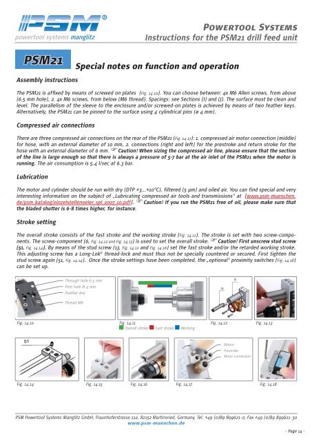
The PSM 1 is affixed by means of screwed on plates (Fig. 14.10). You can choose between: 4x M Allen screws, from above<br />
( .5 mm hole), . 4x M screws, from below (M thread). Spacings: see Sections (I) and (J). The surface must be clean and<br />
level. The parallelism of the sleeve to the enclosure and/or screwed-on plates is achieved by means of two feather keys.<br />
Alternatively, the PSM 1 can be pinned to the surface using 4 cylindrical pins (ø 4 mm).<br />
Compressed air connections<br />
There are three compressed air connections on the rear of the PSM 1 (Fig. 14.17): 1. compressed air motor connection (middle)<br />
for hose, with an external diameter of 10 mm, . connections (right and left) for the prestroke and return stroke for the<br />
hose with an external diameter of mm. Caution! When sizing the compressed air line, please ensure that the section<br />
of the line is large enough so that there is always a pressure of 5-7 bar at the air inlet of the PSM21 when the motor is<br />
running. The air consumption is 5.4 l/sec at .3 bar.<br />
Lubrication<br />
The motor and cylin<strong>de</strong>r should be run with dry (DTP +3...+10°C), filtered (5 µm) and oiled air. You can find special and very<br />
interesting information on the subject of „Lubricating compressed air tools and transmissions“ at [www.<strong>psm</strong>-<strong>muenchen</strong>.<br />
<strong>de</strong>/<strong>psm</strong>_katalog/einzelstellenoeler_spl_ 007_10.pdf]. Caution! If you run the PSM21 free of oil, please make sure that<br />
the bla<strong>de</strong>d shutter is 6-8 times higher, for instance.<br />
Stroke setting<br />
The overall stroke consists of the fast stroke and the working stroke (Fig. 14.11). The stroke is set with two screw-components.<br />
The screw-component ( , Fig. 14.12 and Fig. 14.13) is used to set the overall stroke. Caution! First unscrew stud screw<br />
(51, Fig. 14.14). By means of the stud screw (13, Fig. 14.12 and Fig. 14.16) set the fast stroke and/or the retar<strong>de</strong>d working stroke.<br />
This adjusting screw has a Long-Lok ® thread-lock and must thus not be specially countered or secured. First tighten the<br />
stud screw again (51, Fig. 14.14). Once the stroke settings have been completed, the „optional“ proximity switches (Fig. 14.18)<br />
can be set up.<br />
Through hole 6,5 mm<br />
Pine hole Ø 4 mm<br />
Feather key<br />
Thread M6<br />
Fig. 14.10 Fig. 14.11<br />
Overall stroke Fast stroke Working<br />
<strong>Powertool</strong> <strong>Systems</strong><br />
Instructions for the PSM21 drill feed unit<br />
PSM21 Special notes on function and operation<br />
Fig. 14.12 Fig. 14.13<br />
Return<br />
Prestroke<br />
Motor connection<br />
Fig. 14.14 Fig. 14.15 Fig. 14.16 Fig. 14.17 Fig. 14.18<br />
PSM <strong>Powertool</strong> <strong>Systems</strong> Manglitz GmbH, Fraunhoferstrasse 11a, 82152 Martinsried, Germany, Tel. +49 (0)89 899621-0, Fax +49 (0)89 899621-30<br />
www.<strong>psm</strong>-<strong>muenchen</strong>.<strong>de</strong><br />
- Page 14 -


