RoHS Directive Technical Guide
RoHS Directive Technical Guide
RoHS Directive Technical Guide

Create successful ePaper yourself
Turn your PDF publications into a flip-book with our unique Google optimized e-Paper software.
Farnell <strong>Guide</strong> to <strong>RoHS</strong> Compliance<br />
A Premier Farnell Company<br />
<strong>RoHS</strong> <strong>Directive</strong> <strong>Technical</strong> <strong>Guide</strong><br />
Web: www.global-legislation.com<br />
Web: www.element-14.com<br />
Q&A: glegislation@premierfarnell.com<br />
For the fastest breaking news<br />
http://twitter.com/legislationeye<br />
Version 2 June 2010<br />
Design with the best
Introduction to the requirements of the <strong>RoHS</strong> <strong>Directive</strong> 2002/95/EC <strong>RoHS</strong><br />
The Restriction of the use of certain<br />
Hazardous Substances (<strong>RoHS</strong>) <strong>Directive</strong><br />
came into force on 1st July 2006. From<br />
this date, producers of certain categories<br />
of electrical and electronic equipment will<br />
not be able to place on the market products<br />
that contain six “banned” substances<br />
unless specific exemptions apply.<br />
z<br />
z<br />
z<br />
z<br />
z<br />
z<br />
Lead - (Pb)<br />
Mercury - (Hg)<br />
Hexavalent chromium - (Cr(VI))<br />
Cadmium - (Cd)<br />
Polybrominated biphenyl flame retardants - (PBB)<br />
Polybrominated diphenyl ether flame retardants - (PBDE)<br />
The <strong>Directive</strong> applies to electrical and electronic equipment<br />
that is dependent on electric or electromagnetic fields in<br />
order to work properly. Also, equipment for the generation,<br />
transfer and measurement of such currents and fields falling<br />
within 8 product categories (below) and designed for use<br />
with a voltage rating not exceeding 1,000 volts for alternating<br />
current and 1,500 volts for direct current<br />
The scope is eight of the ten categories of the Waste Electrical<br />
and Electronic Equipment (WEEE) <strong>Directive</strong>. These are:<br />
1. Large household appliances<br />
2. Small household appliances<br />
3. IT and telecommunications equipment<br />
4. Consumer equipment<br />
5. Lighting equipment (including light bulbs, and luminaires in<br />
households)<br />
6. Electrical and electronic tools (except large scale stationary<br />
industrial tools)<br />
7. Toys, leisure and sports equipment<br />
10. Automatic dispensers<br />
Categories 8 (medical devices) and 9 (monitoring and control instruments)<br />
are expected to fall within scope by 2014<br />
1<br />
What is a compliant product?<br />
The <strong>RoHS</strong> <strong>Directive</strong> applies to equipment that is within<br />
the scope of the <strong>Directive</strong>. None of the “homogeneous<br />
materials” within compliant products must contain the six<br />
restricted substances at concentrations above the “maximum<br />
concentration values”.<br />
Who is responsible?<br />
Producers of equipment are held responsible for ensuring<br />
that their products do not contain the six restricted<br />
substances. The <strong>Directive</strong> does not cover components or subassemblies<br />
and so the equipment producers will have to take<br />
their own steps to ensure that all parts and materials used in<br />
their products do not contain restricted substances.<br />
“Producer” means any person who, irrespective of the<br />
selling technique used:<br />
(i) manufactures and sells electrical and electronic<br />
equipment under his own brand;<br />
(ii) resells under his own brand equipment produced by other<br />
suppliers; or<br />
(iii) imports or exports electrical and electronic equipment on<br />
a professional basis into a member state.<br />
It is clear from this that there will be circumstances in which<br />
it is not the actual manufacturer of a product who will assume<br />
the “producer” responsibilities.<br />
What are the maximum concentration<br />
values (MCV)?<br />
These are 0.1 percent by weight of lead, mercury,<br />
hexavalent chromium, PBB and PBDE and 0.01 percent by<br />
weight cadmium in homogeneous materials.<br />
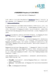
What is a homogeneous material?<br />
A homogeneous material cannot be mechanically broken<br />
down (by cutting, grinding, crushing etc) into different<br />
materials - examples would be plastic, ceramic, glass,<br />
metal etc. A semiconductor package, for example, will<br />
contain several, see below<br />
Homogeneous material – semiconductor package example<br />
© 2010 Premier Farnell plc Permission is granted for reproduction in whole<br />
or in part provided Premier Farnell plc is credited.
What Product Categories need to comply<br />
The list of products below each category heading is<br />
illustrative and not exhaustive.<br />
1. Large household appliances<br />
(Such as large cooling appliances; refrigerators; freezers;<br />
other large appliances used for refrigeration, conservation<br />
and storage of food; washing machines; clothes dryers;<br />
dish washing machines; cooking; electric stoves; electric<br />
hot plates; microwaves; other large appliances used for<br />
cooking and other processing of food; electric heating<br />
appliances; electric radiators; other large appliances for<br />
heating rooms, beds, seating furniture; electric fans; air<br />
conditioner appliances; other fanning, exhaust ventilation and<br />
conditioning equipment)<br />
2. Small household appliances<br />
(Such as vacuum cleaners; carpet sweepers; other appliances<br />
for cleaning; appliances used for sewing, knitting, weaving and<br />
other processing for textiles; irons and other appliances for<br />
ironing, mangling and other care of clothing; toasters; fryers;<br />
grinders, coffee machines and equipment for opening or<br />
sealing of containers or packages; electric knives; appliances<br />
for hair-cutting, hair drying, tooth brushing, shaving, massage<br />
and other body care appliances; clocks, watches and equipment<br />
for the purpose of measuring, indicating or registering time;<br />
scales)<br />
3. IT and telecommunications equipment<br />
(Such as centralised data processing; mainframes;<br />
minicomputers; printer units; personal computing; personal<br />
computers, including the CPU, mouse and keyboard; laptop<br />
computers, including the CPU, mouse and keyboard; notebook<br />
computers; notepad computers; printers; copying equipment;<br />
electrical and electronic typewriters; pocket and desk<br />
calculators; other products and equipment for the collection,<br />
storage, processing, presentation or communication of<br />
information by electronic means; user terminals and systems;<br />
facsimile; telex; telephones; pay telephones; cordless<br />
telephones; cellular telephones; answering systems; other<br />
products or equipment of transmitting sound, images or other<br />
information by telecommunications)<br />
© 2010 Premier Farnell plc Permission is granted for reproduction in whole<br />
or in part provided Premier Farnell plc is credited.<br />
2<br />
4. Consumer equipment<br />
(Such as radio sets; television sets; video cameras; video<br />
recorders; hi-fi recorders; audio amplifiers; musical<br />
instruments; other products or equipment for the purpose of<br />
recording or reproducing sound or images, including signals<br />
or other technologies for the distribution of sound and image<br />
than by telecommunications)<br />
5. Lighting equipment, (including electric<br />
light bulbs and household luminaires)<br />
(Such as luminaires for fluorescent lamps; straight fluorescent<br />
lamps; compact fluorescent lamps; high intensity discharge<br />
lamps, including pressure sodium lamps and metal halide<br />
lamps; low pressure sodium lamps; other lighting equipment<br />
for the purpose of spreading or controlling light)<br />
6. Electrical and electronic tools (with<br />
the exception of large-scale stationary<br />
industrial tools)<br />
(Such as drills; saws; sewing machines; equipment for turning,<br />
milling, sanding, grinding, sawing; cutting; shearing; drilling;<br />
making holes; punching; folding; bending or similar processing<br />
of wood, metal and other materials; tools for riveting, nailing<br />
or screwing or removing rivets, nails, screws or similar uses;<br />
tools for welding, soldering or similar use; equipment for<br />
spraying, spreading, dispersing or other treatment of liquid<br />
or gaseous substances by other means; tools for mowing or<br />
other gardening activities)<br />
7. Toys, leisure and sports equipment<br />
(Such as electric trains or car racing sets; hand-held video<br />
game consoles; video games; computers for biking, diving,<br />
running, rowing, etc.; sports equipment with electric or<br />
electronic components; coin slot machines)<br />
8. Automatic dispensers<br />
(Such as automatic dispensers for hot drinks; automatic<br />
dispensers for hot or cold bottles or cans; automatic<br />
dispensers for solid products; automatic dispensers for<br />
money; all appliances which deliver automatically all kind of<br />
products)
Exemptions to the <strong>RoHS</strong> <strong>Directive</strong><br />
No. Description<br />
1. Mercury in compact fluorescent lamps not exceeding 5 mg per lamp.<br />
2. Mercury in straight fluorescent lamps for general purposes not exceeding:<br />
— halophosphate 10 mg<br />
— triphosphate with normal lifetime 5 mg<br />
— triphosphate with long lifetime 8 mg.<br />
3. Mercury in straight fluorescent lamps for special purposes.<br />
4. Mercury in other lamps not specifically mentioned in this Annex.<br />
5. Lead in glass of cathode ray tubes, electronic components and fluorescent tubes.<br />
6. Lead as an alloying element in steel containing up to 0,35 % lead by weight, aluminium containing up to 0,4 % lead by weight and as a copper alloy containing up to 4 % lead by<br />
weight.<br />
7. — lead in high melting temperature type solders (i.e. lead based alloys containing 85 % by weight or more lead)<br />
— lead in solders for servers, storage and storage array systems, network infrastructure equipment for switching, signalling, transmission as well as network management for<br />
telecommunications<br />
— lead in electronic ceramic parts (e.g. piezoelectronic devices).<br />
8. Cadmium and its compounds in electrical contacts and cadmium plating except for applications banned under <strong>Directive</strong> 91/338/EEC (1) amending <strong>Directive</strong> 76/769/EEC (2) relating to<br />
restrictions on the marketing and use of certain dangerous substances and preparations.<br />
9. Hexavalent chromium as an anti-corrosion of the carbon steel cooling system in absorption refrigerators.<br />
9a DecaBDE in polymeric applications DELETED 1 JULY 2008<br />
9b Lead in lead-bronze bearing shells and bushes<br />
11. Lead used in compliant pin connector systems.<br />
12. Lead as a coating material for the thermal conduction module c-ring.<br />
13. Lead and cadmium in optical and filter glass.<br />
14. Lead in solders consisting of more than two elements for the connection between the pins and the package of microprocessors with a lead content of more than 80% and less than<br />
85% by weight.<br />
15. Lead in solders to complete a viable electrical connection between semiconductor die and carrier within integrated circuit Flip Chip packages.<br />
16. Lead in linear incandescent lamps with silicate coated tubes.<br />
17. Lead halide as radiant agent in High Intensity Discharge (HID) lamps used for professional reprography applications.<br />
18. Lead as activator in the fluorescent powder (1% lead by weight or less) of discharge lamps when used as sun tanning lamps containing phosphors such as BSP (BaSi2O5:Pb) as well as<br />
when used as speciality lamps for diazo-printing reprography, lithography, insect traps, photochemical and curing processes containing phosphors such as SMS ((Sr,Ba)2MgSi2O7:Pb).<br />
19. Lead with PbBiSn-Hg and PbInSn-Hg in specific compositions as main amalgam and with PbSn-Hg as auxiliary amalgam in very compact Energy Saving Lams (ESL).<br />
20. Lead oxide in glass used for bonding front and rear substrates of flat fluorescent lamps used for Liquid Crystal Displays (LCD).<br />
21. Lead and cadmium in printing inks for the application of enamels on borosilicate glass.<br />
22. Lead as impurity in RIG (rare earth iron garnet) Faraday rotators used for fibre optic communications systems until 31 December 2009.<br />
23. Lead in finishes of fine pitch components other than connectors with a pitch of 0.65 mm or less with NiFe lead frames and lead in finishes of fine pitch components other than<br />
connectors with a pitch of 0.65 mm or less with copper lead-frames.<br />
24. Lead in solders for the soldering to machined through hole discoidal and planar array ceramic multilayer capacitors.<br />
25. Lead oxide in plasma display panels (PDP) and surface conduction electron emitter displays (SED) used in structural elements; notably in the front and rear glass dielectric layer, the bus<br />
electrode, the black stripe, the address electrode, the barrier ribs, the seal frit and frit ring as well as in print pastes.<br />
26. Lead oxide in the glass envelope of Black Light Blue (BLB) lamps.<br />
27. Lead alloys as solder for transducers used in high-powered (designated to operate for several hours at acoustic power levels of 125 dB SPL and above) loudspeakers.<br />
28. Hexavalent chromium in corrosive preventive coatings of unpainted metal sheetings and fasteners used for corrosion protection and Electromagnetic Interference Shielding in equipment<br />
falling under category three of <strong>Directive</strong> 2002/96/EC (IT and telecommunications equipment). Exemption granted until 1 July 2007. EXPIRED<br />
29. Lead bound in crystal glass as defined in Annex 1 (Categories 1, 2, 3 and 4) of Council <strong>Directive</strong> 69/493/EEC<br />
30 Cadmium alloys as electrical/mechanical solder joints to electrical conductors located directly on the voice coil in transducers used in high-powered loudspeakers with sound pressure<br />
levels of 100 dB (A) and more.<br />
31 Lead in soldering materials in mercury free flat fluorescent lamps (which e.g. are used for liquid crystal displays, design or industrial lighting).<br />
32 Lead oxide in seal frit used for making window assemblies for Argon and Krypton laser tubes.<br />
33 Lead in solders for the soldering of thin copper wires of 100 μm diameter and less in power transformers<br />
34 Lead in cermet-based trimmer potentiometer elements<br />
35 Cadmium in photoresistors for optocouplers applied in professional audio equipment until 31 December 2009<br />
36 Mercury used as a cathode sputtering inhibitor in DC plasma displays with a content up to 30 mg per display until 1 July 2010<br />
37 Lead in the plating layer of high voltage diodes on the basis of a zinc borate glass body<br />
38 Cadmium and cadmium oxide in thick film pastes used on aluminium bonded beryllium oxide<br />
© 2010 Premier Farnell plc Permission is granted for reproduction in whole<br />
or in part provided Premier Farnell plc is credited.<br />
3
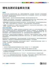
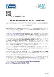
Restricted substances -where they might be found<br />
Substances Application<br />
Lead Solders<br />
Termination coatings on components<br />
Paints as pigments and as driers<br />
PVC as a stabiliser<br />
Batteries (not covered by <strong>RoHS</strong> <strong>Directive</strong>)<br />
Cadmium Electroplated coatings<br />
Special solders (e.g. in some types of fuse)<br />
Electric contacts, relays, switches<br />
PVC stabiliser<br />
Plastics, glass and ceramic pigments<br />
In some glass and ceramic materials<br />
Mercury Lamps<br />
Sensors<br />
Relays<br />
Hexavalent chromium Passivation coatings on metals<br />
In corrosion resistant paints<br />
PBB and PBDE Flame retardants in plastics<br />
Potentiometer,<br />
may contain<br />
cadmium<br />
internally<br />
Lamp, glass<br />
and solder may<br />
contain lead<br />
Plastic<br />
connector<br />
and cable<br />
insulation may<br />
contain lead or<br />
cadmium<br />
MLCC, lead<br />
in ceramic is<br />
exempt but lead<br />
in termination is<br />
banned<br />
© 2010 Premier Farnell plc Permission is granted for reproduction in whole<br />
or in part provided Premier Farnell plc is credited.<br />
4<br />
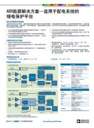
Lead in solder<br />
or termination<br />
coating<br />
Plastic<br />
housings,<br />
PBB, PBDE,<br />
cadmium<br />
and lead<br />
Electrolytic<br />
capacitor; lead<br />
in termination<br />
coatings and in<br />
plastic cover if<br />
PVC<br />
Cadmium or<br />
lead in plastic<br />
and lead in<br />
electroplated<br />
coatings
<strong>RoHS</strong> – Impact on the Electronics Design Engineer<br />
The EU <strong>RoHS</strong> <strong>Directive</strong> restricts the use of<br />
six hazardous substances in eight product<br />
categories of electrical equipment.<br />
Typical examples of products currently in<br />
scope:<br />
External hard drives, memory cards, bluetooth adapters,<br />
digital cameras, keyboards, IT cables, mouse, printers,<br />
Ethernet switches, routers, PCI cards, calculators, clocks,<br />
laser pointer, telephones, headphones, 2-way radios, modem<br />
adaptors, electric grinders, electric drills, soldering irons,<br />
vacuum cleaners, battery chargers (may be regarded as<br />
tools), torch, etc.<br />
Medical equipment and monitoring and control instruments<br />
are currently excluded from <strong>RoHS</strong> but this is likely to<br />
change following a review of scope driven by the European<br />
Commission.<br />
A hypothetical example of an electrical product is used here<br />
as a case study to illustrate what manufacturers need to do to<br />
comply with <strong>RoHS</strong>.<br />
Actions required:<br />
z First set up a team to implement the changes required.<br />
This should include production, quality, R&D and<br />
purchasing. One of the roles of this team should be to<br />
monitor <strong>RoHS</strong> legislation world-wide. This is constantly<br />
developing and changes could affect new product design.<br />
z Contact suppliers to determine if <strong>RoHS</strong> compliant<br />
components are available – if any have been withdrawn<br />
then a re-design of the product may well be required.<br />
• New circuit layouts are relatively straightforward but<br />
rewriting software for newer types of microprocessor,<br />
for example, can be very time consuming.<br />
z Contact PCB sub-contractors if these are not made<br />
in-house to determine if lead-free soldering is available – if<br />
not an alternative sub-contractor will be required<br />
z<br />
If soldering is carried out in-house, this will need to be<br />
changed to lead-free.<br />
• Lead-free soldering is very different to tin/lead. The<br />
higher temperatures required can damage some types<br />
of components and laminates so alternatives may<br />
need to be used. A sufficiently high temperature is<br />
needed to form good solder joints but this should not<br />
be any higher than necessary to avoid heat damage to<br />
components or the laminate.<br />
To achieve this compromise, new soldering equipment<br />
may be required.<br />
© 2010 Premier Farnell plc Permission is granted for reproduction in whole<br />
or in part provided Premier Farnell plc is credited.<br />
5<br />
• Lead-free prototype products will need to be made in<br />
sufficient numbers to validate the production process<br />
and to provide samples for quality and reliability testing.<br />
Both of these can be compromised when changing to<br />
lead-free soldering if this is not carried out correctly.<br />
z If any aluminium or galvanised steel parts are treated with<br />
passivation chemicals, these are likely to be hexavalent<br />
chromium based and an alternative will be required.<br />
Suppliers of sub-assemblies will also need to be informed<br />
of this requirement.<br />
• Find a suitable sub-contractor who is able to coat parts<br />
with one of the relatively new passivation materials.<br />
The substitutes that are available are suitable for most<br />
applications but are not as easy to apply as hexavalent<br />
chromium, therefore prototype testing is advisable.<br />
z Set up a <strong>RoHS</strong> compliance procedure. This will be required<br />
to assess and audit suppliers, check incoming parts and<br />
test any high risk materials such as bright yellow plastic<br />
(cadmium or hexavalent chromium) and PVC cable<br />
insulation (lead). This procedure will need to be followed<br />
and documented to ensure that non-compliant parts are<br />
not used and to provide evidence of due diligence if the<br />
<strong>RoHS</strong> enforcement body requests this information.<br />
z<br />
Staff training will be required; for optical inspection,<br />
rework, assessing whether parts are <strong>RoHS</strong> compliant, etc.<br />
Changing products to comply with <strong>RoHS</strong> is not<br />
straightforward. Manufacturers who have already changed<br />
found that the process took up to four years and costs can<br />
be considerable. Having eliminated the six <strong>RoHS</strong> substances,<br />
this is not the end. The EC is reviewing the <strong>RoHS</strong> <strong>Directive</strong> and<br />
may add additional product categories and substances to the<br />
current lists and they may also delete certain exemptions.
Lead Free Soldering<br />
Glossary of terms<br />
What are Tin-Whiskers?<br />
Tin-whiskers are single crystal, electrically conductive, hairlike<br />
structures that grow from lead-free, pure tin surfaces.<br />
What are Dendrites?<br />
Dendrites are fern-like or snowflake-like patterns growing<br />
along a surface (x-y plane) rather than outward from it, like<br />
Tin-whiskers. The growth mechanism for dendrites is well<br />
understood and requires some type of moisture capable of<br />
dissolving the metal (e.g., tin) into a solution of metal ions that<br />
are then redistributed by electro-migration in the presence of<br />
an electromagnetic field.<br />
What is surface Insulation Resistance?<br />
Metal migration between isolated conductors on a completed<br />
assembly may produce electrical shorts. These occur when<br />
the space between the conductors is bridged by dendrites<br />
formed by re-deposited<br />
metal ions.<br />
What is a “popcorn” reaction?<br />
When heat is rapidly applied to moulded components<br />
moisture can gather. Above 100°C it expands, turns to gas and<br />
tries to escape and when it can’t it tends to break or “pop” the<br />
moulded compound like a<br />
“popcorn effect”.<br />
What is Wetting?<br />
The ability of a liquid to flow across a surface as opposed to<br />
sticking to itself. Wetting occurs when the attractive surface<br />
energy of the pad, or lead, is greater than the surface energy<br />
of the solder drawing a molecularly thin layer of solder across<br />
itself. Heating solder adds to the surface energy in the solder,<br />
so the cooler the solder the better<br />
the wetting.<br />
© 2010 Premier Farnell plc Permission is granted for reproduction in whole<br />
or in part provided Premier Farnell plc is credited.<br />
6<br />
What is Tomb-stoning?<br />
Defined as the raising of one end, or standing up, of a leadless<br />
component from the solder paste. This phenomenon is the<br />
result of an imbalance of the wetting forces during reflow<br />
soldering.<br />
Left hand torque Right hand torque<br />
Initial stages of tomb-stoning due to the force of imbalance caused<br />
by temperature differences<br />
What is Kneading?<br />
The process of mixing solder powder to solder flux to form<br />
solder paste<br />
What is Drossing?<br />
The formation of oxides and other contaminants upon molten<br />
solder.
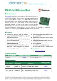
Tin Whiskers<br />
Tin Whiskers<br />
What are they?<br />
z<br />
Whiskers are thin fibres of tin that grow<br />
apparently spontaneously from electroplated tin surfaces<br />
z Tin whiskers can cause short circuits and have caused<br />
several satellites, missiles, heart pacemakers and a nuclear<br />
power station to fail<br />
z Electroplated tin coatings are used on most component<br />
terminations to aid soldering and to provide corrosion<br />
resistance<br />
z<br />
z<br />
Whiskers of several mm are possible although ~<br />
100µm is more common.<br />
Only long whiskers cause failures.<br />
Causes of Tin Whiskers<br />
z Whiskers are caused by compressive stresses in tin coatings<br />
z<br />
Stresses are induced by:<br />
• Irregular intermetallic crystals that grow at copper /<br />
tin interfaces<br />
• Due to stress induced by thermal expansion mis-match<br />
between layers of coatings<br />
• Due to formation of bulky oxides between tin grains in<br />
humid environments<br />
SEM image of tin whiskers taken by ERA Technology Ltd<br />
Prevention of Tin Whiskers<br />
z<br />
z<br />
z<br />
A lot of research has been carried out into the causes<br />
and prevention<br />
iNEMI has published guidance<br />
• http://thor.inemi.org/webdownload/projects/ese/tin_<br />
whiskers/Pb-Free_Finishes_v4.pdf<br />
• Risk should be small if this is followed but:<br />
Equipment manufacturers buy pre-plated components from<br />
suppliers and have no influence over production process<br />
• Test methods are available but<br />
z These take at least 3 months – no use for QA<br />
z Equipment manufacturers need a whisker<br />
mitigation strategy:<br />
• Approved supplier list for COTS components<br />
• Document coating specification for custom made parts<br />
• Design requirements<br />
• Conformal coatings<br />
© 2010 Premier Farnell plc Permission is granted for reproduction in whole<br />
or in part provided Premier Farnell plc is credited.<br />
7<br />
Measures to avoid Tin Whiskers<br />
z<br />
Whisker risk very low if the following are used:<br />
1. Use Ni/Pd/Au termination coatings (no risk but an<br />
uncommon coating)<br />
2. Use tin/lead terminations (extremely low risk but<br />
infrequently available)<br />
3. Thin matte tin on copper with a non-porous nickel<br />
barrier layer (very low risk)<br />
4. Bake matte tin on copper at 150°C for 1 hour within 24<br />
hours of plating (no good later than this). Very low risk but<br />
only a few component manufacturers do this<br />
5. Melt electroplated tin – this usually prevents whiskers but<br />
the high temperature may cause heat damage.<br />
Hot dipped terminations are OK<br />
How to avoid Tin Whiskers<br />
z<br />
Do not use SnCu plating but SnAg is OK<br />
z Avoid alloy 42 lead-frame components or other low TCE<br />
materials if there is a choice<br />
z Whisker resistant matte tin plating processes are new, not<br />
all electroplaters use them, check that they do and that<br />
operating procedures are followed<br />
z Matte tin is usually less susceptible to whiskers although<br />
whisker resistant bright tin is available<br />
z SnBi termination coatings are OK but ensure
Replacements for Standard Solder<br />
There is no “drop-in” replacement for standard tin/lead solder.<br />
All lead-free alloys are different. (M.pt. = melting point)<br />
Alloy composition M.p.t. °C Comments<br />
Eutectic tin/lead solder 183 Included for comparison. Good wetting and low melting temperature<br />
Sn0.7Cu 227 Used for wave soldering applications (known as 99C), high melting<br />
temperature and<br />
wetting inferior to SnAg<br />
Sn3.5Ag 221 Used as high temperature solder,<br />
wetting inferior to SnAgCu<br />
Sn3.5Ag0.7Cu (and variations<br />
on this)<br />
© 2010 Premier Farnell plc Permission is granted for reproduction in whole<br />
or in part provided Premier Farnell plc is credited.<br />
217 Most widely used lead-free alloy.<br />
Various percentages of silver and copper<br />
are used. Melting<br />
temperature 34°C higher than tin/lead and<br />
inferior wetting<br />
SnAgBi alloys (some with Cu) Ca. 210 -215 Better wetting properties than SnAgCu but<br />
must not be used with lead.<br />
Mainly used as solder pastes<br />
but has been used for wave soldering,<br />
mainly in Japan.<br />
Wire not available<br />
Sn9Zn 198 Needs special flux and is susceptible to corrosion<br />
Sn8Zn3Bi Ca. 191 Used by several Japanese manufacturers<br />
where heat sensitive components are used.<br />
Difficult to use<br />
58Bi42Sn 138 Low melting point, hard, brittle alloy<br />
8
Reliability issues with lead-free solders<br />
The main differences between lead-free and tin/lead alloys<br />
that need to be understood to avoid reliability issues are:<br />
Higher melting temperature<br />
Lead-free alloy soldering temperature is higher (30°C - 40°C),<br />
which can lead to a variety of defects such as:<br />
z<br />
z<br />
z<br />
z<br />
Thermal fatigue of solder joints - not well understood,<br />
research is on-going<br />
Tin-whiskers from electroplated tin termination coatings -<br />
research is on-going<br />
Delamination of multi-layer PCBs<br />
Damage to plated through holes -<br />
especially with narrow holes in thicker laminate<br />
z PCB warping -<br />
can damage components, cause open circuits,<br />
misalignment<br />
z IC packages are more susceptible to “pop-corn” failure.<br />
The IPC/JEDEC-020B Moisture Sensitivity Level for<br />
components with<br />
lead-free soldering can be 1 or 2 levels lower.<br />
z Damage to heat sensitive components. Processes<br />
improving but check upper temperature limit in<br />
manufacturers datasheet<br />
© 2010 Premier Farnell plc Permission is granted for reproduction in whole<br />
or in part provided Premier Farnell plc is credited.<br />
9<br />
Wetting<br />
of most lead-free solders is inferior to tin/lead.<br />
z<br />
z<br />
Tin coatings behave differently to tin/lead, even with tin/<br />
lead solder<br />
Correct choice of flux important.<br />
z It is more important with lead-free that component<br />
terminations and solderable surfaces are clean and oxidefree<br />
z Use the correct temperature profile. If the temperature<br />
rises too slowly due to poor temperature control or<br />
insufficient power, surfaces will oxidise making solder<br />
wetting more difficult. Beware of too rapid temperature<br />
rise as this can damage some components and PCBs due<br />
to thermal shock.<br />
z The surface tension of lead-free solders is higher than tin/<br />
lead solders. This limits solder spread as well as increasing<br />
the risk of “tomb-stoning”.<br />
Example of tomb-stoning<br />
Tomb-stoning can be prevented by alignment of the<br />
component perpendicular to the direction of the conveyer,<br />
using a paste with a wider pasty range, ensuring all surfaces<br />
have good solderability<br />
Components: Typical maximum temperatures<br />
Aluminium electrolytic capacitor - max. temp. depends on size 240°C -250°C<br />
Tantalum capacitor - various types 220°C -260°C<br />
MLCC ramp rate more important 240°C -260°C<br />
Film capacitor 230°C -300°C<br />
Surface mount relay 226°C -245°C<br />
Crystal oscillator 235°C -245°C<br />
Connector - depends on type of plastic used 220°C -245°C<br />
LED - may function but light output affected 240°C -280°C<br />
Ball Grid Array & Chip Scale Packaged devices 220°C -240°C<br />
Other ICs 245°C -260°C
Lead-Free Soldering<br />
Hand soldering<br />
z<br />
z<br />
z<br />
This is relatively straightforward and trials with samples<br />
of wire are easy to carry out.<br />
Greatest difficulty is with large thermal mass components.<br />
Many lead-free SnCu, SnAgCu, SnAg wire products<br />
available.<br />
z Alloys with bismuth not generally available as it is brittle<br />
and difficult to make into wire (can be made as “specials”<br />
but more expensive).<br />
z<br />
z<br />
z<br />
Need slightly higher soldering iron tip temperature.<br />
More aggressive solders and fluxes will shorten tip life -<br />
10°C rise could halve tip life.<br />
Longer pre-heat needed and wetting will take longer<br />
unless very high temperature is used.<br />
z Older style soldering irons have poor temperature control<br />
- can result in overheating<br />
(large temperature cycle).<br />
z<br />
z<br />
New soldering iron equipment has much better<br />
temperature control<br />
“Lead-Free” iron tips available.<br />
z Frequently too-high a temperature is used with SnPb for<br />
fast wetting - operators in these cases may be able to use<br />
the same temperature with lead-free wire.<br />
z To find optimum tip temperature:- start at 350°C, reduce<br />
temperature until poor results occur then increase by<br />
10°C (or increase until good results are obtained).<br />
Wave soldering<br />
z<br />
z<br />
z<br />
z<br />
z<br />
z<br />
Lead-free solders can damage steel parts - contact<br />
machine supplier for advice.<br />
Higher temperature required.<br />
Need to choose suitable flux.<br />
Some components may be damaged if they pass through<br />
the wave.<br />
Drossing rate higher - consider using nitrogen over wave.<br />
Check bath composition initially, especially if some tin/<br />
lead terminated components used.<br />
© 2010 Premier Farnell plc Permission is granted for reproduction in whole<br />
or in part provided Premier Farnell plc is credited.<br />
10<br />
Surface mount<br />
z<br />
Forced air convection heating needed for better<br />
temperature control.<br />
z Minimise peak temperature with good temperature<br />
control and many heat zones. Ovens may need to be<br />
longer with throughput lower to achieve good results.<br />
z A controlled cooling rate is advisable as some component<br />
coatings can crack if cooled too slowly. Too rapid cooling<br />
can damage certain brittle components such as MLCCs.<br />
z<br />
Nitrogen helps but is not essential.<br />
z Choose optimum paste by comparative testing with<br />
realistic test PCBs. Test each paste over an eight-hour<br />
shift. This can be carried with 12 PCBs:<br />
z<br />
z<br />
z<br />
z<br />
z<br />
z<br />
z<br />
Print 4 (no kneading), then place components, measure<br />
tack on 2 of these.<br />
1 PCB wait 1 hour then reflow.<br />
1 PCB wait 3 hours then reflow.<br />
Wait 6 hours, then place components, measure tack, then<br />
reflow.<br />
Repeat with 4 more after 1 hour.<br />
Repeat tests.<br />
Repeat with 4 more after 1 hourRepeat tests.<br />
Note:<br />
Soldering iron tips have a shorter life with lead-free than<br />
tin-lead for three reasons:<br />
1. Higher temperature increases tip coating dissolution<br />
rate<br />
2. Lead-free uses more corrosive fluxes<br />
The tip coating is iron and this reacts with tin faster<br />
3.<br />
(to form on intermetallic) than with tin-lead
Lead-Free Soldering<br />
PCB coatings<br />
traditional tin/lead hot air level (HASL) coatings cannot be used.<br />
Alternatives include:<br />
PCB Coating Limitations<br />
Lead-free HASL Need new equipment, pre-bake boards<br />
Nickel/gold (ENIG) Gives good protection and solderability for up to 1 year but most<br />
expensive option<br />
Organic solderability preservative Low cost option, protection for up to 6 months, very easily<br />
damaged<br />
Immersion silver Good compromise but tarnishes (sulphides)<br />
Immersion tin Good compromise but deteriorates in warm or humid conditions<br />
Inspection<br />
Lead-free solder joints appear different to tin/lead and therefore training may be required so that operators can recognise good<br />
and poor solder joints. The criteria in IPC - 610C, although originally written for tin/lead should also apply to lead-free solder<br />
© 2010 Premier Farnell plc Permission is granted for reproduction in whole<br />
or in part provided Premier Farnell plc is credited.<br />
Examples of tin lead solder joints<br />
Examples of Tin/Silver/Copper solder joints<br />
11
Rework and repair<br />
Spare parts for the repair of equipment put onto the market before 1st July 2006 are not within the scope of the <strong>RoHS</strong> <strong>Directive</strong>.<br />
Therefore these spares may legally contain the six restricted substances. By inference therefore, spare parts used for the repair of<br />
equipment put onto the market after this date, must not contain restricted substances.<br />
The same types of rework tools that are used for tin/lead can be used for lead-free solders. It is advisable however to avoid mixing<br />
alloys so wherever possible, repair using the same solder as was originally used. Some combinations can give very poor reliability,<br />
in particular lead and bismuth.<br />
The temperature will need to be high so there is a greater risk of damage to heat sensitive components and the PCB, including<br />
high aspect ration plated through holes.<br />
More aggressive fluxes may be required. These can cause SIR, corrosion and dendrites problems.<br />
No. Defect Cause Solution<br />
1 Poor wetting i. Unsuitable flux<br />
ii. Surfaces oxidised or contaminated<br />
iii. Poor temperature control<br />
2 No wetting Part not hot enough<br />
Insufficient heating power for part to reach<br />
solder melting temperature in a short enough<br />
time<br />
3 PCB delamination Moisture within laminate and incorrect<br />
temperature profile<br />
© 2010 Premier Farnell plc Permission is granted for reproduction in whole<br />
or in part provided Premier Farnell plc is credited.<br />
12<br />
i. Use different flux<br />
ii. Ensure surfaces are clean and oxide free - do<br />
not use parts beyond their use-by dates<br />
Rotate stocks of components and PCBs<br />
iii. Use equipment with better temperature<br />
control<br />
Use equipment with good temperature control<br />
and sufficient power<br />
Increase pre-heat time/temp. to dry PCB before<br />
reflow<br />
4 PCB warping High reflow temperature Reduce reflow temperature<br />
Use high Tg laminate<br />
Re-design to eliminate stresses during reflow<br />
5 Pop-corning of ICs Moisture within package Check moisture sensitivity level of component<br />
for lead-free processes. May need to store in dry<br />
environment or bake before use.<br />
6 Cracked PTH Stresses on copper due to high TCE of laminate<br />
Drilling defects increase risk<br />
7 Damaged<br />
components<br />
Re-design with thinner laminate, larger diameter<br />
PTH, increase copper thickness, use low z-axis<br />
TCE laminate. Replace drill bits more frequently<br />
Exceeded maximum temperature Use alternative components if available<br />
Re-design to avoid heat sensitive components<br />
Use lower reflow temperature (may need new<br />
equipment)
Rework and repair<br />
Trouble shooting guide continued<br />
No. Defect Cause Solution<br />
8 Shorts on PCB<br />
(bridging)<br />
9 Excessive number of<br />
solder balls<br />
Lead-free solders have higher surface tension<br />
than lead solder<br />
13<br />
Use hot-air knife after reflow<br />
Increase time above solder melting temperature<br />
Use different flux<br />
Incorrect solder reflow profile, incorrect flux Modify profile, use more active flux<br />
10 Volds in solder joints Trapped gas from coatings or flux Increase time of pre-heat and time above solder<br />
melting temperature.<br />
11 Solder bonds fracture<br />
easily after reflow<br />
12 Short circuits occur in<br />
field<br />
13 Open circuits occur in<br />
field due to thermal<br />
fatigue<br />
Thick and brittle intermetallic later formed Decrease maximum temperature and time above<br />
solder melting temperature.<br />
i. Tin whiskers form after persion service<br />
ii. Dendrites<br />
i. High strain on solder joints<br />
ii. Poor solder wetting<br />
© 2010 Premier Farnell plc Permission is granted for reproduction in whole<br />
or in part provided Premier Farnell plc is credited.<br />
i. Specify coatings with low susceptibility to tin<br />
whiskers<br />
ii. Use less active flux or clean to remove flux<br />
residues.<br />
i. Redesign to minimise joint strain<br />
ii. Improve wetting - see 1.
Proposals<br />
SEPTEMBER 2009 PROPOSALS<br />
Following discussions between EU Member States and the<br />
Council of Ministers new proposals were put forward by<br />
Sweden, who owned the EU presidency at that time, to amend<br />
the scope of the <strong>RoHS</strong> <strong>Directive</strong>.<br />
Under the proposals the scope would change to encompass<br />
all electrical and electronic equipment unless specifically<br />
excluded. Currently there are 8 product categories with<br />
binding examples of what products fall within scope. A<br />
recast, published in December 2008, also proposed the<br />
phased in addition of categories 8 and 9 (medical devices and<br />
monitoring and control instruments).<br />
Annex I (the 10 broad product categories) and Annex II<br />
(binding list of product examples) were deleted from the text<br />
of the <strong>RoHS</strong> recast and would sit, as before, within the WEEE<br />
<strong>Directive</strong> although Annex II was referred to as indicative as<br />
opposed to a binding list.<br />
There were new exclusions from the <strong>RoHS</strong> text such as largescale<br />
stationary industrial tools (LSIT) but the impact of the<br />
revised proposals was clearly to include products that are not<br />
currently in scope.<br />
It was also proposed to delete Annex III that listed four<br />
substances - BBP. DBP, DEHP and HBCDD for priority<br />
assessment, leading to possible restrictions.<br />
However, the Commission intended to adopt a methodology<br />
for the review of the restricted substances in Annex IV (the<br />
original 6 possible, but unlikely) and new substances where<br />
deemed necessary in the future, based on the process set out<br />
in Articles 69 to 72 of the REACH Regulations.<br />
This would look to review a substance used in EEE, or the<br />
waste derived from it, that poses a hazard to human health or<br />
the environment that is not adequately controlled.<br />
However, industry would be interested in the scope, where any<br />
product that relies on electricity to function could be included<br />
as well as the status of some of the grey area products. No<br />
longer will there be the “is it in scope or is it out” issues<br />
as with, for example, semiconductor development tools at<br />
present, as everything will be within scope unless specifically<br />
excluded.<br />
<strong>RoHS</strong> was previously unclear, especially for fixed installations,<br />
and it is probable that these proposals were an attempt to<br />
resolve this. However, “equipment that is part of equipment<br />
that is out of scope is itself out of scope” remained in the text<br />
so uncertainty was likely to continue.<br />
NOVEMBER 2009 DRAFT RECAST<br />
A draft proposal for the recast of the <strong>RoHS</strong> <strong>Directive</strong> has been<br />
published by the European Parliament (EP).<br />
Among the proposed changes is to include all electrical<br />
products. The approach would be to add an 11th product<br />
category to the existing 10. The scope of the new category<br />
© 2010 Premier Farnell plc Permission is granted for reproduction in whole<br />
or in part provided Premier Farnell plc is credited.<br />
14<br />
would simply be “other electrical and electronic equipment<br />
not covered by any of the categories 1-10”.<br />
In addition, the current exclusion of large-scale stationary<br />
industrial tools (LSIT) has been deleted and so all EEE<br />
including manufacturing production line equipment would be<br />
in scope.<br />
Equipment covered by the new category 11 would come into<br />
scope in July 2014.<br />
The controversial “equipment that is part of another type of<br />
equipment that does not fall in scope and can only fulfil its<br />
function if it is part of that equipment” is proposed to change<br />
to “part of stationary installations or transport equipment<br />
that is not electrical or electronic equipment”<br />
This would bring into scope all electrical products used in<br />
building and transport (unless covered by other legislation<br />
such as the ELV <strong>Directive</strong>), all “fixed installations” and<br />
electrical parts in aircraft, trains, ships and commercial<br />
vehicles.<br />
The list of restricted substances has been increased<br />
considerably under the proposals and includes PVC,<br />
chlorinated plasticisers, organohalogens, flame retardants<br />
and the phthalates BBP, DBP and DEHP.<br />
These will not be imposed on products in categories 8, 9 or<br />
the new category 11 until the Commission has investigated and<br />
proposed a date.<br />
The exemption for spare parts will be limited to 42 months<br />
after the amended directive enters into force. However, spare<br />
parts will have an exemption where the equipment benefited<br />
from an exemption that has subsequently expired.<br />
The substances mentioned above will also be restricted in<br />
spare parts.<br />
On exemptions themselves the EP proposes that the expiry<br />
period is “up to” 4 years and not the current 4 years.<br />
The Commission will decide within 6 months of an exemption<br />
expiring whether or not it will be renewed. Grace periods<br />
will be allowed but for no more than 18 months after the<br />
exemption expires.<br />
The Commission proposes to change the definition of<br />
homogeneous materials which would now align itself more<br />
along the lines of China <strong>RoHS</strong>.<br />
The definition states that a homogeneous material is one<br />
that consists of only one material throughout, a combination<br />
of multiple materials that can not be mechanically disjointed<br />
into different materials or, finally, a surface coating.<br />
These proposals will be debated until late 2010/early 2011 but,<br />
once again, could have a significant impact on industry not<br />
least leading to more substance data collection on products<br />
falling within scope and several new restricted substances.
June 2010 vote<br />
June 2010 vote<br />
The <strong>RoHS</strong> directive is currently being reviewed with extensive<br />
discussions by the Council of Ministers and the European<br />
Parliament. The Rapporteur of the European Parliament<br />
environment committee had proposed that all brominated<br />
and chlorinated flame retardants and PVC should be banned<br />
by <strong>RoHS</strong>. However, due to overwhelming opposition, this<br />
has been dropped and replaced by a requirement that the<br />
European Commission consider as a high priority whether it<br />
is necessary to restrict these substances as well as several<br />
others.<br />
Green Groups have been lobbying for these substances to<br />
be banned with support from some consumer electronics<br />
manufacturers whereas most manufacturers are opposed to<br />
these restrictions. So why are there such diverse opinions on<br />
these substances?<br />
Green groups incorrectly claim that most organobromine<br />
and organochlorine compounds are hazardous. When the<br />
research data is fully evaluated, there is no evidence of<br />
harmful effects for the majority of these substances and only<br />
a few have been found to be hazardous and these are already,<br />
or will soon be, restricted by European Union (EU) legislation.<br />
When assessing the toxicity of substances, it is important<br />
that all data is considered and that each study is evaluated to<br />
determine if the research was carried out properly and also,<br />
it is realistic - this is not always the case. It is not uncommon<br />
for some organisations to select the research that suits<br />
their aims rather than provide full unbiased assessments<br />
of all research as is done by the few comprehensive EU risk<br />
assessments that have been carried out. Green groups are<br />
correct however when they say that uncontrolled burning<br />
of plastics that contain these substances and also PVC can<br />
cause the emission of very toxic and carcinogenic dioxins and<br />
furans although these substances are also emitted from home<br />
refuse burning, metals manufacture and wood preservatives<br />
as well as the open burning of waste. Problems occur if waste<br />
electrical equipment is recycled in developing countries by<br />
burning on open fires as this emits dangerous levels of dioxins<br />
and furans. Banning these substances in the EU only would<br />
have almost no benefit. Firstly, it will be many years before<br />
the existing stock of equipment that contains organohalogens<br />
reaches end-of-life, secondly, in Asia, most of the e-waste<br />
currently being recycled is domestic and so EU legislation<br />
would have no effect and thirdly, burning halogen-free<br />
plastics on open fires emits different dangerous substances,<br />
in particular polycyclic aromatic hydrocarbons which are also<br />
toxic and carcinogenic. Clearly a different solution is needed.<br />
© 2010 Premier Farnell plc Permission is granted for reproduction in whole<br />
or in part provided Premier Farnell plc is credited.<br />
15<br />
Some consumer electronics manufacturers have policies<br />
of not using halogenated flame retardants or PVC. This is<br />
partly in response to pressure from green groups and may<br />
also give a marketing advantage – a “green” image. These<br />
manufacturers would benefit from these substances being<br />
banned as this would make it easier for them to force their<br />
suppliers to change the materials used in components that<br />
they use.<br />
Most manufacturers however are opposed to banning these<br />
substances. The health and environmental benefits of such<br />
as ban are uncertain and appear to be limited whereas the<br />
cost of substitution would be extremely high. A recent report<br />
found that the cost of replacing PVC could be as much as<br />
€20 billion per year although this may be an over-estimate.<br />
Many of the possible alternatives have not been tested as<br />
extensively as the most common organohalogen flame<br />
retardants and PVC and although most are probably safe, this<br />
cannot be known with certainty.<br />
There is no doubt that substitutes exist for PVC and for<br />
organobromine and organochlorine flame retardants for most<br />
but not all applications. However substitution is often not<br />
straightforward as these are seldom drop in replacements.<br />
Plastics will usually need to be completely reformulated<br />
and their properties may be different and reliability could<br />
be affected in some cases. Substitutes will usually be more<br />
expensive - if they were cheaper then manufacturers would<br />
already have changed! Is there a real benefit from not using<br />
these substances? This is currently far from certain. It<br />
seems likely that it will be the responsibility of the European<br />
Commission to answer this question by carrying out an impact<br />
assessment to determine whether the very high cost justifies<br />
the benefit, whatever these turn out to be from their study.
June 2010 vote<br />
Other issues<br />
As the proposal to ban additional substances has been<br />
dropped by the European Parliament environment committee<br />
(apart from two nanomaterials), there may be enough<br />
agreement between the European Parliament and Council<br />
of Ministers on the main <strong>RoHS</strong> issues for them to agree on<br />
a recast directive before the end of 2010. The main changes<br />
would include:<br />
Open scope with the exclusion of transport, large-scale<br />
stationary industrial tools and renewable energy technology.<br />
The exclusion of fixed installations is also possible but there is<br />
less agreement on this issue.<br />
Additional substance restrictions would be introduced by<br />
the European Commission and not as part of the recast<br />
process. This will use a procedure based on the one used for<br />
REACH substance restrictions but taking account of waste<br />
disposal issues. The exact procedure is not yet decided but<br />
will be based on proven risk (not only hazards) and on impact<br />
assessments that consider all potential alternatives.<br />
Changes to the exemptions procedure are also likely but exact<br />
details are subject to continued negotiation.<br />
With thanks to Dr. Paul Goodman, ERA Technology trading as<br />
Cobham <strong>Technical</strong> Services.<br />
© 2010 Premier Farnell plc. Permission is granted for reproduction in whole or in part providing Premier Farnell plc is<br />
credited. Written in collaboration with ERA Technology trading as Cobham <strong>Technical</strong> Services (www.era.co.uk/rfa)<br />
Version 2 May 2010<br />
Written in callobaration with ERA Technology trading as Cobham <strong>Technical</strong> Services (www.era.co.uk/rfa)<br />
16<br />
Please note:<br />
The information contained in this guide is of a general nature<br />
and is not intended to address the circumstances of any<br />
particular individual or entity. Although we endeavour to<br />
provide accurate and timely information, there can be no<br />
guarantee that such information is accurate as of the date it<br />
is received or that it will continue to be accurate in the future.<br />
No one should act on such information without appropriate<br />
professional advice after a thorough examination of the<br />
particular situation.<br />
BAU: 43907