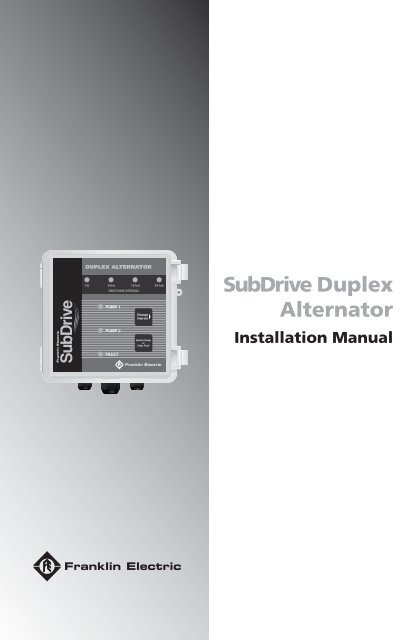
SubDrive Duplex Alternator
SubDrive Duplex Alternator
SubDrive Duplex Alternator
You also want an ePaper? Increase the reach of your titles
YUMPU automatically turns print PDFs into web optimized ePapers that Google loves.
<strong>SubDrive</strong> <strong>Duplex</strong><br />
<strong>Alternator</strong><br />
Installation Manual
<strong>SubDrive</strong> <strong>Duplex</strong> <strong>Alternator</strong><br />
Contents<br />
Descriptions and Features. . . . . . . . . . . . . . . . . . . . . . . . . . . . . . . . . . . . . . . 3<br />
Included Items . . . . . . . . . . . . . . . . . . . . . . . . . . . . . . . . . . . . . . . . . . . . . . . . 4<br />
How It Works. . . . . . . . . . . . . . . . . . . . . . . . . . . . . . . . . . . . . . . . . . . . . . . . 5-6<br />
Before Getting Started . . . . . . . . . . . . . . . . . . . . . . . . . . . . . . . . . . . . . . . . . . 6<br />
Controller Location Selection . . . . . . . . . . . . . . . . . . . . . . . . . . . . . . . . . . . . 7<br />
Quick Reference Guide . . . . . . . . . . . . . . . . . . . . . . . . . . . . . . . . . . . . . . . . . 8<br />
Installation Procedure . . . . . . . . . . . . . . . . . . . . . . . . . . . . . . . . . . . . . . . . . . 9<br />
Wiring Connections . . . . . . . . . . . . . . . . . . . . . . . . . . . . . . . . . . . . . . . . 10-13<br />
Start-Up and Operation . . . . . . . . . . . . . . . . . . . . . . . . . . . . . . . . . . . . . 13-14<br />
Mounting Dimensions . . . . . . . . . . . . . . . . . . . . . . . . . . . . . . . . . . . . . . . . . 15<br />
Accessories. . . . . . . . . . . . . . . . . . . . . . . . . . . . . . . . . . . . . . . . . . . . . . . . . . 15<br />
Diagnostic Fault Codes . . . . . . . . . . . . . . . . . . . . . . . . . . . . . . . . . . . . . . . . 16<br />
Specifi cations . . . . . . . . . . . . . . . . . . . . . . . . . . . . . . . . . . . . . . . . . . . . . . . . 17<br />
Tables<br />
1. <strong>SubDrive</strong> and MonoDrive Models . . . . . . . . . . . . . . . . . . . . . . . . . . . . . . . 3<br />
Figures<br />
1. Mounting Screws . . . . . . . . . . . . . . . . . . . . . . . . . . . . . . . . . . . . . . . . . . . . 9<br />
2. Drive Sensor Cable Connections . . . . . . . . . . . . . . . . . . . . . . . . . . . . . . 10<br />
3. Pressure Sensor Connections. . . . . . . . . . . . . . . . . . . . . . . . . . . . . . . . . 11<br />
4. Alarm Connections. . . . . . . . . . . . . . . . . . . . . . . . . . . . . . . . . . . . . . . . . . 13
<strong>SubDrive</strong> <strong>Duplex</strong> <strong>Alternator</strong><br />
3<br />
Table 1: <strong>SubDrive</strong> and MonoDrive Models<br />
Model Name Part Number Use with <strong>SubDrive</strong> Series<br />
<strong>SubDrive</strong> <strong>Duplex</strong><br />
<strong>Alternator</strong><br />
5850012000 5870203380D <strong>SubDrive</strong>75 NEMA 1<br />
5870203380Q <strong>SubDrive</strong>75 NEMA 1 QP<br />
5870203383D <strong>SubDrive</strong>75 NEMA 3R<br />
5870203383Q <strong>SubDrive</strong>75 NEMA 3R QP<br />
5870203384 <strong>SubDrive</strong>75 NEMA 4<br />
5870204150 <strong>SubDrive</strong>150 NEMA 1<br />
5870204150Q <strong>SubDrive</strong>150 NEMA 1 QP<br />
5870204154 <strong>SubDrive</strong>150 NEMA 4<br />
5870206300 <strong>SubDrive</strong>300 NEMA 4<br />
5870203113 MonoDrive<br />
5870204110 MonoDriveXT<br />
5870203110 MonoDrive Universal<br />
Note: <strong>SubDrive</strong> <strong>Duplex</strong> <strong>Alternator</strong> will work with any combination of the listed<br />
Franklin Electric <strong>SubDrive</strong>s/MonoDrives.<br />
Descriptions and Features<br />
The Franklin Electric <strong>SubDrive</strong> <strong>Duplex</strong> <strong>Alternator</strong> allows for two Franklin Electric<br />
<strong>SubDrive</strong> units to operate on the same water system and share the work load<br />
equally. The <strong>Alternator</strong> will alternate between the two <strong>SubDrive</strong> units when the<br />
defi ned amount of run time has been reached. The <strong>Alternator</strong> is specifi cally<br />
designed for use with Franklin Electric <strong>SubDrive</strong> products (see Table 1 above).<br />
Key features of the <strong>Alternator</strong> include the following:<br />
• Works with entire <strong>SubDrive</strong> • Manual override push-button<br />
product family<br />
• Alarm circuit contacts<br />
• Selectable alternate timing • NEMA 4 enclosure<br />
• Pump status indicator lights • Low voltage wiring connections<br />
• Fault detection<br />
• Fail safe operation
Included Items<br />
D<br />
B<br />
C<br />
A. Controller Unit<br />
B. Sensor Cable (Pressure Sensors, 4-conductor)<br />
C. Sensor Cable (<strong>SubDrive</strong>s, 2-conductor) X2<br />
D. Mounting Brackets<br />
E. Outdoor Rated 120 VAC/12 VAC Transformer<br />
F. Transformer Output Cable<br />
G. Rubber Plug<br />
H. Installation Manual<br />
<strong>SubDrive</strong> <strong>Duplex</strong> <strong>Alternator</strong><br />
A<br />
E<br />
F<br />
<strong>SubDrive</strong> <strong>Duplex</strong><br />
<strong>Alternator</strong><br />
Installation Manual<br />
H<br />
G<br />
4
<strong>SubDrive</strong> <strong>Duplex</strong> <strong>Alternator</strong><br />
5<br />
How It Works<br />
The Franklin Electric <strong>SubDrive</strong> <strong>Duplex</strong> <strong>Alternator</strong> is designed to be part of two<br />
independent <strong>SubDrive</strong> systems. Below is an example of a typical <strong>Alternator</strong><br />
System.<br />
Pressure Sensor<br />
Cables<br />
Pressure Sensors<br />
Pressure Tank<br />
(see Quick Reference Guide on<br />
pg. 8 for more detail on plumbing)<br />
Alternating <strong>SubDrive</strong> Systems<br />
The <strong>Alternator</strong> controls which drive is running the system by determining which<br />
pressure sensor each drive sees. The two pressure sensors in the system must<br />
have at least a 3 psi differential. The drive that uses the high set sensor will be in<br />
control of supplying water to the system. The other drive will be on the lower set<br />
sensor and will act as a backup. In the event that the primary drive cannot keep<br />
up with the water demand, the backup drive will automatically start and provide<br />
additional water. After the primary drive has reached its defi ned amount of run<br />
time, the <strong>Alternator</strong> will interchange the pressure sensors, thus causing the two<br />
drive units to switch roles.<br />
System Diagnostics<br />
<strong>Duplex</strong> <strong>Alternator</strong><br />
<strong>SubDrive</strong> Pressure<br />
Sensor Connections<br />
To Power Supply<br />
<strong>SubDrive</strong> 1<br />
To Power Supply<br />
<strong>SubDrive</strong> 2<br />
Motor Cables<br />
In addition to alternating the two drive systems, the <strong>Alternator</strong> monitors the<br />
two systems to see if they are meeting the water demand as expected. If a<br />
system is not meeting the water demand as expected, the <strong>Alternator</strong> will lock<br />
the remaining system in as the primary system, declare a fl ash code indicating<br />
what kind of fault was found, close the alarm contacts, and not allow further<br />
alternation until the fault is cleared.
Fail Safe Operation<br />
<strong>SubDrive</strong> <strong>Duplex</strong> <strong>Alternator</strong><br />
The <strong>Alternator</strong> is designed so that both <strong>SubDrive</strong> units are always linked to one<br />
pressure sensor or the other. If the <strong>Alternator</strong> should fail, the system will turn into<br />
a lead-lag system without the alternate function. Therefore, water will still<br />
be delivered even if the <strong>Alternator</strong> should fail.<br />
Additional Features<br />
The <strong>Alternator</strong> has a manual override button for selecting which <strong>SubDrive</strong> unit<br />
should be the primary system. The <strong>Alternator</strong> also has four different (push<br />
button) selectable timing modes ranging from 1 hour to 24 hours. These timing<br />
modes are based on the run time of the <strong>SubDrive</strong> unit. When a unit has run<br />
the selected amount of time, the <strong>Alternator</strong> automatically interchanges the<br />
primary and backup systems. In addition, the <strong>Alternator</strong> can be used with any<br />
combination of <strong>SubDrive</strong> products from Franklin Electric; one model fi ts all!<br />
Before Getting Started<br />
▲ ! WARNING<br />
For the indoor/outdoor transformer note the following:<br />
Risk of fi re. If installation involves running wiring through a building<br />
structure, special wiring methods are needed. Consult a qualifi ed electrician.<br />
Not for use with dimmers.<br />
▲ ! ATTENTION<br />
This equipment should be installed by technically qualifi ed personnel.<br />
Installation must comply with Franklin Electric’s recommendations, national<br />
and local electrical codes. Failure to do so may result in electrical shock,<br />
fi re hazard, unsatisfactory performance, or equipment failure. Installation<br />
information is available through pump manufacturers and distributors, or<br />
directly from Franklin Electric at our toll-free number 1-800-348-2420.<br />
▲ ! CAUTION<br />
Use the <strong>SubDrive</strong> <strong>Duplex</strong> <strong>Alternator</strong> only with Franklin Electric <strong>SubDrive</strong><br />
units as specifi ed in this manual (see Table 1). Use of this unit with Variable<br />
Frequency Drives (VFDs) from other manufacturers may result in damage to<br />
both sets of electronics.<br />
6
<strong>SubDrive</strong> <strong>Duplex</strong> <strong>Alternator</strong><br />
7<br />
Controller Location Selection<br />
The following recommendations will help in the selection of the proper location<br />
of the <strong>Alternator</strong> unit.<br />
1. A tee is recommended for mounting the two pressure sensors at<br />
one junction. If a tee is not used, the pressure sensors should<br />
be located within 6 feet (1.8 meters) of the pressure tank to<br />
minimize pressure fl uctuations. The distance between the<br />
pressure sensors should be kept to a minimum. There should be<br />
no elbows between the tank and the pressure sensors.<br />
2. The unit should be mounted on a sturdy supporting structure<br />
such as a wall or supporting post.<br />
3. When installed properly, the <strong>Alternator</strong> enclosure is suitable for<br />
indoor or outdoor installations (see Installation Procedure section<br />
for details pg. 9).<br />
4. The <strong>Alternator</strong> should only be mounted with the wiring end<br />
oriented downward. The controller should not be placed in<br />
direct sunlight.<br />
5. The mounting location should have access to 115 VAC electrical<br />
supply. For outdoor installations the indoor/outdoor transformer<br />
must be connected to a GFCI outlet and follow all National,<br />
State, and Local electrical codes. Ensure that requirements of<br />
NEC 406.8 are met.<br />
6. To assure maximum weather protection, the unit must be<br />
mounted vertically with the cover snaps engaged.<br />
Sensor Cables from<br />
Pressure Sensors<br />
CORRECT INCORRECT<br />
Power Supply<br />
from Transformer<br />
Sensor Cables to Drives<br />
Sensor Cables to Drives<br />
Power Supply<br />
from Transformer<br />
Sensor Cables from<br />
Pressure Sensors
Quick Reference Guide <strong>SubDrive</strong> <strong>Duplex</strong> <strong>Alternator</strong><br />
Drive 2<br />
Drive 1<br />
Sensor Cable<br />
Supplied<br />
Tank Pre-charge<br />
Inflation Valve<br />
1 2 1 2<br />
1 2 1 2<br />
PS-HI PS-LO SD1 SD2<br />
PRESSURE 12 VAC<br />
DRIVES<br />
ALARM SENSORS<br />
24VAC 1A MAX<br />
24 VDC 0.5A MAX<br />
<strong>SubDrive</strong> <strong>Duplex</strong> <strong>Alternator</strong><br />
Pressure<br />
Sensor<br />
Pressure<br />
Sensor<br />
Pressure Gauge<br />
Motor Cable<br />
To<br />
Power<br />
Source<br />
To<br />
Power<br />
Source<br />
Drive Sensor<br />
Cables<br />
Motor Cable<br />
(To Residence)<br />
Drain Valve<br />
Pressure<br />
Relief Valve<br />
Discharge into<br />
drain rated for<br />
max pump output<br />
at relief pressure.<br />
Pump 1 Pump 2<br />
Motor 2<br />
Motor 1<br />
GFCI Outlet<br />
Outdoor outlet cover<br />
for outdoor use<br />
8
<strong>SubDrive</strong> <strong>Duplex</strong> <strong>Alternator</strong><br />
9<br />
Installation Procedure<br />
1. Disconnect electrical power at the main breaker.<br />
2. Drain the system (if applicable).<br />
3. Install the two <strong>SubDrive</strong> units per their installation instructions.<br />
4. Install the two pressure sensors on a tee downstream of the<br />
pressure tank (the pressure tank should be between the pressure<br />
sensors and the pump). The sensors have a ¼-18 National Pipe<br />
Thread (NPT) connection.<br />
5. Mount the <strong>Alternator</strong> unit in a suitable location using four<br />
mounting screws (not included) as shown in Figure 1 below.<br />
Figure 1: Mounting Screws<br />
Front View<br />
Mounting Screw Locations<br />
(User Supplied Quantity 4)<br />
Rear View
Wiring Connections<br />
<strong>SubDrive</strong> <strong>Duplex</strong> <strong>Alternator</strong><br />
1. Verify that the power has been shut off at the main breaker.<br />
2. Open the cover to the <strong>Alternator</strong>.<br />
3. Drive Connections<br />
Connect a two-conductor pressure sensor cable from Drive 1 to the<br />
<strong>Alternator</strong>’s terminal block labeled SD1 on the right side. The red and<br />
black wire connections are interchangeable. (See Figure 2 below).<br />
Whichever Drive unit is connected to the SD1 terminal will be the primary<br />
system fi rst. The Drive unit connected to the SD2 terminal will be the<br />
backup system fi rst.<br />
A. If connecting to a <strong>SubDrive</strong>300, use the supplied two-conductor<br />
pressure sensor cable. Cut the terminals off both ends of the red<br />
and black leads from the existing four-conductor cable. Leave<br />
only the Green and White leads linking the pressure shut-off<br />
switch to its connections on the <strong>SubDrive</strong>300.<br />
B. For all other <strong>SubDrive</strong>s, cut off the quick connect ends and strip<br />
the wire to make a two-conductor cable with stripped leads at<br />
both ends.<br />
4. Repeat step 3 for Drive 2, but connect Drive 2’s pressure sensor cable to<br />
the <strong>Alternator</strong>’s terminal block labeled SD2 on the right side.<br />
Figure 2: Drive Sensor Cable Connections<br />
<strong>SubDrive</strong>300<br />
<strong>Alternator</strong><br />
1 2 1 2<br />
1 2 1 2<br />
PS-HI PS-LO SD1 SD2<br />
PRESSURE 12 VAC<br />
DRIVES<br />
ALARM SENSORS<br />
24V-1A<br />
(A)<br />
PRESSURE<br />
SENSOR SHUT-OFF<br />
To Pressure Shut-off Switch<br />
INT<br />
FAN<br />
NO<br />
RELAY<br />
PFC INV<br />
FAN FAN<br />
PRESSURE<br />
SENSOR SHUT-OFF<br />
PFC<br />
FAN<br />
INT<br />
FAN<br />
(Cut black and red wires; leave only<br />
the green and white connected to<br />
the pressure shut-off switch.)<br />
1 2 1 2<br />
1 2 1 2<br />
PS-HI PS-LO SD1 SD2<br />
PRESSURE 12 VAC<br />
DRIVES<br />
ALARM SENSORS<br />
24V-1A<br />
Note: If using a NEMA 4 <strong>SubDrive</strong>150 or <strong>SubDrive</strong>75 the quick connects or<br />
stripped leads may be used.<br />
(B)<br />
1 2<br />
<strong>SubDrive</strong><br />
10
11<br />
<strong>SubDrive</strong> <strong>Duplex</strong> <strong>Alternator</strong><br />
5. Power Supply Connections.<br />
A. Run the output cable from the indoor/outdoor transformer into<br />
the <strong>Alternator</strong> through the center liquid tight strain relief (this is<br />
the strain relief with the largest diameter).<br />
B. Connect the output cable’s stripped leads to the terminal block<br />
labeled 12 VAC.<br />
C. Connect the other end of the output cable to the indoor/<br />
outdoor transformer’s secondary winding (the two<br />
prong connector).<br />
D. Either plug the transformer into a GFCI protected 115 VAC<br />
outlet or cut off the plug and strip the wires to connect the<br />
stripped leads to a 115 VAC power supply. If using a GFCI<br />
protected outlet follow the NEC 406.8 guidelines for protecting<br />
the outlet from the environment.<br />
Note: The transformer is rated for use indoor or outdoor so it can be mounted in<br />
any convenient location.<br />
6. Open Circuit Check. After completing steps 1-5 do the following:<br />
A. Apply power to the <strong>Alternator</strong> without applying power to<br />
the drives.<br />
B. The indicator lights should all be OFF except for the orange<br />
“1 hour” switching interval light. If the <strong>Alternator</strong>’s red light<br />
fl ashes, it means that there is an open circuit to one of the<br />
drives (see Diagnostic Fault Codes for specifi c fl ash code<br />
meaning pg. 16).<br />
C. Correct the open circuit; if one is found. The <strong>Alternator</strong> will<br />
stop fl ashing the red light when the open circuit is corrected.<br />
D. Disconnect power to the <strong>Alternator</strong> and continue to step 7.<br />
Figure 3: Pressure Sensor Connections<br />
1 2 1 2<br />
1 2 1 2<br />
PS-HI PS-LO<br />
PRESSURE<br />
ALARM SENSORS<br />
12 VAC<br />
SD1 SD2<br />
DRIVES<br />
24V-1A<br />
1 2 1 2<br />
PS-HI PS-LO<br />
ALARM<br />
24VAC 1A MAX<br />
24 VDC 0.5A MAX<br />
PRESSURE<br />
SENSORS<br />
12 V<br />
Red<br />
Blue Green<br />
White<br />
Pressure Sensor High Pressure Sensor Low
7. Pressure Sensor Connections.<br />
<strong>SubDrive</strong> <strong>Duplex</strong> <strong>Alternator</strong><br />
A. Connect the supplied four-conductor cable stripped leads to the<br />
<strong>Alternator</strong>’s terminal block labeled “Pressure Sensors”.<br />
B. Connect the Red and Black leads to the PS-HI part of the<br />
block. The Red and Black wire connections are<br />
interchangeable.<br />
C. Connect the White and Green leads to the PS-LO part of the<br />
block. The Green and White wire connections are<br />
interchangeable.<br />
D. Connect the other end of the four-conductor cable with the<br />
fork terminals to the two pressure sensors.<br />
E. Connect the Red and Black wires to the “high” set pressure<br />
sensor. Connect the stripped ends of the Red and Black wires<br />
to the <strong>Alternator</strong> (PS-HI). The Red and Black wire connections<br />
are interchangeable.<br />
F. Connect the Green and White wires to the “low” set pressure<br />
sensor. Connect the stripped ends of the Green and White wires to<br />
the <strong>Alternator</strong> (PS-LO). The Green and White wire connections<br />
are interchangeable. (See Figure 3 pg. 11).<br />
8. The two pressure sensors communicate the system pressure to the <strong>SubDrive</strong><br />
units. The <strong>Alternator</strong> requires that the pressure sensors have at least a 3 psi<br />
differential. The sensor connected to the <strong>Alternator</strong>’s PS-HI terminal must be the<br />
one set higher than the other sensor. The sensors are preset at the factory to 50<br />
psi, but must be adjusted by the installer using the following procedure:<br />
A. Remove the rubber end-cap (See Figure 3 pg. 11).<br />
B. Using a 7/32” Allen wrench, turn the adjusting screw clockwise<br />
to increase the pressure and counter-clockwise to decrease the<br />
pressure. The adjustment range is between 25 and 80 psi (1/4 turn =<br />
approximately 3 psi).<br />
C. Replace the rubber end cap.<br />
D. Cover the pressure sensor terminals with the rubber boot<br />
(See Figure 3 pg.11).<br />
Note: If the pressure sensors are not adjusted properly or connected to the<br />
wrong terminals on the <strong>Alternator</strong> the unit may not function properly. Make sure<br />
that the PS-HI terminal is connected to the pressure sensor that is set higher<br />
than the other pressure sensor.<br />
▲ !<br />
CAUTION<br />
When increasing the pressure, do not exceed the mechanical stop on the<br />
pressure sensor or 80 psi. The pressure sensor may be damaged.<br />
12
13<br />
<strong>SubDrive</strong> <strong>Duplex</strong> <strong>Alternator</strong><br />
9. The Alarm Contacts are an optional feature. The Alarm Contacts are a set<br />
of dry contacts that close when the <strong>Alternator</strong> declares a fault. These contacts<br />
are rated for a maximum of 24 VAC at 1A (amps) or 24 VDC at 0.5A (amps). Any<br />
type of external alarm indicating load may be attached to these dry contacts as<br />
long as the maximum voltage and current criteria is not exceeded. If the Alarm<br />
Contacts are not used; use the rubber pull-plug on the unused strain relief to<br />
seal the unit from the weather. (See Figure 4 below).<br />
Figure 4: Alarm Connections<br />
1 2 1 2<br />
1 2 1 2<br />
PS-HI PS-LO<br />
PRESSURE<br />
ALARM SENSORS<br />
12 VAC<br />
SD1 SD2<br />
DRIVES<br />
24VAC 1A MAX<br />
24 VDC 0.5A MAX<br />
(A) (B)<br />
24 Volt AC or DC source (user supplied)<br />
Load<br />
1 2 1 2<br />
1 2 1 2<br />
PS-HI PS-LO<br />
PRESSURE<br />
ALARM SENSORS<br />
12 VAC<br />
SD1 SD2<br />
DRIVES<br />
24VAC 1A MAX<br />
24 VDC 0.5A MAX<br />
24 VAC 1A Max<br />
24 VDC 0.5A Max<br />
(Use the rubber pull-plug on the<br />
unused strain relief to seal the<br />
unit from the weather).<br />
10. When all the cables have been connected to the <strong>Alternator</strong>, tighten the 4<br />
smaller liquid-tight strain relieves around the cables to 25-30 in. lbs. and tighten<br />
the larger center strain relief to 55-60 in. lbs. to maximize the unit’s weather<br />
protection.<br />
Start-Up and Operation<br />
Apply power to the <strong>Alternator</strong> controller and the <strong>SubDrive</strong> units. Only the timing<br />
indicator light will be illuminated until the <strong>Alternator</strong> detects the presence of the<br />
<strong>SubDrive</strong> units. This will require letting the system come up to pressure. A steady<br />
green light indicates which pump system is the primary system and that it has no<br />
demand. A fl ashing green light indicates that a system has demand.
Setting the Alternate Time<br />
<strong>SubDrive</strong> <strong>Duplex</strong> <strong>Alternator</strong><br />
The alternate time is set by pressing the button labeled “Change Interval”.<br />
One press will move the orange indicator light over one position; each position<br />
is labeled with a different alternate time. When the primary system has<br />
accumulated an amount of run time equal to the selected alternate time, the<br />
<strong>Alternator</strong> will switch the primary system to the backup system and the backup<br />
system to the primary system.<br />
Note: Changing the alternator time will NOT reset the cumulative clock.<br />
Fault Detection<br />
The <strong>Alternator</strong> continuously monitors the water system demand, checking to see<br />
if the water demand is being met as expected. If the water demand is not being<br />
met as expected, the <strong>Alternator</strong> will begin looking for possible problems with the<br />
system. While it’s looking, the <strong>Alternator</strong> will alternate the two drives back and<br />
forth a few times. After performing the check, the <strong>Alternator</strong> will either declare a<br />
fault or leave the system as it was if no problem was found.<br />
Manual Override/Clear Fault Button<br />
The manual override button allows the user to switch which <strong>SubDrive</strong> system<br />
is the primary system at any time. When the user presses the “Switch Pump or<br />
Clear Fault” button, the <strong>Alternator</strong> switches the primary system to the backup<br />
system and the backup system to the primary system. When this happens, the<br />
cumulative clock is RESET and begins counting again.<br />
The second function of this button is to clear a fault from the <strong>Alternator</strong>’s<br />
memory. If this button is held down for 5 seconds, the red FAULT light will clear<br />
and the Alarm Relay will open.<br />
Note: If the <strong>Alternator</strong> loses power, it will not retain any faults found and will<br />
reset the cumulative clock. The <strong>Alternator</strong> will “relearn” a fault that was lost<br />
during loss of power.<br />
14
15<br />
<strong>SubDrive</strong> <strong>Duplex</strong> <strong>Alternator</strong><br />
Mounting Dimensions<br />
7.35” 5.80”<br />
6.65”<br />
Accessories<br />
5.80”<br />
4.70” 3.60”<br />
<strong>Duplex</strong> to Pressure Sensor Cable Kit - 22 AWG 4-conductor pressure sensor<br />
cable:<br />
10 feet: 225597901<br />
100 feet: 225597902<br />
Drive to <strong>Duplex</strong> Cable Kit - 22 AWG 2-conductor pressure sensor cable:<br />
10 feet: 225597903<br />
100 feet: 225597904<br />
Indoor/Outdoor Transformer Kit<br />
225597905
Diagnostic Fault Codes<br />
<strong>SubDrive</strong> <strong>Duplex</strong> <strong>Alternator</strong><br />
In the event that a problem occurs with one of the two Drive systems and the<br />
unit is unable to meet demand properly, the <strong>Alternator</strong>’s diagnostics will detect<br />
the problem and alert the user with a “Fault” light and close a set of dry contacts<br />
that can be connected to an external alarm. The red “Fault” light will fl ash a<br />
given number of times to indicate the nature of the fault. After a fault has been<br />
corrected, the <strong>Alternator</strong> can be reset by holding down the “Switch Pump or<br />
Clear Fault” button for 5 seconds or by removing power. The <strong>Alternator</strong> may also<br />
see that the system is functioning normal again and self clear the FAULT light<br />
and alarm. Fault codes and the recommended corrective action for each are<br />
listed in the chart.<br />
# of<br />
Flashes<br />
1<br />
2<br />
3<br />
4<br />
5<br />
6<br />
Fault Possible Cause Corrective Action<br />
System 1 down<br />
or shorted low<br />
pressure sensor<br />
System 2 down<br />
or shorted low<br />
pressure sensor<br />
Open high<br />
pressure sensor<br />
Leads to Drive 1<br />
are open circuit<br />
Leads to Drive 2<br />
are open circuit<br />
Pressure<br />
sensors not<br />
set far<br />
enough apart<br />
System 1 is not meeting<br />
demand properly or<br />
lower set pressure<br />
sensor is shorted<br />
System 2 is not meeting<br />
demand properly or<br />
lower set pressure<br />
sensor is shorted<br />
Leads to higher set<br />
pressure sensor may be<br />
open or broken or the<br />
sensor itself may have<br />
failed to open<br />
Leads from Drive 1 to<br />
<strong>Alternator</strong> are damaged<br />
or not connected<br />
Leads from Drive 2 to<br />
<strong>Alternator</strong> are damaged<br />
or not connected<br />
Pressure sensor<br />
differential’s too close.<br />
Both Drives are trying to<br />
meet system demand at<br />
the same time<br />
Check Drive 1’s front panel for<br />
possible fault code and follow<br />
corrective actions for that fault code.<br />
Make sure that Drive 1 has a green<br />
light (i.e. it has power). If there is no<br />
fault code and a green light is present,<br />
check the lower set pressure sensor to<br />
see if its contacts are shorted together.<br />
Check Drive 2’s front panel for<br />
possible fault code and follow<br />
corrective actions for that fault code.<br />
Make sure that Drive 2 has a green<br />
light (i.e. it has power). If there is no<br />
fault code and a green light is present,<br />
check the lower set pressure sensor to<br />
see if its contacts are shorted together.<br />
Check the leads to the higher set<br />
pressure sensor. Check the sensor<br />
itself. Check the leads to <strong>Alternator</strong>’s<br />
terminal block.<br />
Check leads from Drive 1 to <strong>Alternator</strong>.<br />
Check connection at terminal block of<br />
Drive 1 and connection at <strong>Alternator</strong><br />
terminal block.<br />
Check leads from Drive 2 to <strong>Alternator</strong>.<br />
Check connection at terminal block of<br />
Drive 2 and connection at <strong>Alternator</strong><br />
terminal block.<br />
Adjust pressure sensors so the PSI<br />
difference is great enough to get only<br />
one drive to run at a time; at least 3<br />
psi should be enough difference.<br />
16
17<br />
<strong>SubDrive</strong> <strong>Duplex</strong> <strong>Alternator</strong><br />
Specifi cations<br />
Input from Power Source<br />
to Indoor/Outdoor<br />
Transformer<br />
Input to Controller Unit<br />
Pressure Setting (B)<br />
Operating Conditions<br />
Controller Size<br />
(approximate)<br />
For Use With<br />
Voltage 115 VAC<br />
Frequency 60 Hz<br />
Voltage 12 VAC<br />
Frequency 60 Hz<br />
Power (A) 1.4 Watts<br />
Factory preset 50 psi<br />
Adjustment range 25-80 psi<br />
NEMA 4 (indoor/outdoor) Model 5850012000<br />
Temperature -13 to 125 ºF (-25 to 51 ºC)<br />
Relative humidity<br />
0-100%, non-condensing or<br />
condensing<br />
Outer dimensions 5.9” H x 5.9” W x 3.6” D<br />
Weight 1.3 lbs (0.59 kg)<br />
Franklin Electric <strong>SubDrive</strong>s/<br />
MonoDrives<br />
Note: (A) Power is on the secondary side of Transformer.<br />
(B) Pressure sensors must be set at least 3 psi apart.<br />
All models (see Table 1 pg. 3<br />
for details)
TOLL-FREE HELP FROM A FRIEND<br />
Franklin Electric<br />
Submersible Service Hotline<br />
800-348-2420<br />
400 East Spring Street, Bluffton, Indiana 46714<br />
Tel: 260.824.2900 Fax: 260.824.2909<br />
www.franklin-electric.com<br />
225589101 REV 1<br />
M1557 01-08


