TH-50PH30 Operating Instructions.pdf - Panasonic
TH-50PH30 Operating Instructions.pdf - Panasonic
TH-50PH30 Operating Instructions.pdf - Panasonic

You also want an ePaper? Increase the reach of your titles
YUMPU automatically turns print PDFs into web optimized ePapers that Google loves.
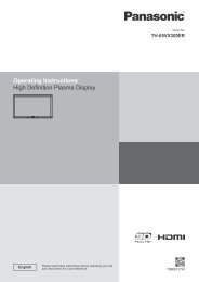
<strong>Operating</strong> <strong>Instructions</strong><br />
High De nition Plasma Display<br />
Englishh<br />
Please read these instructions before operating your set<br />
and retain them for future reference.<br />
Model No.<br />
<strong>TH</strong>-<strong>50PH30</strong>E
2<br />
Dear <strong>Panasonic</strong> Customer<br />
Welcome to the <strong>Panasonic</strong> family of customers. We hope that you will have many years of<br />
enjoyment from your new Plasma Display.<br />
To obtain maximum benefit from your set, please read these <strong>Instructions</strong> before making<br />
any adjustments, and retain them for future reference.<br />
Retain your purchase receipt also, and note down the model number and serial number of<br />
your set in the space provided on the rear cover of these instructions.<br />
Visit our <strong>Panasonic</strong> Web Site http://panasonic.net<br />
Table of Contents<br />
Important Safety Notice ........................................... 3<br />
Safety Precautions ................................................... 4<br />
Accessories .............................................................. 7<br />
Accessories Supply ................................................. 7<br />
Remote Control Batteries ........................................ 7<br />
Connections .............................................................. 8<br />
Speaker connection ................................................. 8<br />
AC cord connection and xing, cable xing ............. 8<br />
Video equipment connection ................................... 9<br />
VIDEO and COMPONENT / RGB IN connection .... 9<br />
HDMI connection ................................................... 10<br />
DVI-D IN connection .............................................. 10<br />
PC Input Terminals connection ...............................11<br />
SERIAL Terminals connection ............................... 12<br />
Power On / Off ......................................................... 13<br />
Selecting the input signal ...................................... 15<br />
Basic Controls ........................................................ 16<br />
ASPECT Controls ................................................... 18<br />
Digital Zoom ............................................................ 19<br />
On-Screen Menu Displays ..................................... 20<br />
Adjusting Pos./Size ................................................ 21<br />
Picture Adjustments ............................................... 23<br />
Advanced settings ................................................. 24<br />
Sound Adjustment .................................................. 25<br />
Screensaver (For preventing image retention) .... 26<br />
Setup of Screensaver Time ................................... 27<br />
Reduces screen image retention .......................... 28<br />
Extended life settings ............................................ 28<br />
Reduces power consumption ............................... 31<br />
Customizing the Input labels ................................. 32<br />
Selecting the On-Screen Menu Language ............ 33<br />
Display orientation ................................................. 33<br />
Setup for MULTI DISPLAY ...................................... 34<br />
How to Setup MULTI DISPLAY ............................. 34<br />
ID Remote Control Function .................................. 35<br />
Setup for Input Signals .......................................... 36<br />
Component / RGB-in select ................................... 36<br />
YUV / RGB-in select .............................................. 36<br />
Signal menu .......................................................... 37<br />
Colour system ....................................................... 38<br />
Cinema reality ....................................................... 38<br />
XGA Mode ............................................................. 38<br />
Noise reduction ..................................................... 39<br />
Sync ...................................................................... 40<br />
HDMI Range .......................................................... 40<br />
Input signal display ................................................ 40<br />
Options Adjustments ............................................. 41<br />
Audio input select .................................................. 44<br />
Touch Panel settings (Settings when using<br />
Touch Panel) ......................................................... 44<br />
Troubleshooting ..................................................... 45<br />
List of Aspect Modes ............................................. 46<br />
Applicable input signals ........................................ 47<br />
Shipping condition ................................................. 48<br />
Speci cations ......................................................... 49<br />
Trademark Credits<br />
• VGA is a trademark of International Business Machines Corporation.<br />
• Macintosh is a registered trademark of Apple Inc., USA.<br />
• SVGA, XGA, SXGA and UXGA are registered trademarks of the Video Electronics Standard Association.<br />
Even if no special notation has been made of company or product trademarks, these trademarks have been fully respected.<br />
• HDMI, the HDMI Logo, and High-De nition Multimedia Interface are trademarks or registered trademarks of HDMI<br />
Licensing LLC in the United States and other countries.<br />
Note:<br />
Do not allow a still picture to be displayed for an extended period, as this can cause a permanent image retention<br />
to remain on the Plasma Display.<br />
Examples of still pictures include logos, video games, computer images, teletext and images displayed in 4:3 mode.
Important Safety Notice<br />
WARNING<br />
1) To prevent damage which may result in re or shock hazard, do not expose this appliance to dripping<br />
or splashing.<br />
Do not place containers with water ( ower vase, cups, cosmetics, etc.) above the set. (including on<br />
shelves above, etc.)<br />
No naked ame sources, such as lighted candles, should be placed on / above the set.<br />
2) To prevent electric shock, do not remove cover. No user serviceable parts inside. Refer servicing to quali ed<br />
service personnel.<br />
3) Do not remove the earthing pin on the power plug. This apparatus is equipped with a three pin earthing-type<br />
power plug. This plug will only t an earthing-type power outlet. This is a safety feature. If you are unable to<br />
insert the plug into the outlet, contact an electrician.<br />
Do not defeat the purpose of the earthing plug.<br />
4) To prevent electric shock, ensure the earthing pin on the AC cord power plug is securely connected.<br />
CAUTION<br />
This appliance is intended for use in environments which are relatively free of electromagnetic elds.<br />
Using this appliance near sources of strong electromagnetic elds or where electrical noise may overlap with the<br />
input signals could cause the picture and sound to wobble or cause interference such as noise to appear.<br />
To avoid the possibility of harm to this appliance, keep it away from sources of strong electromagnetic elds.<br />
IMPORTANT: <strong>TH</strong>E MOULDED PLUG<br />
FOR YOUR SAFETY, PLEASE READ <strong>TH</strong>E FOLLOWING TEXT CAREFULLY.<br />
This display is supplied with a moulded three pin mains plug for your safety and convenience. A 10 amp fuse is<br />
tted in this plug. Shall the fuse need to be replaced, please ensure that the replacement fuse has a rating of 10<br />
amps and that it is approved by ASTA or BSI to BS1362.<br />
Check for the ASTA mark ASA or the BSI mark on the body of the fuse.<br />
If the plug contains a removable fuse cover, you must ensure that it is re tted when the fuse is replaced.<br />
If you lose the fuse cover the plug must not be used until a replacement cover is obtained.<br />
A replacement fuse cover can be purchased from your local <strong>Panasonic</strong> dealer.<br />
Do not cut off the mains plug.<br />
Do not use any other type of mains lead except the one supplied with this display.<br />
The supplied mains lead and moulded plug are designed to be used with this display to avoid<br />
interference and for your safety.<br />
If the socket outlet in your home is not suitable, get it changed by a quali ed electrician.<br />
If the plug or mains lead becomes damaged, purchase a replacement from an authorized dealer.<br />
WARNING : — <strong>TH</strong>IS DISPLAY MUST BE EAR<strong>TH</strong>ED.<br />
How to replace the fuse. Open the fuse compartment with a screwdriver and replace the fuse.<br />
3
4<br />
Safety Precautions<br />
WARNING<br />
Setup<br />
This Plasma Display is for use only with the following optional accessories. Use with any other type of optional<br />
accessories may cause instability which could result in the possibility of injury.<br />
(All of the following accessories are manufactured by <strong>Panasonic</strong> Corporation.)<br />
• Speakers ...................................................... TY-SP50P8W-K<br />
• Pedestal ....................................................... TY-ST20-K<br />
• Mobile stand ................................................. TY-ST58PF20<br />
• Wall-hanging bracket (vertical) ..................... TY-WK42PV20<br />
• Wall-hanging bracket (angled) ..................... TY-WK42PR20<br />
• Ceiling-hanging bracket ............................... TY-CE42PS20<br />
• Touch Panel ................................................. TY-TP50P10S<br />
Always be sure to ask a quali ed technician to carry out set-up.<br />
Small parts can present choking hazard if accidentally swallowed. Keep small parts away from young children. Discard<br />
unneeded small parts and other objects, including packaging materials and plastic bags/sheets to prevent them from<br />
being played with by young children, creating the potential risk of suffocation.<br />
Do not place the Plasma Display on sloped or unstable surfaces, and ensure that the Plasma Display does<br />
not hang over the edge of the base.<br />
• The Plasma Display may fall off or tip over.<br />
Do not place any objects on top of the Plasma Display.<br />
• If water is spills onto the Plasma Display or foreign objects get inside it, a short-circuit may occur which could result<br />
in re or electric shock. If any foreign objects get inside the Plasma Display, please consult your local <strong>Panasonic</strong><br />
dealer.<br />
Transport only in upright position!<br />
• Transporting the unit with its display panel facing upright or downward may cause damage to the internal<br />
circuitry.<br />
Ventilation should not be impeded by covering the ventilation openings with items such as newspapers, table<br />
cloths and curtains.<br />
For suf cient ventilation;<br />
If using the pedestal (optional accessory), leave a space of 10 cm or more at the top, left and right, and 7 cm<br />
or more at the rear, and also keep the space between the bottom of the display and the oor surface.<br />
If using some other setting-up method, follow the manual of it. (If there is no speci c indication of installation<br />
dimension in the installation manual, leave a space of 10 cm or more at the top, bottom, left and right, and 7 cm<br />
or more at the rear.)<br />
When installing the Plasma Display vertically;<br />
Turn up the power switch for the upward direction when you install the Plasma Display vertically.<br />
And set “Display orientation” to “Portrait” in Setup menu. (see page 33)
When using the Plasma Display<br />
The Plasma Display is designed to operate on 220 - 240 V AC, 50/60 Hz.<br />
Safety Precautions<br />
Do not cover the ventilation holes.<br />
• Doing so may cause the Plasma Display to overheat, which can cause re or damage to the Plasma Display.<br />
Do not stick any foreign objects into the Plasma Display.<br />
• Do not insert any metal or ammable objects into the ventilations holes or drop them onto the Plasma Display, as<br />
doing so can cause re or electric shock.<br />
Do not remove the cover or modify it in any way.<br />
• High voltages which can cause severe electric shocks are present inside the Plasma Display. For any inspection,<br />
adjustment and repair work, please contact your local <strong>Panasonic</strong> dealer.<br />
Ensure that the mains plug is easily accessible.<br />
An apparatus with CLASS I construction shall be connected to a mains socket outlet with a protective earthing connection.<br />
Do not use any power supply cord other than that provided with this unit.<br />
• Doing so may cause re or electric shocks.<br />
Securely insert the power supply plug as far as it will go.<br />
• If the plug is not fully inserted, heat may be generated which could cause re. If the plug is damaged or the wall<br />
socket is loose, they shall not be used.<br />
Do not handle the power supply plug with wet hands.<br />
• Doing so may cause electric shocks.<br />
Do not do anything that may damage the power cable. When disconnecting the power cable, pull on the plug body, not the cable.<br />
• Do not damage the cable, make any modi cations to it, place heavy objects on top of it, heat it, place it near any<br />
hot objects, twist it, bend it excessively or pull it. To do so may cause re and electric shock. If the power cable is<br />
damaged, have it repaired at your local <strong>Panasonic</strong> dealer.<br />
If the Plasma Display is not going to be used for any prolonged length of time, unplug the power supply plug<br />
from the wall outlet.<br />
To prevent the spread of re, keep candles or other open ames away from this product at all times.<br />
If problems occur during use<br />
If a problem occurs (such as no picture or no sound), or if smoke or an abnormal odour starts to come out<br />
from the Plasma Display, immediately unplug the power supply plug from the wall outlet.<br />
• If you continue to use the Plasma Display in this condition, re or electric shock could result. After checking that<br />
the smoke has stopped, contact your local <strong>Panasonic</strong> dealer so that the necessary repairs can be made. Repairing<br />
the Plasma Display yourself is extremely dangerous, and shall never be done.<br />
If water or foreign objects get inside the Plasma Display, if the Plasma Display is dropped, or if the cabinet<br />
becomes damages, disconnect the power supply plug immediately.<br />
• A short circuit may occur, which could cause re. Contact your local <strong>Panasonic</strong> dealer for any repairs that need to be made.<br />
5
6<br />
Safety Precautions<br />
CAUTION<br />
When using the Plasma Display<br />
Do not bring your hands, face or objects close to the ventilation holes of the Plasma Display.<br />
• Heated air comes out from the ventilation holes at the top of Plasma Display will be hot. Do not bring your hands<br />
or face, or objects which cannot withstand heat, close to this port, otherwise burns or deformation could result.<br />
Be sure to disconnect all cables before moving the Plasma Display.<br />
• If the Plasma Display is moved while some of the cables are still connected, the cables may become damaged,<br />
and re or electric shock could result.<br />
Disconnect the power supply plug from the wall socket as a safety precaution before carrying out any<br />
cleaning.<br />
• Electric shocks can result if this is not done.<br />
Clean the power cable regularly to prevent it becoming dusty.<br />
• If dust built up on the power cord plug, the resultant humidity can damage the insulation, which could result in re.<br />
Pull the power cord plug out from the wall outlet and wipe the mains lead with a dry cloth.<br />
Do not burn or breakup batteries.<br />
• Batteries must not be exposed to excessive heat such as sunshine, re or the like.<br />
This Plasma Display radiates infrared rays, therefore it may affect other infrared communication equipment.<br />
Install your infrared sensor in a place away from direct or re ected light from your Plasma Display.<br />
Cleaning and maintenance<br />
The front of the display panel has been specially treated. Wipe the panel surface gently using only a cleaning<br />
cloth or a soft, lint-free cloth.<br />
• If the surface is particularly dirty, wipe with a soft, lint-free cloth which has been soaked in pure water or water in<br />
which neutral detergent has been diluted 100 times, and then wipe it evenly with a dry cloth of the same type until<br />
the surface is dry.<br />
• Do not scratch or hit the surface of the panel with ngernails or other hard objects, otherwise the surface may<br />
become damaged. Furthermore, avoid contact with volatile substances such as insect sprays, solvents and thinner,<br />
otherwise the quality of the surface may be adversely affected.<br />
If the cabinet becomes dirty, wipe it with a soft, dry cloth.<br />
• If the cabinet is particularly dirty, soak the cloth in water to which a small amount of neutral detergent has been<br />
added and then wring the cloth dry. Use this cloth to wipe the cabinet, and then wipe it dry with a dry cloth.<br />
• Do not allow any detergent to come into direct contact with the surface of the Plasma Display. If water droplets get<br />
inside the unit, operating problems may result.<br />
• Avoid contact with volatile substances such as insect sprays, solvents and thinner, otherwise the quality of the<br />
cabinet surface may be adversely affected or the coating may peel off. Furthermore, do not leave it for long periods<br />
in contact with articles made from rubber or PVC.
Accessories<br />
Accessories Supply<br />
<strong>Operating</strong> Instruction book<br />
Power supply cord<br />
Check that you have the accessories and items shown<br />
Remote Control Batteries<br />
Requires two R6 batteries.<br />
1. Pull and hold the hook, then open<br />
the battery cover.<br />
Helpful Hint:<br />
CD-ROM<br />
(<strong>Operating</strong><br />
instructions)<br />
-<br />
+<br />
- +<br />
Remote Control<br />
Transmitter<br />
N2QAYB000535<br />
2. Insert batteries - note correct<br />
polarity ( + and -).<br />
“R6 (UM3)” size<br />
For frequent remote control users, replace old batteries with Alkaline<br />
batteries for longer life.<br />
3. Replace the cover.<br />
Batteries for the Remote<br />
Control Transmitter<br />
(R6 (UM3) Size × 2)<br />
Precaution on battery use<br />
Incorrect installation can cause battery leakage and corrosion that will damage the remote control transmitter.<br />
Disposal of batteries should be in an environment-friendly manner.<br />
Observe the following precaution:<br />
1. Batteries shall always be replaced as a pair. Always use new batteries when replacing the old set.<br />
2. Do not combine a used battery with a new one.<br />
3. Do not mix battery types (example: “Zinc Carbon” with “Alkaline”).<br />
4. Do not attempt to charge, short-circuit, disassemble, heat or burn used batteries.<br />
5. Battery replacement is necessary when remote control acts sporadically or stops operating the Plasma Display set.<br />
6. Do not burn or breakup batteries.<br />
Batteries must not be exposed to excessive heat such as sunshine, re or the like.<br />
7
Connections<br />
When connecting the speakers, be sure to use only the optional accessory speakers.<br />
Refer to the speaker’s Installation Manual for details on speaker installation.<br />
8<br />
Speaker connection<br />
Speaker<br />
terminal (R)<br />
Speakers (Optional accessories)<br />
AC cord connection (see page 13)<br />
AC cord xing<br />
Speaker<br />
terminal (L)<br />
AC cord connection and xing, cable xing<br />
Plug the AC cord into the display unit.<br />
Plug the AC cord until it clicks.<br />
Note:<br />
Make sure that the AC cord is locked on<br />
both the left and right sides.<br />
1<br />
2<br />
Unplug the AC cord<br />
Unplug the AC cord pressing the<br />
two knobs.<br />
Note:<br />
When disconnecting the AC cord, be<br />
absolutely sure to disconnect the AC<br />
cord plug at the socket outlet rst.<br />
Cable xing<br />
There are 3 holes to x the connection cables. As a clamper is not included with the<br />
product, provide a clamper or band as necessary.<br />
When using the Wall-hanging bracket (vertical)<br />
Note:<br />
When using the Wall-hanging bracket (vertical)(TY-WK42PV20), use the holes and to<br />
secure the cables. If the cables are xed on the hole , the cables may be caught by the<br />
wall-hanging bracket.<br />
Red<br />
Black<br />
While pressing the lever,<br />
insert the core wire.<br />
Black<br />
Return the lever.<br />
Red
Video equipment connection<br />
VIDEO and COMPONENT / RGB IN connection<br />
RCA-BNC<br />
adapter plug<br />
RCA-BNC<br />
adapter plug<br />
PC IN: PC Input Terminal<br />
Connect to video terminal<br />
of PC or equipment with<br />
Y, PB(CB) and PR(CR)<br />
output (see page 11).<br />
Note:<br />
Additional equipment, cables and adapter plugs shown are not supplied with this set.<br />
Y<br />
P B<br />
Y , P B , P R ,<br />
OUT<br />
PR<br />
L<br />
R<br />
L<br />
R<br />
AUDIO<br />
OUT<br />
AUDIO<br />
OUT<br />
VIDEO<br />
OUT<br />
VCR<br />
Connections<br />
SERIAL: Control the<br />
Plasma Display<br />
by connecting<br />
to PC (see<br />
page 12)<br />
Terminals are on the bottom side of the Plasma Display.<br />
AV IN (VIDEO): Composite Video Input Terminal (see below)<br />
COMPONENT/RGB IN: Component/RGB Video Input Terminal<br />
(see below)<br />
AV IN (HDMI): HDMI Input Terminal (see page 10)<br />
DVI-D IN: DVI-D Input Terminal (see page 10)<br />
Connect to video equipment such as VCR or DVD player.<br />
Notes:<br />
• Change the “Component/RGB -in select” setting in the “Setup”<br />
menu to “Component” (when Component signal connection) or<br />
“RGB” (when RGB signal connection). (see page 36)<br />
• Signals input to COMPONENT/RGB IN terminals correspond to<br />
Sync on G or Sync on Y.<br />
DVD Player<br />
Computer RGB Camcorder<br />
9
10<br />
Connections<br />
HDMI connection<br />
[Pin assignments and signal names]<br />
Pin No. Signal Name Pin No. Signal Name<br />
1 T.M.D.S Data2+ 11<br />
T.M.D.S Clock<br />
Shield<br />
2<br />
T.M.D.S Data2<br />
Shield<br />
12 T.M.D.S Clock-<br />
3 T.M.D.S Data2- 13 CEC<br />
4<br />
5<br />
T.M.D.S Data1+<br />
T.M.D.S Data1<br />
Shield<br />
14<br />
Reserved<br />
(N.C. on device)<br />
6 T.M.D.S Data1- 15 SCL<br />
7 T.M.D.S Data0+ 16 SDA<br />
8<br />
T.M.D.S Data0<br />
Shield<br />
17<br />
DDC/CEC<br />
Ground<br />
9 T.M.D.S Data0- 18 +5V Power<br />
10 T.M.D.S Clock+ 19 Hot Plug Detect<br />
DVI-D IN connection<br />
19 3 1<br />
Note:<br />
Additional equipment and HDMI cable shown are not supplied with this set.<br />
PC with DVI-D<br />
video out<br />
DVI-D Input Connector<br />
Pin Layouts<br />
9<br />
1<br />
17<br />
Connection port view<br />
8<br />
24<br />
16<br />
18<br />
Stereo mini plug (M3)<br />
4 2<br />
DVI-video cable (Within 5 m)<br />
HDMI<br />
AV OUT<br />
DVD player<br />
HDMI cable<br />
Pin No. Signal Name Pin No. Signal Name<br />
1 T.M.D.S. data 2- 13<br />
2 T.M.D.S. data 2+ 14 +5 V DC<br />
3 T.M.D.S. data 2 shield 15 Ground<br />
4 16 Hot plug detect<br />
5 17 T.M.D.S. data 0-<br />
6 DDC clock 18 T.M.D.S. data 0+<br />
7 DDC data 19 T.M.D.S. data 0 shield<br />
8 20<br />
9 T.M.D.S. data 1- 21<br />
10 T.M.D.S. data 1+ 22 T.M.D.S. clock shield<br />
11 T.M.D.S. data 1 shield 23 T.M.D.S. clock+<br />
12 24 T.M.D.S. clock-<br />
Notes:<br />
• Additional equipment and cables shown are not supplied with this set.<br />
• Use the DVI-D cable complying with the DVI standard. Image deterioration may occur depending on the length or<br />
the quality of the cable.
PC Input Terminals connection<br />
COMPUTER<br />
Conversion adapter<br />
(if necessary)<br />
Audio<br />
Stereo mini plug (M3)<br />
Connect a cable which matches<br />
the audio output terminal on the computer.<br />
RGB<br />
PC cable<br />
Mini D-sub 15p<br />
Notes:<br />
• With regard to the typical PC input signals that are described in the applicable input signals list (see page 47), adjustment<br />
values such as for the standard picture positions and sizes have already been stored in this unit. You can add up to eight<br />
PC input signal types that are not included in the list.<br />
• Computer signals which can be input are those with a horizontal scanning frequency of 15 to 110 kHz and vertical scanning<br />
frequency of 48 to 120 Hz. (However, the image will not be displayed properly if the signals exceed 1,200 lines.)<br />
• The display resolution is a maximum of 768 × 768 dots when the aspect mode is set to “4:3”, and 1,024 × 768 dots<br />
when the aspect mode is set to “16:9”. If the display resolution exceeds these maximums, it may not be possible to<br />
show ne detail with suf cient clarity.<br />
• The PC input terminals are DDC2B-compatible. If the computer being connected is not DDC2B-compatible, you will<br />
need to make setting changes to the computer at the time of connection.<br />
• Some PC models cannot be connected to the set.<br />
• There is no need to use an adapter for computers with DOS/V compatible Mini D-sub 15P terminal.<br />
• The computer shown in the illustration is for example purposes only.<br />
• Additional equipment and cables shown are not supplied with this set.<br />
• Do not set the horizontal and vertical scanning frequencies for PC signals which are above or below the speci ed<br />
frequency range.<br />
• Component Input is possible with the pin 1, 2, 3 of the Mini D-sub 15P Connector.<br />
• Change the “Component/RGB-in select” setting in the “Setup” menu to “Component”<br />
(when Component signal connection) or “RGB” (when RGB signal connection). (see page 36)<br />
Signal Names for Mini D-sub 15P Connector<br />
Pin No. Signal Name Pin No. Signal Name Pin No. Signal Name<br />
11 12 13 14 15<br />
6 7 8 9 10<br />
1 2 3 4 5<br />
1<br />
2<br />
R (PR/CR)<br />
G (Y)<br />
6<br />
7<br />
GND (Ground)<br />
GND (Ground)<br />
11<br />
12<br />
NC (not connected)<br />
SDA<br />
3 B (PB/CB) 8 GND (Ground) 13 HD/SYNC<br />
Pin Layout for PC Input 4 NC (not connected) 9 +5 V DC 14 VD<br />
Terminal<br />
5 GND (Ground) 10 GND (Ground) 15 SCL<br />
(Male)<br />
(Female)<br />
Connections<br />
11
12<br />
Connections<br />
SERIAL Terminals connection<br />
The SERIAL terminal is used when the Plasma Display is controlled by a computer.<br />
(Male)<br />
COMPUTER<br />
D-sub 9p<br />
Notes:<br />
• Use the RS-232C straight cable to connect the computer to the Plasma Display.<br />
• The computer shown is for example purposes only.<br />
• Additional equipment and cables shown are not supplied with this set.<br />
The SERIAL terminal conforms to the RS-232C interface<br />
speci cation, so that the Plasma Display can be controlled<br />
by a computer which is connected to this terminal.<br />
The computer will require software which allows the<br />
sending and receiving of control data which satisfies<br />
the conditions given below. Use a computer application<br />
such as programming language software. Refer to the<br />
documentation for the computer application for details.<br />
Communication parameters<br />
Basic format for control data<br />
The transmission of control data from the computer<br />
starts with a STX signal, followed by the command, the<br />
parameters, and lastly an ETX signal in that order. If there<br />
are no parameters, then the parameter signal does not<br />
need to be sent.<br />
STX C1 C2 C3 : P1 P2 P3 P4 P5 ETX<br />
Start<br />
(02h)<br />
Colon Parameter(s)<br />
3-character<br />
command (3 bytes)<br />
(1 - 5 bytes)<br />
RS-232C Straight cable<br />
Signal level RS-232C compliant<br />
Synchronization method Asynchronous<br />
Baud rate 9600 bps<br />
Parity None<br />
Character length 8 bits<br />
Stop bit 1 bit<br />
Flow control -<br />
End<br />
(03h)<br />
Notes:<br />
• If multiple commands are transmitted, be sure to wait for<br />
the response for the rst command to come from this unit<br />
before sending the next command.<br />
• If an incorrect command is sent by mistake, this unit will<br />
send an “ER401” command back to the computer.<br />
(Female)<br />
9<br />
8<br />
7<br />
5 4 3 2<br />
6<br />
Pin layout for SERIAL Terminal<br />
Signal names for D-sub 9P connector<br />
Pin No. Details<br />
2 R X D<br />
3 T X D<br />
5 GND<br />
4 • 6 Non use<br />
7<br />
(Shorted in this set)<br />
8<br />
1 • 9 NC<br />
These signal names are those of computer speci cations.<br />
Command<br />
Command Parameter Control details<br />
PON None Power ON<br />
POF None Power OFF<br />
AVL ** Volume 00 - 63<br />
AMT<br />
0<br />
1<br />
Audio MUTE OFF<br />
Audio MUTE ON<br />
IMS None<br />
VD1<br />
YP1<br />
HM1<br />
DV1<br />
PC1<br />
DAM None<br />
ZOOM<br />
FULL<br />
JUST<br />
NORM<br />
ZOM2<br />
ZOM3<br />
SJST<br />
SNOM<br />
SFUL<br />
14:9<br />
Input select (toggle)<br />
VIDEO input (VIDEO)<br />
COMPONENT/RGB IN input<br />
(COMPONENT)<br />
HDMI input (HDMI)<br />
DVI-D IN input (DVI)<br />
PC IN input (PC)<br />
Screen mode select (toggle)<br />
Zoom1 (For Video/SD/PC signal)<br />
16:9<br />
Just (For Video/SD signal)<br />
4:3 (For Video/SD/PC signal)<br />
Zoom2 (For HD signal)<br />
Zoom3 (For HD signal)<br />
Just (For HD signal)<br />
4:3 (For HD signal)<br />
4:3 Full (For HD signal)<br />
14:9<br />
With the power off, this display responds to PON command<br />
only.<br />
1
Power On / Off<br />
Connecting the AC cord plug to the Plasma Display.<br />
Connecting the plug to the Wall Outlet<br />
Notes:<br />
• Main plug types vary between countries. The power<br />
plug shown at right may, therefore, not be the type<br />
tted to your set.<br />
• When disconnecting the AC cord, be absolutely<br />
sure to disconnect the AC cord plug at the socket<br />
outlet rst.<br />
Press the Power switch on the Plasma Display to<br />
turn the set on: Power-On.<br />
Power Indicator: Green<br />
INPUT MENU -/ VOL +/ ENTER/<br />
Press the button on the remote control to turn the Plasma Display off.<br />
Power Indicator: Red (standby)<br />
Press the button on the remote control to turn the Plasma Display on.<br />
Power Indicator: Green<br />
Turn the power to the Plasma Display off by pressing the switch on the<br />
unit, when the Plasma Display is on or in standby mode.<br />
Note:<br />
During operation of the power management function, the power indicator turns<br />
orange in the power off state.<br />
Power Indicator<br />
Remote Control Sensor<br />
13
14<br />
Power On / Off<br />
When rst switching on the unit<br />
Following screen will be displayed when the unit is turned on for the rst time.<br />
Select the items with the remote control. Unit buttons are invalid.<br />
OSD Language<br />
No activity power off<br />
Display orientation<br />
1 Select the language.<br />
2 Set.<br />
1 To enable No activity power off, select “Enable”.<br />
2 Set.<br />
1 “Select “Yes” or “No”.<br />
2 Set.<br />
No activity power off Precautions<br />
1 For vertical installation, select “Portrait”.<br />
2 Set.<br />
If “No activity power off” in Setup menu is set to<br />
“Enable”, a warning message is displayed every<br />
time the power is turned ON. (See page 31)<br />
If you do not need this display, the settings of<br />
“Power On Message” in Options menu can<br />
relieve you of it. (See page 43)<br />
OSD Language<br />
English (UK)<br />
Deutsch<br />
Français<br />
Italiano<br />
Español<br />
ENGLISH (US)<br />
Select<br />
No activity power off<br />
Set<br />
Display will be turned off<br />
when there is no activity for 4 hours.<br />
Enable<br />
No activity power off<br />
Disable<br />
If selecting “Enable”, a<br />
con rmation window appears.<br />
Are you sure<br />
you want to enable ’No activity power off’ ?<br />
Yes No<br />
Display orientation<br />
Landscape<br />
Portrait<br />
Notes:<br />
• Once the items are set, the screens won't be displayed when switching on the unit next time.<br />
• After the setting, the items can be changed in the following menus.<br />
OSD Language (see page 33)<br />
No activity power off (see page 31)<br />
Display orientation (see page 33)<br />
’No activity power off’ is enabled.
Selecting the input signal<br />
Press to select the input signal to be played back from the equipment which has<br />
been connected to the Plasma Display.<br />
Input signals will change as follows:<br />
PC VIDEO COMPONENT* HDMI DVI<br />
PC: PC input terminal in PC IN.<br />
VIDEO: Video input terminal in AV IN (VIDEO).<br />
COMPONENT*: Component or RGB input terminal in COMPONENT/RGB IN.<br />
HDMI: HDMI input terminal in AV IN (HDMI).<br />
DVI: DVI input terminal in DVI-D IN.<br />
* “COMPONENT” may be displayed as “RGB” depending on the setting of<br />
“Component/RGB-in select”. (see page 36)<br />
Notes:<br />
• Selecting is also possible by pressing the INPUT button on the unit.<br />
• Outputs the sound as set in “Audio input select” in the Options menu. (see page 44)<br />
• Select to match the signals from the source connected to the component/RGB input<br />
terminals. (see page 36)<br />
• Image retention (image lag) may occur on the plasma display panel when a still picture<br />
is kept on the panel for an extended period. The function that darkens the screen<br />
slightly is activated to prevent image retention (see page 45), but this function is not<br />
the perfect solution to image retention.<br />
INPUT MENU -/ VOL +/ ENTER/<br />
INPUT MENU - / VOL + / ENTER/<br />
15
16<br />
Basic Controls<br />
Main Unit<br />
Remote control sensor<br />
Main Power On / Off Switch<br />
Power Indicator<br />
The Power Indicator will light.<br />
• Power-OFF .... Indicator not illuminated (The unit<br />
will still consume some power<br />
as long as the power cord is still<br />
inserted into the wall outlet.)<br />
• Standby ........ Red<br />
• Power-ON ...... Green<br />
• PC Power management (DPMS)<br />
.........................Orange (With PC input signal.<br />
See page 31)<br />
• DVI-D Power management<br />
.........................Orange (With DVI input signal.<br />
See page 31)<br />
INPUT MENU -/ VOL +/ ENTER/<br />
MENU Screen ON / OFF<br />
Each time the MENU button is pressed, the menu<br />
screen will switch. (see page 20)<br />
Normal Viewing Picture<br />
Sound Pos./Size Setup<br />
INPUT button<br />
(INPUT signal selection)<br />
(see page 15)<br />
Volume Adjustment<br />
Volume Up “+” Down “–”<br />
When the menu screen is<br />
displayed:<br />
“+” : press to move the cursor up<br />
“–” : press to move the cursor down<br />
(see page 20)<br />
Enter / Aspect button<br />
(see page 18, 20)
Remote Control Transmitter<br />
ACTION button<br />
Press to make selections.<br />
ASPECT button<br />
Press to adjust the aspect.<br />
(see page 18)<br />
Standby (ON / OFF) button<br />
The Plasma Display must first be<br />
plugged into the wall outlet and turned<br />
on at the power switch (see page 13).<br />
Press this button to turn the Plasma<br />
Display On, from Standby mode. Press<br />
it again to turn the Plasma Display Off<br />
to Standby mode.<br />
POS./SIZE button<br />
(see page 21)<br />
PICTURE button<br />
(see page 23)<br />
Sound mute On / Off<br />
Press this button to mute the<br />
sound.<br />
Press again to reactivate sound.<br />
Sound is also reactivated when<br />
power is turned off or volume level<br />
is changed.<br />
N button<br />
(see page 22, 23, 24, 25)<br />
POSITION buttons<br />
INPUT button<br />
Press to select Input signal<br />
sequentially. (see page 15)<br />
Basic Controls<br />
OFF TIMER button<br />
The Plasma Display can be preset to switch to<br />
stand-by after a xed period. The setting changes<br />
to 30 minutes, 60 minutes, 90 minutes and 0<br />
minutes (off timer cancelled) each time the button<br />
is pressed.<br />
30 min 60 min<br />
0 min (Cancel)<br />
90 min<br />
When three minutes remain, “Off timer 3 min”<br />
will ash.<br />
The off timer is cancelled if a power interruption<br />
occurs.<br />
AUTO SETUP button<br />
Automatically adjusts the position/<br />
size of the screen. (see page 21)<br />
SET UP button (see page 20)<br />
SOUND button (see page 25)<br />
Volume Adjustment<br />
Press the Volume Up “+” or Down “–”<br />
button to increase or decrease the<br />
sound volume level.<br />
R button (see page 20)<br />
Press the R button to return to<br />
previous menu screen.<br />
RECALL button<br />
Press the “RECALL” button to display<br />
the current system status.<br />
1 Input label<br />
2 Aspect mode (see page 18)<br />
Audio input (see page 44)<br />
NANODRIFT Saver operating<br />
(see page 29)<br />
3 Off timer<br />
The off timer indicator is<br />
displayed only when the off<br />
timer has been set.<br />
PC<br />
4:3<br />
COMPONENT<br />
NANODRIFT<br />
Off timer 90min<br />
Digital Zoom (see page 19)<br />
1<br />
2<br />
3<br />
17
INPUT MENU -/ VOL +/ ENTER/<br />
18<br />
ASPECT Controls<br />
The Plasma Display will allow you to enjoy viewing the picture at its maximum size, including wide screen cinema<br />
format picture.<br />
Note:<br />
Be aware that if you put the display in a public place for commercial purposes or a public showing and then use the<br />
aspect mode select function to shrink or expand the picture, you may be violating the copyright under copyright law.<br />
It is prohibited to show or alter the copyrighted materials of other people for commercial purposes without the prior<br />
permission of the copyright holder.<br />
[from the unit]<br />
For PC signal input:<br />
4:3 Zoom 16:9<br />
Press repeatedly to move through the aspect options:<br />
For details about the aspect mode, please see “List of Aspect Modes” (page 46).<br />
For VIDEO signal input:<br />
4:3 Zoom1 Zoom2 Zoom3 16:9 14:9 Just<br />
The aspect mode changes each time the ENTER button is pressed.<br />
For SD signal input (525 (480) / 60i • 60p, 625 (575) / 50i • 50p):<br />
4:3 Zoom1 Zoom2 Zoom3 16:9 14:9 Just<br />
For HD signal input [1125 (1080) / 60i • 50i • 60p • 50p • 24p • 25p • 30p • 24sF, 750 (720) / 60p • 50p]:<br />
4:3 4:3 Full Zoom1 Zoom2 Notes:<br />
Just 14:9 16:9 Zoom3 • The aspect mode is memorized separately for each input<br />
terminal.<br />
• Do not allow the picture to be displayed in 4:3 mode for an<br />
extended period, as this can cause a permanent image retention<br />
All Aspect mode<br />
to remain on the Plasma Display Panel.<br />
Set “All Aspect” to “On” in Options menu to enable the extended aspect mode (page 43). When All Aspect mode, the aspect<br />
mode of pictures is switched as follows. For details about the aspect mode, please see “List of Aspect Modes” (page 46)<br />
For VIDEO signal input:<br />
4:3 Zoom1 Zoom2 Zoom3 16:9 14:9 Just<br />
For PC signal input:<br />
4:3 Zoom 16:9<br />
For SD signal input (525 (480) / 60i • 60p, 625 (575) / 50i • 50p):<br />
4:3 Zoom1 Zoom2 Zoom3 16:9 14:9 Just<br />
For HD signal input [1125 (1080) / 60i • 50i • 60p • 50p • 24p • 25p • 30p • 24sF, 750 (720) / 60p • 50p]:<br />
4:3 Full Zoom1 Zoom2 Zoom3 16:9 14:9 Just1 Just2 4:3 (1) 4:3 (2)
Digital Zoom<br />
This displays an enlargement of the designated part of the displayed image.<br />
Display the operation guide.<br />
1<br />
2<br />
3<br />
4<br />
Press to access Digital Zoom.<br />
The operation guide will be displayed.<br />
During Digital Zoom, only the following buttons can be operated.<br />
[Remote control]<br />
Select the area of the image to be enlarged.<br />
Press on the enlargement location to select.<br />
Select the magni cation required for the enlarged display.<br />
Each time this is pressed, the magni cation factor changes.<br />
This is shown in the image being displayed.<br />
Return to normal display (quit Digital Zoom).<br />
OFF TIMER button<br />
VOL button<br />
MUTE button<br />
POSITION /<br />
ACTION button<br />
The cursor will move.<br />
Press to exit from the Digital Zoom.<br />
[Unit]<br />
Notes:<br />
• When power goes OFF (including “Off Timer” operation), Digital Zoom terminates.<br />
• The Digital Zoom function cannot be selected while in the following operation state:<br />
When MULTI DISPLAY Setup is On (see page 34).<br />
When Screensaver (except for Negative image) is running (see page 26)<br />
• While Digital Zoom is in operation, “Adjusting Pos./ Size” cannot be used.<br />
INPUT MENU -/ VOL +/ ENTER/<br />
VOL button<br />
× 1 × 2 × 3 × 4<br />
Exit<br />
Exit<br />
1<br />
2<br />
19
1<br />
2<br />
20<br />
On-Screen Menu Displays<br />
Display the menu screen.<br />
Select the item.<br />
Picture<br />
Normalise Normal<br />
Picture Mode<br />
Normal<br />
Contrast<br />
25<br />
Brightness<br />
0<br />
Colour<br />
0<br />
Hue<br />
0<br />
Sharpness<br />
5<br />
White balance Normal<br />
Colour Management<br />
Advanced settings<br />
Off<br />
(Example: Picture menu)<br />
Remote Control Unit<br />
Press to select.<br />
(Example: Picture menu)<br />
MENU<br />
Press several times.<br />
Each time the MENU button is pressed, the<br />
menu screen will switch.<br />
Normal Viewing Picture<br />
Sound Pos./Size Setup<br />
Select. Select.<br />
3 Set. Set. Set.<br />
4<br />
Exit the menu.<br />
MENU<br />
Press.<br />
Press to return to the previous menu.<br />
Press.<br />
Press.<br />
Press several times.<br />
Menu display list<br />
Note: Menu that cannot be adjusted is grayout. Adjustable menu changes depending on signal, input and menu setting.<br />
Picture menu Setup menu Pos./Size menu Sound menu<br />
Picture<br />
Normalise Normal<br />
Picture Mode<br />
Normal<br />
Contrast<br />
25<br />
Brightness<br />
0<br />
Colour<br />
0<br />
Hue<br />
0<br />
Sharpness<br />
5<br />
White balance Normal<br />
Colour Management<br />
Advanced settings<br />
Off<br />
see page 23, 24<br />
Setup<br />
1/2<br />
Signal<br />
Screensaver<br />
Extended life settings<br />
Input label<br />
Component/RGB-in select<br />
RGB<br />
Power save<br />
Off<br />
PC Power management Off<br />
DVI-D Power management Off<br />
No signal power off<br />
Disable<br />
No activity power off Enable<br />
OSD Language English (UK)<br />
Setup<br />
MULTI DISPLAY Setup<br />
Display orientation Landscape<br />
see page 26-40<br />
2/2<br />
Pos./Size<br />
Normalise<br />
Auto Setup<br />
Normal<br />
H-Pos<br />
0<br />
H-Size<br />
0<br />
V-Pos<br />
0<br />
V-Size<br />
0<br />
Dot Clock<br />
0<br />
Clock Phase<br />
0<br />
Clamp Position<br />
0<br />
Over scan Off<br />
see page 21, 22<br />
Sound<br />
Normalise Normal<br />
Sound Mode<br />
Bass<br />
Treble<br />
Balance<br />
see page 25<br />
0<br />
0<br />
0<br />
Normal
Adjusting Pos./Size<br />
1 Press to display the Pos./Size menu.<br />
2<br />
3<br />
4<br />
Press to select the menu to adjust.<br />
Press to adjust the menu.<br />
Press to exit from adjust mode.<br />
Pos./Size<br />
Normalise<br />
Auto Setup<br />
Normal<br />
H-Pos<br />
0<br />
H-Size<br />
0<br />
V-Pos<br />
0<br />
V-Size<br />
0<br />
Dot Clock<br />
0<br />
Clock Phase<br />
0<br />
Clamp Position<br />
0<br />
Over scan Off<br />
Notes:<br />
Unadjustable items are grayed<br />
out.<br />
Adjustable items differ depending<br />
on the input signal and the display<br />
mode.<br />
Notes:<br />
• Adjustment details are memorized separately for different input signal formats (Adjustments for component signals<br />
are memorized for 525 (480) / 60i · 60p, 625 (575) / 50i · 50p, 1125 (1080) / 60i · 50i · 60p · 50p · 24p · 25p · 30p ·<br />
24sF, 750 (720) / 60p · 50p each, and RGB/PC/Digital signals are memorized for each frequency.)<br />
• If a “Cue” or “Rew” signal from a VCR or DVD player is received, the picture position will shift up or down. This picture<br />
position movement cannot be controlled by the Picture Pos./Size function.<br />
Auto Setup When inputting a PC signal as an example, “H-Pos/V-Pos”, “H-Size/V-Size”, “Dot Clock” and “Clock<br />
Phase” are automatically corrected.<br />
This setting is enabled under the following conditions:<br />
• This setting is not activated during Multiple display or Digital Zoom.<br />
• When inputting an analog signal (Component/PC):<br />
This setting is enabled if “Component/RGB-in Select” (see page 36) in Setup menu is “RGB”.<br />
• When inputting a digital signal (HDMI/DVI):<br />
A PC format signal enables this setting.<br />
If other than a PC format signal, this setting is enabled with “Over scan” (see page 22) set to “Off”,<br />
and H-Size/V-Size cannot make automatic corrections.<br />
This setting will be invalid and will not work under the following conditions:<br />
• When VIDEO signal input<br />
• Aspect is set to “Just”<br />
• “Display size” in the Options menu (see page 42) is set to “On”<br />
Using Remote Control<br />
When on the remote control is pressed, “Auto Setup” will be executed.<br />
When Auto Setup does not work, “Invalid” is displayed.<br />
Auto mode<br />
When the “Auto Setup“ is set to “Auto” in the Options menu (see page 43), automatic position adjustment starts:<br />
• When the display power is turned ON.<br />
• When the input signal is switched.<br />
21
22<br />
Adjusting Pos./Size<br />
H-Pos Adjust the horizontal position. V-Pos Adjust the vertical position.<br />
H-Size Adjust the horizontal size. V-Size Adjust the vertical size.<br />
Dot Clock (During Component/PC input signal)<br />
Periodic striped pattern interference (noise) may occur when a striped pattern is displayed. If this happens,<br />
adjust so that any such noise is minimized.<br />
Clock<br />
Phase<br />
Clamp<br />
Position<br />
Notes:<br />
• If the dot clock frequency of an analog signal is 108 MHz or higher, “Dot Clock” and “Clock Phase”<br />
cannot be automatically corrected.<br />
• When digital signal input, Dot Clock and Clock Phase cannot be made.<br />
• Auto Setup may not work when a cropped or dark image is input. In such case, switch to a bright<br />
image with borders and other objects are clearly shown, and then try auto setup again.<br />
• Depending on the signal, out of alignment may occur after Auto Setup. Carry out ne tuning for the<br />
position/size as required.<br />
• If Auto Setup cannot set properly for vertical frequency 60Hz XGA signal (1024×768@60Hz,<br />
1280×768@60Hz, and 1366×768@60Hz), pre-selecting the individual signal in “XGA Mode” (see<br />
page 38) may results in correct Auto Setup.<br />
• Auto Setup does not work well when a signal such as additional information is superimposed out<br />
of valid image period or intervals between synchronizing and image signals are short, or for image<br />
signal with tri-level synchronizing signal added.<br />
• If Auto Setup cannot adjust correctly, select “Normalise” once and press ACTION ( ), then adjust<br />
Pos./Size manually.<br />
(During Component/PC input signal)<br />
Eliminate the ickering and distortion.<br />
(During Component/PC input signal)<br />
Adjusts the clamp position when black parts of the image have no detail due to underexposure or are<br />
tinged with green.<br />
Optimum value for Clamp Position adjustment<br />
When black parts have no detail due to underexposure (blackout)<br />
Value that causes least blackout is the optimum.<br />
When black parts are tinged with green<br />
Value that cancels the greenishness without causing blackout is the optimum.<br />
Over scan Turn image over scan On/Off.<br />
Con gurable signals are as follows:<br />
525i, 525p, 625i, 625p, 750/60p, 750/50p, 1125/60i, 1125/50i, 1125/24sF, 1125/25p, 1125/24p, 1125/60p,<br />
1125/50p, 1125/30p (Component Video, RGB, DVI, HDMI)<br />
On Off<br />
Notes:<br />
• When “Off” is set, “H-Size” and “V-Size” cannot be adjusted.<br />
• When the “Display size” is set to “On” in the Options menu, this setting will be invalid. (see page 42)<br />
Helpful Hint ( / Normalise Normalisation)<br />
While the Pos./ Size display is active, if either the N button on the remote control is pressed at any time or the ACTION<br />
( ) button is pressed during “Normalise”, then all adjustment values are returned to the factory settings.
1<br />
2<br />
Picture Adjustments<br />
Select to adjust each item.<br />
Picture<br />
Normalise Normal<br />
Picture Mode<br />
Normal<br />
Contrast<br />
25<br />
Brightness<br />
0<br />
Colour<br />
0<br />
Hue<br />
0<br />
Sharpness<br />
5<br />
White balance Normal<br />
Colour Management<br />
Advanced settings<br />
Off<br />
Advanced settings<br />
Normalise Normal<br />
Black extension<br />
Input level<br />
Gamma<br />
W/B High R<br />
W/B High G<br />
W/B High B<br />
W/B Low R<br />
W/B Low G<br />
W/B Low B<br />
Press to display the Picture menu.<br />
Press to select the menu to adjust.<br />
Select the desired level by looking at the picture behind the menu.<br />
Note:<br />
Menu that cannot be adjusted is grayout. Adjustable menu changes depending on signal, input<br />
and menu setting.<br />
Press to enter<br />
Advanced settings .<br />
Advanced settings<br />
Enables ne picture adjustment at a professional<br />
level (see next page).<br />
0<br />
0<br />
0<br />
0<br />
0<br />
0<br />
0<br />
0<br />
2.2<br />
Helpful Hint ( / Normalise Normalisation)<br />
Press “ ” or “ ” button to switch between modes.<br />
Normal<br />
Dynamic<br />
Cinema<br />
Normal<br />
For viewing in standard (evening lighting)<br />
environments.<br />
This menu selects the normal levels of Brightness<br />
and Contrast.<br />
Dynamic<br />
For viewing in brighter environments.<br />
This menu selects higher than normal levels of<br />
Brightness and Contrast.<br />
Cinema<br />
Ideal for movies.<br />
Note:<br />
If you would like to change the picture and colour<br />
of the selected Picture menu to something else,<br />
adjust using the items in the Picture menu. (see<br />
next page)<br />
Press “ ” or “ ” button to switch between modes.<br />
Normal Cool Warm<br />
Colour Management On<br />
Enables vivid colour adjustment automatically.<br />
While the “Picture” menu is displayed, if either the N button on the remote control is pressed at any time or the<br />
ACTION ( ) button is pressed during “Normalise”, then all adjustment values are returned to the factory settings.<br />
23
24<br />
Picture Adjustments<br />
Item Effect Adjustments<br />
Contrast<br />
Less More<br />
Selects the proper brightness<br />
and density for the room.<br />
Adjusts for easier viewing of<br />
Brightness<br />
Darker Brighter<br />
dark pictures such as night<br />
scenes and black hair.<br />
Colour<br />
Hue<br />
Sharpness<br />
Less More<br />
Reddish Greenish<br />
Less More<br />
Advanced settings<br />
Adjusts colour saturation.<br />
Adjusts for nice skin colour.<br />
Adjusts picture sharpness.<br />
Item Effect Details<br />
Black<br />
extension Less More<br />
Adjusts the dark shades of the image in gradation.<br />
Input level<br />
Less More<br />
Gamma<br />
W/B High<br />
Down Up<br />
R<br />
W/B High<br />
Less More<br />
G<br />
W/B High<br />
Less More<br />
B Less More<br />
W/B Low R<br />
W/B Low G<br />
W/B Low B<br />
Less More<br />
Less More<br />
Less More<br />
Helpful Hint ( / Normalise Normalisation)<br />
Notes:<br />
• You can change the level of each function<br />
(Contrast, Brightness, Colour, Hue,<br />
Sharpness) for each Picture Mode.<br />
• The setting details for Normal, Dynamic<br />
and Cinema respectively are memorized<br />
separately for each input terminal.<br />
• In Contrast, there is not a noticeable change<br />
even when contrast is increased with a bright<br />
picture or reduced with a dark picture.<br />
Adjustment of parts which are extremely bright and hard to see.<br />
S Curve 2.0 2.2 2.6<br />
Adjusts the white balance for light red areas.<br />
Adjusts the white balance for light green areas.<br />
Adjusts the white balance for light blue areas.<br />
Adjusts the white balance for dark red areas.<br />
Adjusts the white balance for dark green areas.<br />
Adjusts the white balance for dark blue areas.<br />
Notes:<br />
• Carry out “W/B” adjustment as follows.<br />
1. Adjust the white balance of the bright sections using the “W/B High R”, “W/B High G” and “W/B High B” settings.<br />
2. Adjust the white balance of the dark sections using the “W/B Low R”, “W/B Low G” and “W/B Low B” settings.<br />
3. Repeat steps 1 and 2 to adjust.<br />
Steps 1 and 2 affect each other’s settings, so repeat each step in turn to make the adjustment.<br />
• The adjustment values are memorized separately for each input terminal.<br />
• The adjustment range values should be used as an adjustment reference.<br />
On the remote control unit, while the “Advanced settings” menu is displayed, if either the N button is pressed at any time or<br />
the ACTION ( ) button is pressed during “Normalise”, then all adjustment values are returned to the factory settings.
Sound Adjustment<br />
1 Press to display the Sound menu.<br />
2<br />
Select to adjust each item.<br />
Press to select the menu to adjust.<br />
Select the desired level by listening to the sound.<br />
3 Press to exit from adjust mode.<br />
Item Details<br />
Sound Mode<br />
Normal: Emits the original sound.<br />
Dynamic: Accentuates sharp sound.<br />
Bass Adjusts low pitch sounds.<br />
Treble Adjusts high pitch sounds.<br />
Balance Adjusts left and right volumes.<br />
Note: Bass and Treble settings are memorized separately for each Sound Mode.<br />
Helpful Hint ( / Normalise Normalisation)<br />
Sound<br />
Normalise Normal<br />
Sound Mode<br />
Bass<br />
Treble<br />
Balance<br />
While the “Sound” menu is displayed, if either the N button on the remote control is pressed at any time or the<br />
ACTION ( ) button is pressed during “Normalise”, then all adjustment values are returned to the factory settings.<br />
0<br />
0<br />
0<br />
Normal<br />
25
26<br />
Screensaver (For preventing image retention)<br />
Do not display a still picture, especially in 4:3 mode, for any length of time.<br />
If the display must remain on, a Screensaver should be used.<br />
1<br />
2<br />
3<br />
4<br />
5<br />
Function selection<br />
Mode selection<br />
Start setting<br />
Press to display the Setup menu.<br />
Press to select Screensaver.<br />
Press to display Screensaver screen.<br />
Press to select Function.<br />
Press to select the desired function.<br />
Negative image<br />
White screen<br />
Press to select Mode.<br />
Press to select each<br />
mode items.<br />
Scrolling bar only<br />
Overlay scrolling bar<br />
Off<br />
When the Mode is set to On, press to select Start.<br />
Setup<br />
Screensaver<br />
Start<br />
Function Scrolling bar only<br />
Mode Off<br />
1/2<br />
Signal<br />
Screensaver<br />
Extended life settings<br />
Input label<br />
Component/RGB-in select<br />
RGB<br />
Power save<br />
Off<br />
PC Power management Off<br />
DVI-D Power management Off<br />
No signal power off<br />
Disable<br />
No activity power off Enable<br />
OSD Language English (UK)<br />
Negative image : Negative image will be displayed on the screen.<br />
Scrolling bar only : A white bar will scroll from left to right. The image won't be displayed.<br />
Overlay scrolling bar : The brightness of the image will be decreased and a white bar will scroll on it.<br />
White screen : The whole screen will be white.<br />
Interval : Operates when Periodic Time and <strong>Operating</strong><br />
Time are setup and those times arrive.<br />
Standby after SCR Saver:<br />
Operates while Screensaver duration, and<br />
display enters standby mode.<br />
On : Operates when Start is selected and the<br />
ACTION ( ) button is pressed.<br />
Press to start Screensaver.<br />
The menu screen will disappear and the Screensaver will be activated. To stop the<br />
Screensaver under On, press the R button or any buttons on the main unit.<br />
Note: When the display is turned off, the Scrensaver will be deactivated.
Setup of Screensaver Time<br />
After selecting Interval or Standby after SCR Saver, the relevant Time Setup will become available for selection and<br />
the <strong>Operating</strong> Time may be set. (Time cannot be set when “Mode” is “On” or “Off”.)<br />
Press to select Periodic Time / <strong>Operating</strong> Time<br />
(When Interval is selected).<br />
Press to select Screensaver duration<br />
(When Standby after SCR Saver is selected).<br />
Press to setup.<br />
button: Forward<br />
button: Back<br />
Screensaver (For preventing image retention)<br />
Notes:<br />
• Pressing “ ” or “ ” button once changes the Time 1 minute.<br />
[However, switching occurs every 15 minutes when Periodic Time is selected.]<br />
• Pressing “ ” or “ ” button continuously changes the Time by 15 minutes.<br />
• “Screensaver duration” of the “Standby after SCR Saver” can be set from 0:00 to<br />
23:59. When this is set to “0:00”, “ Standby after SCR Saver” will not be activated.<br />
Screensaver<br />
Start<br />
Function<br />
Mode<br />
Periodic Time<br />
<strong>Operating</strong> Time<br />
Screensaver<br />
Scrolling bar only<br />
Interval<br />
12:00<br />
3:00<br />
Start<br />
Function<br />
Scrolling bar only<br />
Mode Standby after SCR Saver<br />
Screensaver duration 6:15<br />
27
Setup<br />
1/2<br />
Signal<br />
Screensaver<br />
Extended life settings<br />
Input label<br />
Component/RGB-in select<br />
RGB<br />
Power save<br />
Off<br />
PC Power management Off<br />
DVI-D Power management Off<br />
No signal power off<br />
Disable<br />
No activity power off Enable<br />
OSD Language English (UK)<br />
28<br />
Reduces screen image retention<br />
Extended life settings<br />
The following settings are setup to reduce image retention:<br />
Side panel<br />
Do not display a picture in 4:3 mode for an extended period,<br />
as this can cause an image retention to remain on the side<br />
panels on either side of the display eld.<br />
To reduce the risk of such an image retention, illuminate<br />
the side panels.<br />
This function may be applicable to the non-picture area.<br />
Off: Darken both ends.<br />
Low: Make it dark gray.<br />
Mid: Make it gray.<br />
High: Make it light gray.<br />
Extended life settings<br />
Express settings<br />
Custom settings<br />
Reset<br />
Extended life settings<br />
Recommended settings<br />
Picture Mode<br />
Contrast<br />
Side panel<br />
NANODRIFT Saver<br />
Peak limit<br />
Lock settings<br />
Apply to current input<br />
Apply to all inputs<br />
Dynamic<br />
30<br />
High<br />
Mid<br />
Off<br />
unlock<br />
side panel<br />
4:3 Screen<br />
Display<br />
Set to the recommended value<br />
Set individually<br />
Reset to the factory settings<br />
Image Retention Reduction<br />
Menu<br />
Image Retention Reduction Menu<br />
“Extended life settings” enables you to set the following 5 menus (Image Retention Reduction Menu) as recommended<br />
values or set them individually.<br />
Picture Mode<br />
Contrast<br />
“Picture Mode” and “Contrast” are same as “Picture” menu items (see page 23). The settings of this menu will be<br />
re ected to the “Picture” menu.<br />
image<br />
retention<br />
Notes:<br />
• To reduce the occurrence of image retention, set the Side panel to High.<br />
• The side panel may ash (alternate black/white) depending on the picture being shown on the screen. Using Cinema<br />
mode will reduce such ashing.
Note:<br />
This function does not work in the following cases.<br />
When “MULTI DISPLAY Setup” is set to “On”<br />
When in digital zoom mode<br />
Reduces screen image retention<br />
NANODRIFT Saver<br />
Moves the display position of the screen slightly to reduce image retention on the display panel.<br />
Low–High: NANODRIFT Saver operates. The display position of the screen moves at set time intervals. You can set<br />
the screen movement range. Some of the screen may appear to be missing as a result of this operation.<br />
If you change the value, a mask is displayed in the range where the picture is missing as a result of<br />
position movement.<br />
Peak limit<br />
On: Suppresses image contrast (peak brightness).<br />
Note: When a still picture is viewed for an extended time, the screen may become slightly darker. (see page 45)<br />
Express settings<br />
Set the “Image Retention Reduction” menu to the recommended settings.<br />
All menus will be locked.<br />
Picture Mode: Normal<br />
Contrast: Recommended setting for each model<br />
Side panel: High<br />
NANODRIFT Saver: Mid<br />
Peak limit: On<br />
1<br />
2<br />
3<br />
Select “Express settings”.<br />
Extended life settings<br />
Express settings<br />
Custom settings<br />
Reset<br />
Select the input to apply the settings.<br />
Extended life settings<br />
Select “Yes”.<br />
Extended life settings<br />
When “NANODRIFT” Image Retention Reduction is<br />
operating, “NANODRIFT” is displayed.<br />
Apply to current input<br />
Apply to all inputs<br />
Apply to current input<br />
Yes<br />
No<br />
1 select<br />
2 access<br />
1 select<br />
2 set<br />
1 select<br />
2 set<br />
PC<br />
16:9<br />
NANODRIFT<br />
29
Custom settings<br />
Set the individual “Image Retention Reduction” menu.<br />
1<br />
2<br />
3<br />
4<br />
30<br />
Select “Custom settings”.<br />
Extended life settings<br />
Express settings<br />
Custom settings<br />
Reset<br />
1 select<br />
2 access<br />
To set each menu to the recommended setting:<br />
Select “Recommended settings”.<br />
1 select<br />
Extended life settings<br />
Recommended settings<br />
Picture Mode<br />
Contrast<br />
Side panel<br />
NANODRIFT Saver<br />
Peak limit<br />
Lock settings<br />
Apply to current input<br />
Apply to all inputs<br />
Dynamic<br />
30<br />
High<br />
Mid<br />
Off<br />
Unlock<br />
Each menu will be set as same<br />
as the “Express settings”.<br />
Set each menu.<br />
Extended life settings<br />
Recommended settings<br />
Picture Mode<br />
Contrast<br />
Side panel<br />
NANODRIFT Saver<br />
Peak limit<br />
Lock settings<br />
Apply to current input<br />
Apply to all inputs<br />
Dynamic<br />
30<br />
High<br />
Mid<br />
Off<br />
Unlock<br />
To lock each menu setting:<br />
Set the “Lock settings” to “Lock”.<br />
Extended life settings<br />
Recommended settings<br />
Picture Mode<br />
Contrast<br />
Side panel<br />
NANODRIFT Saver<br />
Peak limit<br />
Lock settings<br />
Apply to current input<br />
Apply to all inputs<br />
Dynamic<br />
30<br />
High<br />
Mid<br />
Off<br />
Lock<br />
2 set<br />
1 select<br />
2 adjust<br />
1 select<br />
2 adjust<br />
5<br />
6<br />
When a menu is locked, it is grayed out and cannot<br />
be set.<br />
“Picture Mode” and “Contrast” will no longer be able<br />
to set in the “Picture” menu, and they are labeled<br />
with icon to indicate their locked status.<br />
Picture<br />
Normalise Normal<br />
Picture Mode<br />
Dynamic<br />
Contrast<br />
30<br />
Brightness<br />
0<br />
Colour<br />
0<br />
Hue<br />
0<br />
Sharpness<br />
5<br />
White balance Normal<br />
Colour Management<br />
Advanced settings<br />
Off<br />
Extended life settings<br />
Select the input to apply the settings.<br />
Extended life settings<br />
Recommended settings<br />
Picture Mode<br />
Contrast<br />
Side panel<br />
NANODRIFT Saver<br />
Peak limit<br />
Lock settings<br />
Apply to current input<br />
Apply to all inputs<br />
Select “Yes”.<br />
Extended life settings<br />
Apply to current input<br />
Yes<br />
Dynamic<br />
30<br />
High<br />
Mid<br />
Off<br />
Lock<br />
Reset<br />
Reset the “Image Retention Reduction” menu to the factory settings. Each menu will be unlocked.<br />
1 Select “Reset”. 3 Select “Yes”.<br />
1 select<br />
2<br />
Reduces screen image retention<br />
Extended life settings<br />
Express settings<br />
Custom settings<br />
Reset<br />
Select the input to reset the settings.<br />
Extended life settings<br />
Reset current input<br />
Reset all inputs<br />
2 access<br />
1 select<br />
2 set<br />
Extended life settings<br />
No<br />
Reset current input<br />
Yes<br />
No<br />
1 select<br />
2 set<br />
1 select<br />
2 set<br />
1 select<br />
2 set
Reduces power consumption<br />
• Power save: When this function is turned On, luminous level of the Plasma Display is<br />
suppressed, so power consumption is reduced.<br />
• PC Power management: When this function is set to On, it operates under the following conditions to turn the<br />
power on or off automatically.<br />
When no pictures (HD/VD sync signals) are detected for 30 or so seconds during PC<br />
signal input:<br />
Power is turned off (standby); the power indicator lights up orange.<br />
When pictures (HD/VD sync signals) are subsequently detected:<br />
Power is turned on; the power indicator lights up green.<br />
Notes:<br />
• This function operates only during PC signal input.<br />
• This function is effective when “Sync” is set to “Auto”, “Component / RGB-in select”<br />
is set to “RGB” and during normal viewing (one picture screen).<br />
• DVI-D Power management: When this function is set to On, it operates under the following conditions to turn the<br />
power on or off automatically.<br />
When no pictures (sync signal) are detected for 30 or so seconds during DVI signal<br />
input:<br />
Power is turned off (standby); the power indicator lights up orange.<br />
When pictures (sync signal) are subsequently detected:<br />
Power is turned on; the power indicator lights up green.<br />
Note:<br />
This function operates only during DVI signal input.<br />
• No signal power off: Equipment power supply is turned Off when there is no signal.<br />
When this is set to “Enable”, the power supply of the unit goes Off 10 minutes after<br />
the input signals stop.<br />
Note:<br />
This function is effective during normal viewing (one picture screen).<br />
• No activity power off: When this function is set to “Enable”, the power is turned off (standby) automatically<br />
when there is no operation of the Plasma Display for 4 hours.<br />
Starting from 3 minutes before the turn off, the remaining time will be displayed.<br />
1<br />
2<br />
3<br />
Press to select<br />
“Power save”<br />
“PC Power management”<br />
“DVI-D Power management”<br />
“No signal power off”<br />
“No activity power off”.<br />
Press to select “On (Enable)” or “Off (Disable)”.<br />
On (Enable) Off (Disable)<br />
Press to exit from Setup.<br />
Setup<br />
Press any key to abort.<br />
No activity power off 3min<br />
When the power is turned off due to this function, a message “Last turn off due to<br />
’No activity power off’.” is displayed next time the power is turned on.<br />
Note:<br />
During the screensaver is running, this function is disabled.<br />
1/2<br />
Signal<br />
Screensaver<br />
Extended life settings<br />
Input label<br />
Component/RGB-in select<br />
RGB<br />
Power save<br />
Off<br />
PC Power management Off<br />
DVI-D Power management Off<br />
No signal power off<br />
Disable<br />
No activity power off Enable<br />
OSD Language English (UK)<br />
31
1<br />
2<br />
3<br />
32<br />
Customizing the Input labels<br />
This function can change the label of the Input signal to be displayed. (see page 15)<br />
Press to display the Setup menu.<br />
Press to select Input label.<br />
Press to display the Input label screen.<br />
Press to select image input.<br />
Press to change input label.<br />
Setup<br />
1/2<br />
Signal<br />
Screensaver<br />
Extended life settings<br />
Input label<br />
Component/RGB-in select<br />
RGB<br />
Power save<br />
Off<br />
PC Power management Off<br />
DVI-D Power management Off<br />
No signal power off<br />
Disable<br />
No activity power off Enable<br />
OSD Language English (UK)<br />
Input label<br />
VIDEO<br />
COMPONENT<br />
HDMI<br />
DVI<br />
PC<br />
VIDEO<br />
COMPONENT<br />
HDMI<br />
DVI<br />
PC<br />
Image input Input label<br />
[VIDEO] VIDEO / DVD1 / DVD2 / DVD3 / Blu-ray1 / Blu-ray2 / Blu-ray3 / CATV / VCR / STB / (Skip)<br />
[COMPONENT]* COMPONENT / DVD1 / DVD2 / DVD3 / Blu-ray1 / Blu-ray2 / Blu-ray3 / CATV / VCR / STB / (Skip)<br />
[HDMI] HDMI / DVD1 / DVD2 / DVD3 / Blu-ray1 / Blu-ray2 / Blu-ray3 / CATV / VCR / STB / (Skip)<br />
[DVI] DVI / DVD1 / DVD2 / DVD3 / Blu-ray1 / Blu-ray2 / Blu-ray3 / CATV / VCR / STB / (Skip)<br />
[PC] PC / DVD1 / DVD2 / DVD3 / Blu-ray1 / Blu-ray2 / Blu-ray3 / CATV / VCR / STB / (Skip)<br />
(Skip): The INPUT button press will skip its input.<br />
* “COMPONENT” may be displayed as “RGB” depending on the setting of “Component/RGB-in select”. (see page<br />
36)
1<br />
2<br />
Selecting the On-Screen Menu Language<br />
Press to display the Setup menu.<br />
Press to select the OSD Language.<br />
Press to select your preferred language.<br />
Selectable languages<br />
English(UK)<br />
Deutsch<br />
Français<br />
Italiano<br />
Español<br />
ENGLISH(US)<br />
.......(Chinese)<br />
.......(Japanese)<br />
.......(Russian)<br />
Display orientation<br />
Setup<br />
Setup<br />
MULTI DISPLAY Setup<br />
Display orientation Landscape<br />
1/2<br />
Signal<br />
Screensaver<br />
Extended life settings<br />
Input label<br />
Component/RGB-in select<br />
RGB<br />
Power save<br />
Off<br />
PC Power management Off<br />
DVI-D Power management Off<br />
No signal power off<br />
Disable<br />
No activity power off Enable<br />
OSD Language English (UK)<br />
Sets the fan control, panel drive control, and the display style of on-screen menu for vertical installation.<br />
1<br />
2<br />
3<br />
Press to display the Setup menu.<br />
Press to select Display orientation.<br />
Press to select “Landscape” or “Portrait”.<br />
Press to exit from adjust mode<br />
Landscape Portrait<br />
Fan control and panel drive control for<br />
horizontal installation.<br />
Fan control and panel drive control for vertical<br />
installation. On-screen menu will be rotated 90<br />
degrees counterclockwise to be suitable for the<br />
setting.<br />
Notes:<br />
• Turn up the power switch for the upward direction when you set Display vertically.<br />
• When you change this setting, fan control and panel drive control will be switched as the power is turned on next time.<br />
2/2<br />
33
1<br />
2<br />
3<br />
34<br />
Setup for MULTI DISPLAY<br />
By lining up Plasma Displays in groups, for example, as illustrated below, an enlarged picture may be displayed across<br />
all screens.<br />
For this mode of operation, each plasma display has to be set up with a Display number to determine its location.<br />
(Example)<br />
group of 4 (2 × 2) group of 9 (3 × 3) group of 16 (4 × 4) group of 25 (5 × 5)<br />
4<br />
How to Setup MULTI DISPLAY<br />
Press to display the Setup menu.<br />
Press to select the MULTI DISPLAY Setup.<br />
Press to display the “MULTI DISPLAY Setup” menu.<br />
Press to select the MULTI DISPLAY Setup.<br />
Press to select “On” or “Off”.<br />
Item Details<br />
MULTI DISPLAY Setup Select “On” or “Off”.<br />
Horizontal Scale Select “× 1”, “× 2”, “× 3”, “× 4”, “× 5”.<br />
Vertical Scale Select “× 1”, “× 2”, “× 3”, “× 4”, “× 5”.<br />
Seam hides video<br />
Location<br />
Press to exit from Setup.<br />
Select “On” or “Off”.<br />
To hide joints between displays.<br />
Setup<br />
MULTI DISPLAY Setup<br />
Display orientation Landscape<br />
MULTI DISPLAY Setup<br />
MULTI DISPLAY Setup<br />
Horizontal Scale<br />
Vertical Scale<br />
Seam hides video<br />
Location<br />
Suitable for moving image display. Suitable for still image display.<br />
On Off<br />
Off<br />
× 2<br />
× 2<br />
Off<br />
A1<br />
2/2<br />
To show joints between displays.<br />
Select the required arrangement number. (A1-E5 : Refer to the following)<br />
Display Number locations for each arrangement.<br />
(Examples)<br />
( 2 × 1) ( 2 × 3 ) ( 4 × 2 ) ( 4 × 4 )<br />
( 5 × 5 )<br />
A1 A2 A3 A4 A5<br />
B1 B2 B3 B4 B5<br />
C1 C2 C3 C4 C5<br />
D1 D2 D3 D4 D5<br />
E1 E2 E3 E4 E5
Setup for MULTI DISPLAY<br />
You can set the remote control ID when you want to use this remote control on one of several different displays.<br />
Note:<br />
To operate this function, please purchase ID remote controller sold separately.<br />
Object model : EUR7636090R<br />
1<br />
2<br />
3<br />
4<br />
ID Remote Control Function<br />
Switch to on the right side.<br />
Press the button on the remote control.<br />
Press one of - , for the tens digit setting.<br />
Press one of - , for the units digit setting.<br />
Notes:<br />
• The numbers in 2, 3 and 4 should be set up quickly.<br />
• Adjustable ID number range is 0 - 99.<br />
• If a number button is pressed more than two times, the rst two numbers become the ID number for the remote<br />
control.<br />
ID remote control button operation<br />
The operation is the same as normal remote control except for the button.<br />
ID Cancellation<br />
Press button on remote control. (This has the same effect as pressing the , , buttons at the same time.)<br />
Notes:<br />
• Set the Remote ID “On” to operate the ID remote control.<br />
If Remote ID is set to “On”, you can use the remote control without identical ID number during option menu display.<br />
(see page 42)<br />
• The ID remote control cannot be used when ID select is set to anything other than 0, and the remote control ID is<br />
not the same as the ID select number (see page 42).<br />
35
36<br />
Setup for Input Signals<br />
Component / RGB-in select<br />
Select to match the signals from the source connected to the Component / RGB or PC input terminals.<br />
Y, PB, PR signals “Component”<br />
RGB signals “RGB”<br />
1<br />
2<br />
3<br />
Press to display the Setup menu.<br />
Press to select the “Component / RGB-in select”.<br />
Press to select the desired input signal.<br />
Component RGB<br />
Press to exit from adjust mode.<br />
Note:<br />
Make setting of the selected input terminal (COMPONENT/RGB IN or PC IN).<br />
YUV / RGB-in select<br />
Select to match the signals from the source connected to the DVI input terminals.<br />
YUV signals “YUV”<br />
RGB signals “RGB”<br />
1<br />
2<br />
3<br />
Press to display the Setup menu.<br />
Press to select the “YUV / RGB-in select”.<br />
Press to select the desired mode.<br />
YUV RGB<br />
Press to exit from adjust mode.<br />
Note:<br />
Make setting during DVI-D IN terminal input.<br />
Setup<br />
1/2<br />
Signal<br />
Screensaver<br />
Extended life settings<br />
Input label<br />
Component/RGB-in select<br />
RGB<br />
Power save<br />
Off<br />
PC Power management Off<br />
DVI-D Power management Off<br />
No signal power off<br />
Disable<br />
No activity power off Enable<br />
OSD Language English (UK)<br />
Setup<br />
1/2<br />
Signal<br />
Screensaver<br />
Extended life settings<br />
Input label<br />
YUV/RGB-in select<br />
RGB<br />
Power save<br />
Off<br />
PC Power management Off<br />
DVI-D Power management Off<br />
No signal power off<br />
Disable<br />
No activity power off Enable<br />
OSD Language English (UK)
Signal menu<br />
Note:<br />
“Signal” setup menu displays a different setting condition for each input signal.<br />
1<br />
2<br />
3<br />
4<br />
Press to display the Setup menu.<br />
Press to select the “Signal”.<br />
Press to display the Signal menu.<br />
Press to select the menu to adjust.<br />
Press to adjust the menu.<br />
Press to exit from adjust mode.<br />
Signal<br />
Colour system<br />
Auto<br />
Cinema reality Off<br />
Noise reduction Off<br />
[ AV ]<br />
Signal [ Component ]<br />
Sync<br />
Auto<br />
Cinema reality<br />
Off<br />
XGA Mode Auto<br />
Noise reduction Off<br />
H-Freq. 63.98 kHz<br />
V-Freq. 60.02 Hz<br />
Signal Format 1280×1024/60<br />
Setup for Input Signals<br />
Setup<br />
For Video For RGB<br />
For Component<br />
1/2<br />
Signal<br />
Screensaver<br />
Extended life settings<br />
Input label<br />
Component/RGB-in select<br />
RGB<br />
Power save<br />
Off<br />
PC Power management Off<br />
DVI-D Power management Off<br />
No signal power off<br />
Disable<br />
No activity power off Enable<br />
OSD Language English (UK)<br />
Press ACTION ( ) button<br />
Signal<br />
Sync<br />
Auto<br />
Cinema reality<br />
Off<br />
XGA Mode<br />
Auto<br />
Noise reduction<br />
Off<br />
H-Freq. 63.98 kHz<br />
V-Freq. 60.02 Hz<br />
Signal Format 1280×1024/60<br />
For Digital<br />
(Example: HDMI input)<br />
Signal<br />
Cinema reality<br />
Off<br />
HDMI Range Auto<br />
Noise reduction Off<br />
H-Freq. 63.98 kHz<br />
V-Freq. 60.02 Hz<br />
Signal Format 1280×1024/60<br />
[ RGB ]<br />
[ Digital ]<br />
37
38<br />
Setup for Input Signals<br />
Colour system<br />
Select Signal from the “Setup” menu during Video input signal. (“Signal [AV]” menu is displayed.)<br />
Press to select the “Colour system”.<br />
Press to select each functions.<br />
Signal<br />
Colour system<br />
Auto<br />
Cinema reality Off<br />
Noise reduction Off<br />
If the picture image becomes unstable:<br />
With the system set on Auto, under conditions of low level or noisy input signals the image may in rare cases<br />
become unstable. Should this occur, set the system to match the format of the input signal.<br />
Colour system: Set the colour system to match the input signal. When “Auto” is set, Colour system will be<br />
automatically selected from NTSC/PAL/SECAM/M.NTSC.<br />
To display PAL60 signal, select “Auto” or “PAL”.<br />
Auto PAL SECAM M.NTSC NTSC<br />
Cinema reality<br />
Cinema reality:<br />
When on, the display attempts to reproduce a more natural interpretation of sources such as movie pictures, which<br />
are recorded at 24 frames per second. If the picture is not stable, turn the setting to off.<br />
Note:<br />
When On, this setting only affects the following signal input:<br />
• NTSC / PAL signal input during “AV” input signal.<br />
• 525i (480i), 625i (575i), 1125 (1080) / 60i signal input during “Component” input signal.<br />
XGA Mode<br />
Press to select Cinema reality.<br />
Press to set On / Off.<br />
Cinema reality Off<br />
This menu is displayed when the input signal is analog (Component/PC). This unit supports three types of XGA signals with<br />
60Hz vertical frequency having different aspect ratios and sampling rates (1,024 × 768 @ 60Hz, 1,280 × 768 @ 60Hz and<br />
1,366 × 768 @ 60Hz).<br />
Press to select “XGA Mode”.<br />
Press to select “Auto”, “1024×768”, “1280×768” , “1366×768”.<br />
Auto: Automatically selected from 1024×768/1280×768/1366×768.<br />
Switch the setting to suit the input signal for better display<br />
depends on the angle of view or display resolution condition.<br />
y<br />
XGA Mode Auto<br />
Note:<br />
After making this setting, be sure to make each adjustment (such as “Auto Setup”) on the “Pos./Size” menu as<br />
necessary. (see page 21)<br />
[ AV ]
Noise reduction<br />
Sets the following three NR (Noise Reduction) functions together.<br />
P-NR, Mosquito NR, Block NR<br />
Advanced NR<br />
Sets the three NR functions separately.<br />
1<br />
2<br />
Press to select “Noise reduction”.<br />
Press to select “Off”, “Min” , “Mid” , “Max” , “Advanced”.<br />
Press to select “Advanced”.<br />
Press to enter Advanced NR.<br />
Press to select P-NR, Mosquito NR<br />
or Block NR.<br />
Press to select “Off”, “Min”, “Mid”,<br />
“Max”.<br />
Advanced NR<br />
P-NR<br />
Mosquito NR<br />
Block NR<br />
Advanced NR<br />
P-NR<br />
Mosquito NR<br />
Block NR<br />
P-NR: Automatically reduces unwanted picture noise.<br />
Mosquito NR: Reduces mosquito noise around subtitles on MPEG videos.<br />
Block NR: Reduces block noise when playing MPEG videos.<br />
Note:<br />
Noise reduction cannot be adjusted while a PC signal is being applied.<br />
Setup for Input Signals<br />
Off<br />
Off<br />
Off<br />
[ AV ]<br />
[ Component ]<br />
Off<br />
Off<br />
Off<br />
( )<br />
Noise reduction Off<br />
Noise reduction Advanced<br />
Advanced NR<br />
P-NR<br />
Mosquito NR<br />
Block NR<br />
Advanced NR<br />
P-NR<br />
Mosquito NR<br />
Block NR<br />
Off<br />
Off<br />
Off<br />
[ Digital ]<br />
Off<br />
Off<br />
Off<br />
<br />
[ RGB ]<br />
39
40<br />
Setup for Input Signals<br />
Sync<br />
This function operates only during input from PC IN terminal.<br />
Select Signal from the “Setup” menu during RGB or Component input signal.<br />
Setting RGB sync signal<br />
Con rm that the input is set to RGB input (this setting is valid only for RGB input signal).<br />
Signal<br />
Sync<br />
Cinema reality<br />
XGA Mode<br />
Auto: The H and V sync or synchronized signal is automatically selected. If both input, it is selected the H and V sync.<br />
on G: Uses a synchronized signal on the Video G signal, which is input from the G connector.<br />
Setting Component sync signal<br />
Con rm that the input is set to Component input (this setting is valid only for Component input signal).<br />
Auto: The H and V sync or synchronized signal is automatically selected. If both input, it is selected the H and V sync.<br />
on Y: Uses a synchronized signal on the Video Y signal, which is input from the Y connector.<br />
Note:<br />
Signals input to COMPONENT/RGB IN terminals correspond to Sync on G or Sync on Y.<br />
HDMI Range<br />
Press to select the “Sync”.<br />
Press to adjust.<br />
Switches the dynamic range according to the input signal from HDMI terminal.<br />
Press to select the “HDMI Range”.<br />
Press to select “Video(16-235)”, “Full(0-255)”, “Auto”.<br />
Displays the frequency and the type of the current input signal.<br />
This display is valid only for Component / RGB / PC and Digital input signal.<br />
Display range:<br />
Horizontal 15 - 110 kHz<br />
Vertical 48 - 120 Hz<br />
The dot clock frequency is displayed during DVI signal input.<br />
H-Freq. 63.98 kHz<br />
V-Freq. 60.02 Hz<br />
Signal Format 1280×1024/60<br />
Auto<br />
Off<br />
Auto<br />
HDMI Range Auto<br />
Video(16-235): If the input signal is the video range, Example: HDMI terminal output for DVD player<br />
Full(0-255): If the input signal is full range, Example: HDMI terminal output for personal computer<br />
Auto: Switches the dynamic range automatically between “Video(16-235)” and “Full(0-255)” according to<br />
the input signal.<br />
Note:<br />
This function can be set only for HDMI terminal input.<br />
Input signal display<br />
H-Freq. 63.98 kHz<br />
V-Freq. 60.02 Hz<br />
Dot Clock Freq. 108.0 MHz<br />
Signal Format 1280×1024/60<br />
[ RGB ]
Options Adjustments<br />
1 Press to display the Setup menu.<br />
2<br />
3<br />
4<br />
Item Adjustments<br />
Audio input select Set up the sound when an image input is selected. (see page 44)<br />
Touch Panel settings Set while using Touch Panel (available as an option). (see page 44)<br />
Onscreen display<br />
Initial input<br />
Initial VOL level<br />
Maximum VOL level<br />
Press to select “OSD Language”.<br />
Press for more than 3 seconds.<br />
Press to select “Options”.<br />
Press to display the Options menu.<br />
Press to select your preferred menu.<br />
Press to adjust the menu.<br />
5 Press to exit from Options menu.<br />
Options<br />
Shipping<br />
On: Displays all the following on screen.<br />
• Power on display<br />
• Input signal switch display<br />
• No signal display<br />
• Mute and the remaining time of off-timer after was pressed.<br />
Off: Hides all the items above from view.<br />
Options<br />
Audio input select<br />
Touch Panel settings<br />
Onscreen display On<br />
Initial input<br />
Off<br />
Initial VOL level<br />
Off 0<br />
Maximum VOL level Off 0<br />
Input lock<br />
Off<br />
Button lock<br />
Off<br />
Remocon User level<br />
Off<br />
Options<br />
Off-timer function<br />
Initial Power Mode<br />
ID select<br />
Remote ID<br />
Serial ID<br />
Display size<br />
Studio W/B<br />
Studio Gain<br />
Options<br />
Enable<br />
Normal<br />
0<br />
Off<br />
Off<br />
Off<br />
Off<br />
Off<br />
Power On Screen Delay Off<br />
All Aspect<br />
Off<br />
Auto Setup<br />
Manual<br />
Rotate<br />
Off<br />
Power On Message (No activity power off)<br />
On<br />
Adjusts the input signal when the unit is turned on.<br />
Off PC VIDEO COMPONENT* HDMI DVI<br />
* “COMPONENT” may be displayed as “RGB” depending on the setting of “Component/RGB-in select”.<br />
(see page 36)<br />
Notes:<br />
• Only the adjusted signal is displayed. (see page 15)<br />
• This menu is available only when “Input lock” is “Off”.<br />
Press button to adjust the volume when the unit is turned on.<br />
Off On<br />
Off: Sets normal volume.<br />
On: Sets your preferred volume.<br />
Notes:<br />
• When “Maximum VOL level” is “On”, the volume can only be adjusted between 0 and your maximum range.<br />
• You can hear the changed volume regardless of your volume setting before opening the options menu<br />
if you adjust the volume when “Initial VOL level” is “On” and cursor is on the menu.<br />
Press button to adjust the maximum volume.<br />
Off On<br />
Off: Sets auto maximum volume.<br />
On: Sets your preferred maximum volume.<br />
Notes:<br />
• If the “Maximum VOL level” is set lower than the “Initial VOL level”, the “Initial VOL level” automatically<br />
becomes the same as the “Maximum VOL level”.<br />
• The volume display can go up to 63 regardless of the settings.<br />
• You can hear the changed volume regardless of your volume setting before opening the options menu<br />
if you adjust the volume when “Maximum VOL level” is “On” and cursor is on the menu.<br />
1/3<br />
2/3<br />
3/3<br />
41
42<br />
Options Adjustments<br />
Item Adjustments<br />
Locks the input switch operation.<br />
Off PC VIDEO COMPONENT* HDMI DVI<br />
Input lock<br />
* “COMPONENT” may be displayed as “RGB” depending on the setting of “Component/RGB-in select”.<br />
(see page 36)<br />
Notes:<br />
• Only the adjusted signal is displayed (see page 15).<br />
• Input switch can be used when this is set to “Off”.<br />
Button lock<br />
Remocon User level<br />
Off-timer function<br />
Initial Power Mode<br />
ID select<br />
Remote ID<br />
Serial ID<br />
Display size<br />
Off MENU&ENTER On<br />
Off: All the buttons on main unit can be used.<br />
MENU&ENTER: Locks and buttons on main unit.<br />
MENU<br />
ENTER/<br />
On: Locks all the button on main unit.<br />
Sets Button lock with the unit buttons in the following procedure.<br />
Off: Press four timesPress four timesPress four timesPress<br />
INPUT<br />
ENTER/<br />
MENU&ENTER: Press four timesPress four timesPress four timesPress<br />
ENTER/<br />
INPUT<br />
ENTER/<br />
On: Press four timesPress four timesPress four timesPress<br />
ENTER/<br />
ENTER/<br />
Off User1 User2 User3<br />
Off: You can use all of the buttons on the remote control.<br />
User1: You can only use , , , , buttons on the remote control.<br />
User2: You can only use button on the remote control.<br />
User3: Locks all the buttons on remote control.<br />
Enable: Enables the “Off-timer function”.<br />
Disable: Disables the “Off-timer function”.<br />
Note: When “Disable” is set, the Off-timer is cancelled.<br />
Normal Standby On<br />
Sets the power mode of the unit for when the power recovers from failure or after plugging off and in again.<br />
Normal: Power returns in as the same state as before the power interruption.<br />
Standby: Power returns in standby mode. (Power Indicator : red/orange)<br />
On: Power returns in power On. (Power Indicator : green)<br />
Note: When using multiple displays, “Standby” is preferred to be set in order to reduce a power load.<br />
Sets panel ID number when panel is used in “Remote ID” or “Serial ID”.<br />
Set value range: 0 - 100<br />
(Standard value: 0)<br />
The setting of this menu is valid only when using ID remote control.<br />
Off: Disables ID remote control functions. You can use normal remote control operations.<br />
On: Enable ID remote control functions.<br />
Note: To use the ID remote control function, it is necessary to set each ID number of remote control and<br />
display unit. About the setting method, please refer to “ID Remote Control Function” (see page 35) and<br />
“ID select” (above-mentioned).<br />
Sets the panel ID Control.<br />
Off: Disables external control by the ID.<br />
On: Enables the external control by the ID.<br />
Adjusts the image display size on screen.<br />
Off: Sets the normal image display size on screen.<br />
On: Sets the image display size approximately 95 % of the normal image display.<br />
Off On<br />
Notes:<br />
• This setting is valid only when the input signals are as follows;<br />
NTSC, PAL, SECAM, M.NTSC, PAL60, PAL-M, PAL-N (Video)<br />
525i, 525p, 625i, 625p, 750/60p, 750/50p, 1125/60i, 1125/50i, 1125/24sF, 1125/25p, 1125/24p,<br />
1125/30p, 1125/60p, 1125/50p (Component Video, RGB, DVI, HDMI)<br />
• This setting is invalid when digital zoom or Multi display is selected.<br />
• When “Display size” is set to “On”, “H-Pos” and “V-Pos” in “Pos./Size” can be adjusted.
Item Adjustments<br />
Studio W/B<br />
Studio Gain<br />
Power On Screen<br />
Delay<br />
All Aspect<br />
Auto Setup<br />
Rotate<br />
Power On Message<br />
(No activity power<br />
off)<br />
Off: Nullify all the settings adjusted.<br />
On: Sets the colour temperature for TV studio.<br />
Note: Valid only when the “Warm” is set as “White balance” in Picture menu.<br />
Options Adjustments<br />
Sharpens the contrast for a better view when a part of the image is too light to see.<br />
Off: Disables “Studio Gain”.<br />
On: Enables “Studio Gain”.<br />
Note: This setting is valid only when the input signals are as follows:<br />
Component Video, RGB (analog), HDMI<br />
Off 1 2 3.... 30<br />
You can set the power-on delay time of the displays to reduce the power load, when you press to<br />
turn on the multiple displays that are set together, for example, on MULTI DISPLAY system.<br />
Set each display’s setting individually.<br />
Off: The display will be turned on at the same time as is pressed.<br />
1 to 30 (sec.): Set the power-on delay time (second).<br />
After pressing , the display will be powered on with time delay depending on this setting.<br />
Notes:<br />
• During this function is working, the power indicator is blinking green.<br />
• This function also works when the power recovers from failure or after plugging off and in again the<br />
power cord.<br />
Sets All Aspect mode (advanced aspect setting) or default aspect mode.<br />
With each press of button, the aspect changes in the selected mode.<br />
Off: Default aspect mode<br />
On: All Aspect mode<br />
Aspect mode of each setting is as follows:<br />
(Example: HD signal)<br />
Off 4:34:3 FullZoom1Zoom2Zoom316:914:9Just<br />
On 4:3 (1)4:3 (2)4:3 FullZoom1Zoom2Zoom316:914:9Just1Just2<br />
Sets the operational mode of the automatic position adjustment in the Pos./Size menu.<br />
Manual: Automatic position adjustment starts when is pressed on the remote control or automatic<br />
position adjustment is executed from the Pos./Size menu.<br />
Auto: Other than remote control or menu operation, automatic position adjustment starts:<br />
When the display power is turned ON.<br />
When the input signal is switched.<br />
Off: Does not rotate the image.<br />
On: Rotates the image 180 degrees.<br />
Whether to show/hide No activity power off Precautions at the time of power ON is set.<br />
On: The warning precautions are shown at the time of power ON.<br />
Off: The warning precautions are not shown at the time of power ON.<br />
Note: This setting is enabled only if “No activity power off” is “Enable”.<br />
Normalization<br />
When both main unit buttons and remote control are disabled due to the “Button lock”, “Remocon User level” or<br />
“Remote ID” adjustments, set all the values “Off” so that all the buttons are enabled again.<br />
Press the button on main unit together with button on the remote control and hold for more than 5 seconds.<br />
The “Shipping” menu is displayed and the lock is released when it disappears.<br />
43
44<br />
Options Adjustments<br />
Audio input select<br />
Set up the sound when an image input is selected.<br />
Options<br />
Audio input select<br />
Touch Panel settings<br />
Press ACTION ( ) button<br />
Audio input select<br />
VIDEO<br />
COMPONENT<br />
HDMI<br />
DVI<br />
PC<br />
1/3<br />
VIDEO<br />
COMPONENT<br />
HDMI<br />
DVI<br />
PC<br />
Press to select image input.<br />
Press to select audio input.<br />
Image input Audio input<br />
[VIDEO] VIDEO / COMPONENT / DVI / PC / NO AUDIO<br />
[COMPONENT]* VIDEO / COMPONENT / DVI / PC / NO AUDIO<br />
[HDMI] VIDEO / COMPONENT / HDMI / DVI / PC / NO AUDIO<br />
[DVI] VIDEO / COMPONENT / DVI / PC / NO AUDIO<br />
[PC] VIDEO / COMPONENT / DVI / PC / NO AUDIO<br />
NO AUDIO: No audio input (Mute)<br />
* “COMPONENT”may be displayed as “RGB” depending on the setting of<br />
“Component/RGB-in select”. (see page 36)<br />
Note:<br />
HDMI Audio is selectable only for HDMI Input.<br />
Options<br />
Audio input select<br />
Touch Panel settings<br />
Touch Panel settings<br />
Touch Panel mode<br />
Calibration mode<br />
On<br />
1/3<br />
When Image input and Audio input<br />
differ from each other, the Audio input<br />
is displayed as below.<br />
PC<br />
16:9<br />
COMPONENT<br />
Touch Panel settings (Settings when using Touch Panel)<br />
The mode to restrict NANODRIFT Saver (see page 29) operation when using Touch Panel (available as an option) is set up.<br />
Press ACTION ( ) button Set “Touch Panel mode” to “On”.<br />
Touch Panel settings<br />
1 select<br />
NANODRIFT Saver in Touch Panel mode: On<br />
Touch Panel mode<br />
Calibration mode<br />
On<br />
2 adjust The value set for NANODRIFT turns into “On” and<br />
displayed in gray.<br />
The moving distance of NANODRIFT is limited to 3 × 3 dots<br />
Calibration mode<br />
to prevent pointer drift on a touch panel.<br />
This setting is used in calibrating a touch panel.<br />
You can con gure the setting if “Touch Panel mode” is “On”.<br />
Select “Calibration mode” and then press .<br />
<br />
Calibration mode<br />
1 select<br />
2 set<br />
When the menu is not displayed (normal screen)<br />
Hold down for over 3 seconds.<br />
The screen is displayed in the middle and NANODRIFT is deactivated for 180 seconds.<br />
After 180 seconds or when you have the menu displayed with a remote control, Calibration<br />
mode is cancelled.<br />
Note:<br />
For information on how to set up Calibration, please see Touch Panel instruction<br />
manual.
Troubleshooting<br />
Before you call for service, determine the symptoms and make a few simple checks as shown below.<br />
Symptoms<br />
Picture Sound<br />
Interference Noisy Sound<br />
Normal Picture No Sound<br />
No Picture No Sound<br />
No Picture Normal Sound<br />
Checks<br />
Electrical Appliances<br />
Cars / Motorcycles<br />
Fluorescent light<br />
Volume<br />
(Check whether the mute function has been activated on the remote control.)<br />
Not plugged into AC outlet<br />
Not switched on<br />
Picture and Brightness/Volume setting<br />
(Check by pressing the power switch or stand-by button on the remote control.)<br />
If a signal with a non-applicable colour system format, or frequency is input, only<br />
the input terminal indication is displayed.<br />
No Colour Normal Sound<br />
Colour controls set at minimum level<br />
(see page 23, 24)<br />
Colour system (see page 38)<br />
No remote control operations can be performed. Check whether the batteries have discharged completely and, if they have not,<br />
whether they were inserted properly.<br />
Check whether the remote control sensor is exposed to an outdoor light or a<br />
strong uorescent light.<br />
Check whether the remote control designed speci cally for use with the unit is<br />
being used. (The unit cannot be operated by any other remote control.)<br />
A cracking sound is sometimes heard from the unit. If there is nothing wrong with the picture or sound, this is the sound of the cabinet<br />
undergoing very slight contractions in response to changes in the room temperature.<br />
There are no adverse effects on the performance or other aspects.<br />
The top or bottom of the picture on the screen is cut<br />
off when I use the zoom function.<br />
Adjust the position of the picture on the screen.<br />
Areas at the top and bottom of the screen where<br />
the image is missing appear when I use the zoom<br />
function.<br />
When using a video software program (such as a cinema size program) with a<br />
screen wider than one in the 16:9 mode, blank areas separate from the images<br />
are formed at the top and bottom of the screen.<br />
I can hear sounds coming from inside the unit. When the power is turned on, a sound of the display panel being driven may be<br />
heard: This is normal and not indicative of malfunctioning.<br />
Parts of the unit become hot. Even when the temperature of parts of the front, top and rear panels has risen, these<br />
temperature rises will not pose any problems in terms of performance or quality.<br />
Power automatically turns off unexpectedly. Check the settings of “PC Power management”, “DVI-D Power management”, “No<br />
signal power off” and “No activity power off” in the Setup menu. Any of them may be<br />
set to “On (Enable)”. (see page 31)<br />
Power indicator is blinking in red. There is possibility of malfunction. Please contact an Authorized Service Center.<br />
This Plasma Display uses special image processing. Hence a slight time lag may occur between image and audio, depending on the<br />
type of input signal. However, this is not a malfunction.<br />
Plasma Display panel<br />
Symptoms Check<br />
The screen darkens slightly The screen will darken slightly when photos, still images of a computer or other pictures with minimal<br />
when bright pictures with minimal movements are shown for an extended period. This is done to reduce image retention on the screen<br />
movements are shown. and the shortening of the screen’s service life: It is normal and not indicative of malfunctioning.<br />
It takes a while for the picture The unit digitally processes the various signals in order to reproduce esthetically pleasing images. As<br />
to appear.<br />
such, it sometimes takes a few moments for the picture to appear when the power has been turned<br />
on, when the input has been switched.<br />
The edges of the images Due to the characteristics of the system used to drive the panel, the edges may appear to icker in<br />
icker.<br />
the fast-moving parts of the images: This is normal and not indicative of malfunctioning.<br />
The brightness on both sides of When viewing the side panels at the “High” or “Mid” setting, the brightness on both sides may change<br />
images in the 4:3 mode changes. depending on the kind of program shown: This is normal and not indicative of malfunctioning.<br />
Some parts of the screen do The plasma display panel is manufactured using an extremely high level of precision technology,<br />
not light up.<br />
however, sometimes some parts of the screen may be missing picture elements or have luminous<br />
spots. This is not a malfunction.<br />
Do not allow a still picture to be displayed for an extended period, as this can cause a permanent<br />
image retention to remain on the Plasma Display.<br />
Examples of still pictures include logos, video games, computer images, teletext and images displayed<br />
in 4:3 mode.<br />
Note:<br />
The permanent image retention on the Plasma Display resulting from xed image use is not an<br />
Image retention appears operating defect and as such is not covered by the Warranty.<br />
This product is not designed to display xed images for extended periods of time.<br />
Whirring sounds can be heard The display unit is tted with a cooling fan to dissipate heat generated during normal use. The whirring<br />
from the display unit.<br />
sound is caused by rotation of the fan and is not a malfunction.<br />
45
46<br />
List of Aspect Modes<br />
All Aspect:<br />
On<br />
Aspect mode<br />
16:9 16:9<br />
14:9 14:9<br />
Just<br />
Just1<br />
Just2 –<br />
4:3<br />
4:3 (1)<br />
4:3 (2) –<br />
Factory setting<br />
All Aspect: Off<br />
Just<br />
4:3<br />
4:3 Full 4:3 Full<br />
Zoom<br />
Zoom1<br />
Zoom1<br />
Zoom2 Zoom2<br />
Zoom3 Zoom3<br />
Picture Enlarged screen Description<br />
The display of the pictures lls the screen.<br />
In the case of SD signals, pictures with a 4:3 aspect<br />
ratio are enlarged horizontally, and displayed. This<br />
mode is suited to displaying anamorphic pictures with<br />
a 16:9 aspect ratio.<br />
Letterbox pictures with a 14:9 aspect ratio are enlarged<br />
vertically and horizontally so that their display lls the<br />
screen vertically and is slightly smaller than the screen<br />
horizontally. The top and bottom edges of the pictures<br />
are cut off. Side panels are displayed at the left and right<br />
edges of the screen.<br />
Pictures with a 4:3 aspect ratio are enlarged horizontally<br />
so that the picture distortion is minimized. The display of<br />
the areas around the left and right edges of the screen<br />
is slightly elongated.<br />
The pictures with a 4:3 aspect ratio among the 16:9 aspect<br />
ratio signals are enlarged horizontally so that the picture<br />
distortion is minimized. The left and right edges of the<br />
pictures are cut off. The display of the areas around the<br />
left and right edges of the screen is slightly elongated.<br />
Pictures with a 4:3 aspect ratio are displayed with their<br />
original aspect ratio. Side panels are displayed at the<br />
left and right edges of the screen.<br />
The pictures with a 4:3 aspect ratio among the 16:9<br />
aspect ratio signals are displayed with their original<br />
aspect ratio. The left and right edges of the pictures are<br />
masked with side panels.<br />
The pictures with a 4:3 aspect ratio among the 16:9<br />
aspect ratio signals are enlarged horizontally so that<br />
their display lls the screen. The left and right edges of<br />
the pictures are cut off.<br />
Letterbox pictures with a 16:9 aspect ratio are enlarged<br />
vertically and horizontally so that their display lls the<br />
screen. The top and bottom edges of the pictures are<br />
cut off.<br />
The letterbox pictures with a 2.35:1 aspect ratio among<br />
the 16:9 aspect ratio signals are enlarged vertically and<br />
horizontally so that their display lls the screen. The top<br />
and bottom edges as well as the left and right edges of<br />
the pictures are cut off.<br />
Letterbox pictures with a 2.35:1 aspect ratio are enlarged<br />
vertically and horizontally so that their display lls the<br />
screen vertically and is slightly larger than the screen<br />
horizontally. The top and bottom edges as well as the<br />
left and right edges of the pictures are cut off.
Applicable input signals<br />
* Mark: Applicable input signal<br />
Signal name<br />
Horizontal frequency Vertical frequency<br />
(kHz)<br />
(Hz)<br />
COMPONENT /<br />
RGB IN / PC IN<br />
(Dot clock (MHz))<br />
DVI-D IN<br />
(Dot clock (MHz)) HDMI<br />
1<br />
2<br />
3<br />
525 (480) / 60i<br />
525 (480) / 60p<br />
625 (575) / 50i<br />
15.73<br />
31.47<br />
15.63<br />
59.94<br />
59.94<br />
50.00<br />
* (13.5)<br />
* (27.0) 4<br />
* (13.5)<br />
* (27.0)<br />
* (27.0)<br />
*<br />
*<br />
4<br />
5<br />
625 (576) / 50i<br />
625 (575) / 50p<br />
15.63<br />
31.25<br />
50.00<br />
50.00 * (27.0)<br />
* (27.0) *<br />
6<br />
7<br />
8<br />
9<br />
10<br />
11<br />
12<br />
13<br />
14<br />
15<br />
16<br />
17<br />
18<br />
19<br />
625 (576) / 50p<br />
750 (720) / 60p<br />
750 (720) / 50p<br />
1,125 (1,080) / 60p<br />
1,125 (1,080) / 60i<br />
1,125 (1,080) / 50p<br />
1,125 (1,080) / 50i<br />
1,125 (1,080) / 24sF<br />
1,125 (1,080) / 30p<br />
1,125 (1,080) / 25p<br />
1,125 (1,080) / 24p<br />
640 × 400 @70 Hz<br />
640 × 480 @60 Hz<br />
640 × 480 @72 Hz<br />
31.25<br />
45.00<br />
37.50<br />
67.50<br />
33.75<br />
56.26<br />
28.13<br />
27.00<br />
33.75<br />
28.13<br />
27.00<br />
31.46<br />
31.47<br />
37.86<br />
50.00<br />
60.00<br />
50.00<br />
60.00<br />
60.00<br />
50.00<br />
50.00<br />
48.00<br />
30.00<br />
25.00<br />
24.00<br />
70.07<br />
59.94<br />
72.81<br />
* (74.25)<br />
* (74.25)<br />
* (148.5) 1<br />
* (74.25) 1<br />
* (148.5) 1<br />
* (74.25) 1<br />
* (74.25) 2<br />
* (74.25) 1<br />
* (74.25) 1<br />
* (74.25) 1<br />
* (25.17)<br />
* (25.18) 5<br />
* (31.5)<br />
* (27.0)<br />
* (74.25)<br />
* (74.25)<br />
* (148.5)<br />
* (74.25)<br />
* (148.5)<br />
* (74.25)<br />
* (74.25)<br />
* (74.25)<br />
* (74.25)<br />
* (25.18)<br />
*<br />
*<br />
*<br />
*<br />
*<br />
*<br />
*<br />
*<br />
*<br />
20 640 × 480 @75 Hz 37.50 75.00 * (31.5)<br />
21 640 × 480 @85 Hz 43.27 85.01 * (36.0)<br />
22 800 × 600 @56 Hz 35.16 56.25 * (36.0)<br />
23<br />
24<br />
800 × 600 @60 Hz<br />
800 × 600 @72 Hz<br />
37.88<br />
48.08<br />
60.32<br />
72.19<br />
* (40.0)<br />
* (50.0)<br />
* (40.0) *<br />
25 800 × 600 @75 Hz 46.88 75.00 * (49.5)<br />
26<br />
27<br />
28<br />
29<br />
30<br />
800 × 600 @85 Hz<br />
852 × 480 @60 Hz<br />
1,024 × 768 @50 Hz<br />
1,024 × 768 @60 Hz<br />
1,024 × 768 @70 Hz<br />
53.67<br />
31.47<br />
39.55<br />
48.36<br />
56.48<br />
85.06<br />
59.94<br />
50.00<br />
60.00<br />
70.07<br />
* (56.25)<br />
* (33.54) 5<br />
* (65.0)<br />
* (75.0)<br />
* (34.24)<br />
* (51.89)<br />
* (65.0)<br />
*<br />
*<br />
*<br />
31 1,024 × 768 @75 Hz 60.02 75.03 * (78.75)<br />
32 1,024 × 768 @85 Hz 68.68 85.00 * (94.5)<br />
33<br />
34<br />
35<br />
1,066 × 600 @60 Hz<br />
1,152 × 864 @60 Hz<br />
1,152 × 864 @75 Hz<br />
37.64<br />
53.70<br />
67.50<br />
59.94<br />
60.00<br />
75.00<br />
* (53.0)<br />
* (108.0)<br />
* (53.0)<br />
* (81.62)<br />
*<br />
*<br />
36 1,280 × 768 @60 Hz 47.70 60.00 * (80.14)<br />
37 1,280 × 960 @60 Hz 60.00 60.00 * (108.0)<br />
38 1,280 × 960 @85 Hz 85.94 85.00 * (148.5)<br />
39<br />
40<br />
1,280 × 1,024 @60 Hz<br />
1,280 × 1,024 @75 Hz<br />
63.98<br />
79.98<br />
60.02<br />
75.03<br />
* (108.0)<br />
* (135.0)<br />
* (108.0) *<br />
41 1,280 × 1,024 @85 Hz 91.15 85.02 * (157.5)<br />
42<br />
43<br />
44<br />
45<br />
46<br />
47<br />
48<br />
49<br />
1,366 × 768 @50 Hz<br />
1,366 × 768 @60 Hz<br />
1,400 × 1,050 @60 Hz<br />
1,600 × 1,200 @60 Hz<br />
1,600 × 1,200 @65 Hz<br />
1,920 × 1,080 @60 Hz<br />
1,920 × 1,200 @60 Hz<br />
Macintosh13” (640 × 480)<br />
39.55<br />
48.36<br />
65.22<br />
75.00<br />
81.25<br />
67.50<br />
74.04<br />
35.00<br />
50.00<br />
60.00<br />
60.00<br />
60.00<br />
65.00<br />
60.00<br />
59.95<br />
66.67<br />
* (86.71)<br />
* (162.0)<br />
* (175.5)<br />
* (148.5) 3<br />
* (30.24)<br />
* (69.92)<br />
* (87.44)<br />
* (122.61)<br />
* (162.0)<br />
* (148.5)<br />
* (154.0)<br />
*<br />
*<br />
*<br />
*<br />
*<br />
*<br />
50 Macintosh16” (832 × 624) 49.72 74.54 * (57.28)<br />
51 Macintosh21” (1,152 × 870) 68.68 75.06 * (100.0)<br />
1: Based on SMPTE 274M standard.<br />
2: Based on SMPTE RP211 standard.<br />
3: The input signal is recognized as 1,125 (1,080) / 60p.<br />
4: When selected the RGB format and 525p signal input to the PC IN terminal, it is recognized as VGA 60Hz signal.<br />
5: When inputted VGA 60Hz format signal from the other than PC IN terminal, it is recognized as 525p signal.<br />
Note: Signals without above speci cation may not be displayed properly.<br />
47
48<br />
Applicable Input Signals<br />
Video input (VIDEO)<br />
Signal name<br />
Horizontal<br />
frequency(kHz)<br />
Vertical<br />
frequency(Hz)<br />
1 NTSC 15.73 59.94<br />
2 PAL 15.63 50.00<br />
3 PAL60 15.73 59.94<br />
4 SECAM 15.63 50.00<br />
5 Modi ed NTSC 15.73 59.94<br />
This function allows you to reset the unit to the factory setting.<br />
1<br />
2<br />
3<br />
4<br />
5<br />
Shipping condition<br />
Press to display the Setup menu.<br />
Press to select “OSD Language”.<br />
Press for more than 3 seconds.<br />
Press to select “Shipping”.<br />
Press to display the Shipping menu.<br />
Press to select “YES”.<br />
Press to con rm.<br />
Wait for 10 seconds, and then turn the power off.<br />
[from the unit]<br />
1 Press the MENU button till the Setup menu is displayed.<br />
2 Press the Volume Up“+” or Down“–” button to select “OSD Language”.<br />
3 Press and hold the ENTER button till the Shipping menu is displayed.<br />
4 Press the Volume Up“+” or Down“–” button to select “YES”.<br />
5 Press the ENTER button and wait for 10 sec.<br />
6 Turn the power off.<br />
Setup<br />
1/2<br />
Signal<br />
Screensaver<br />
Extended life settings<br />
Input label<br />
Component/RGB-in select<br />
RGB<br />
Power save<br />
Off<br />
PC Power management Off<br />
DVI-D Power management Off<br />
No signal power off<br />
Disable<br />
No activity power off Enable<br />
OSD Language English (UK)<br />
Options<br />
Shipping<br />
Shipping<br />
YES NO
Speci cations<br />
Power Source<br />
Power Consumption<br />
<strong>TH</strong>-<strong>50PH30</strong>E<br />
220 - 240 V AC, 50/60 Hz<br />
Power on 230 W<br />
Stand-by condition 0.5 W<br />
Power off condition 0.3 W<br />
Plasma Display panel Drive method : AC type<br />
50-inch, 16:9 aspect ratio<br />
Screen size 1,105 mm (W) × 622 mm (H)<br />
× 1,268 mm (diagonal)<br />
(No.of pixels)<br />
<strong>Operating</strong> condition<br />
786,432 (1,024 (W) × 768 (H))<br />
[3,072 × 768 dots]<br />
Temperature 0 °C - 40 °C<br />
Humidity<br />
Applicable signals<br />
20 % - 80 %<br />
Colour System NTSC, PAL, PAL60, SECAM, Modi ed NTSC<br />
Scanning format 525 (480) / 60i · 60p, 625 (575) / 50i · 50p, 750 (720) / 60p · 50p, 1125 (1080) / 60i · 60p · 50i ·<br />
50p · 24p · 25p · 30p · 24sF<br />
PC signals<br />
Connection terminals<br />
VGA, SVGA, XGA<br />
SXGA, UXGA ···· (compressed)<br />
Horizontal scanning frequency 15 - 110 kHz<br />
Vertical scanning frequency 48 - 120 Hz<br />
AV IN VIDEO BNC<br />
1.0 Vp-p (75 )<br />
AUDIO L-R RCA Pin jack × 2<br />
0.5 Vrms<br />
HDMI TYPE A Connector<br />
COMPONENT/RGB IN<br />
Y/G BNC<br />
with sync 1.0 Vp-p (75 )<br />
PB/CB/B BNC<br />
0.7 Vp-p (75 )<br />
PR/CR/R BNC<br />
0.7 Vp-p (75 )<br />
AUDIO L-R RCA Pin jack × 2<br />
0.5 Vrms<br />
DVI-D IN<br />
DVI-D 24 Pin<br />
Compliance with DVI Revision 1.0<br />
Content Protection<br />
Compatible with HDCP 1.1<br />
AUDIO Stereo mini jack (M3) × 1<br />
0.5 Vrms<br />
PC IN<br />
High-Density Mini D-sub 15 Pin<br />
Y or G with sync 1.0 Vp-p (75 )<br />
Y or G without sync 0.7 Vp-p (75 )<br />
PB/CB/B: 0.7 Vp-p (75 )<br />
PR/CR/R: 0.7 Vp-p (75 )<br />
HD/VD: 1.0 - 5.0 Vp-p (high impedance)<br />
AUDIO Stereo mini jack (M3) × 1<br />
0.5 Vrms<br />
SERIAL External Control Terminal<br />
D-sub 9 Pin RS-232C compatible<br />
EXT SP Speaker Terminal 6 , 16 W [8 W + 8 W] (10 % <strong>TH</strong>D)<br />
Dimensions (W × H × D)<br />
Mass (weight)<br />
1,210 mm × 724 mm × 89 mm<br />
main unit only approx. 31.0 kg net<br />
with speakers approx. 36.0 kg<br />
Notes:<br />
• Design and speci cations are subject to change without notice. Mass and dimensions shown are approximate.<br />
• This equipment complies with the EMC standards listed below.<br />
EN55022, EN55024, EN61000-3-2, EN61000-3-3.<br />
49
Information for Users on Collection and Disposal of Old Equipment and used Batteries<br />
These symbols on the products, packaging, and/or accompanying documents mean that used<br />
electrical and electronic products and batteries should not be mixed with general household waste.<br />
For proper treatment, recovery and recycling of old products and used batteries, please take them to<br />
applicable collection points, in accordance with your national legislation and the Directives<br />
2002/96/EC and 2006/66/EC.<br />
By disposing of these products and batteries correctly, you will help to save valuable resources and<br />
prevent any potential negative effects on human health and the environment which could otherwise<br />
arise from inappropriate waste handling.<br />
For more information about collection and recycling of old products and batteries, please contact your<br />
local municipality, your waste disposal service or the point of sale where you purchased the items.<br />
Penalties may be applicable for incorrect disposal of this waste, in accordance with national<br />
legislation.<br />
For business users in the European Union<br />
If you wish to discard electrical and electronic equipment, please contact your dealer or supplier for<br />
further information.<br />
[Information on Disposal in other Countries outside the European Union]<br />
These symbols are only valid in the European Union. If you wish to discard these items, please<br />
contact your local authorities or dealer and ask for the correct method of disposal.<br />
Note for the battery symbol (bottom two symbol examples):<br />
This symbol might be used in combination with a chemical symbol. In this case it complies with the<br />
requirement set by the Directive for the chemical involved.<br />
Customer’s Record<br />
The model number and serial number of this product can be found on its rear panel. You should note this serial<br />
number in the space provided below and retain this book, plus your purchase receipt, as a permanent record of your<br />
purchase to aid in identi cation in the event of theft or loss, and for Warranty Service purposes.<br />
Model Number Serial Number<br />
Web Site : http://panasonic.net<br />
<strong>Panasonic</strong> Corporation 2011